Kenwood 5405 oscilloscope specs
Bạn đang xem bản rút gọn của tài liệu. Xem và tải ngay bản đầy đủ của tài liệu tại đây (137 KB, 8 trang )
setup functions enabling to measure AC voltage (Vp-p),
DC voltage, frequency and period. All of these models
are provided with full features including ±2% high-
accuracy measurement, delay sweep function, automatic
triggering and high intensity, high-resolution CRT. The
CS-5400 Series with high-performance will surely assist
you in many kinds of field activities.
Parameter Auto Measurement Function
It is possible to measure the
voltage, frequency and period
automatically just input the
signal. Especially for voltage
measurement, measurement
mode is automatically selected
according to the input selector.
For example, when the AC
input is selected, "Peak-to-Peak"
voltage is automatically measured, and when the DC input is
selected, DC voltage is measured automatically.
Auto Setup Function
By pressing the AUTO SET key, the voltage
range and time range are selected automatically.
OSCILLOSCOPES
18
The CS-5400 Series are 3-channel oscilloscopes
developed with concepts of high level design, high
accuracy and easy operation. The panel layout never
diminishes the intuitive and high-speed response provide
fatigue free operation even after long-hours of use.
These models incorporating readout function (with CS-
5400 / 5450) offer you parameter measurement and auto
CS-5400 SERIES
Oscilloscopes
100MHz 3-Channel Oscilloscope (With Digital Readout / Cursor)
CS-5400
100MHz 3-Channel Oscilloscope
CS-5405
50MHz 3-Channel Oscilloscope (With Digital Readout / Cursor)
CS-5450
50MHz 3-Channel Oscilloscope
CS-5455
OUTLINE
CS-5400/5450 FEATURES
CS-5400
19
OSCILLOSCOPES
CS-5400 SERIES
OSCILLOSCOPES
CS-5400 SERIES
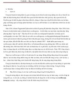
Cursor Measurement Function
The cursor measurement
function allows a high accuracy
measurement of signal values.
When the probes are used, its
attenuation ratio can be
converted automatically. It is
also possible to measure the
voltage value and phase
differences. When the delay
sweep is used, the delay time is also displayed, enabling an
accurate measurement results without any errors due to visual
checks in conventional systems.
Peak to Peak Voltage Measurement
Parameter automatic measurement function enables automatic AC
peak to peak voltage measurement up to 5MHz.
Variable Lock
ON/OFF the vertical and horizontal variable functions can be set
when pressing the ALT/CHOP knob more than 1-second. When
OFF is selected, it becomes CAL level. When the function is ON,
it returns to prior value.
CS-5450
OSCILLOSCOPES
20
3-Channel 8-Trace Waveform Display
CS-5400 series enable the
display of CH3 input in addition
to CH1 and CH2. These three
input signals to CH1, CH2 and
CH3 can be displayed at the
same time as the main (A)
sweep waveform.
Furthermore, an alternated
delay sweep function displayed
as the delayed (B) sweep waveforms of each signal.
High-Sensitivity Design with Vertical Axis of 1 mV/div
The vertical axis sensitivity can be varied continuously from 1
mV/div. to 5 V/div. using the 1-2-5 step attenuator. The 1 mV/div.
position is very useful to measure low-level and complicated
signals. (Frequency response at 1 mV/div. and 2mV/div are DC
to 20 MHz (-3 dB)).
Automaticv Sync (FIX) Function
With this function, the synchronization level is automatically
controlled by tracking the amplitude of the waveform to maintain
the sync lock status. This function eliminates annoying and
complicated synchronization operations.
Easy Operation Panel Layout
The CS-5400 and CS-5450 used touch switches and LEDs. The CS-
5405 and CS-5455 used push switches and lever switches for easy
operation.
Delayed Sweep with Waveform Partial Magnification
Capability
The main (A) sweep waveform
in which the magnified section
is brightened by intensity
modulation and the delayed (B)
sweep waveform which shows
only the magnified section can
be observed simultaneously.
This is a real alternate delayed
sweep.
V Mode Sync for Stable Display of 3 Signals
Even when the CH1, CH2 and
CH3 input signal frequencies
are different, each signal can be
synchronized securely and its
waveform can be displayed
stably.
High-Accuracy ± 2% Design for More Precision Measurement
In order to obtain highly reliable measurement results, the
vertical axis sensitivity and sweep time for the main circuit is
maintained within ± 2% precision. Other specifications also
guarantees the rated values (under temperature conditions of 10
to 35°C, humidity of 85% or less).
CS-5400 SERIES COMMON FEATURES
CS-5405
Wide Dynamic Range and Distortion-Free Accurate Waveform
Display
Its wide dynamic range having greater margins assures the
linearity of the waveforms displayed on the CRT, providing highly
accurate waveform displays without any distortion up to the upper
frequency limits.
21
Maximum Sweep Rate of 5 ns/div (x10 MAG)
The sweep rate can be varied
continually from 0.5 s/div to 50
ns/div. The signal delay line is
installed so that the positive rise
of high-speed signals and high-
frequency signals can be
measured accurately
Built in Video Clamp Circuit for Easy Operation
Built in Video Clamp function which enables observation of the
flame and line TV signals at the touch of a button, while high-
stability synchronization is obtained without performing annoying
synchronizing operations.
Square-Type 150 mm CRT with Self-Illuminated Light and
Inside Scale (12 kV)
A large-sized, square, dome-mesh type CRT with accelerator is
employed. It features both high intensity and high resolution while
providing accurate measurements without parallax view. The auto
focus circuit is also incorporated to display sharp waveforms at all
times.
Single Sweep for Observations of Single-shot Channel
The single sweep function is powerful in measurement of single-
shot or sudden channel. Waveform photography using a camera is
as easy as ordinary, visual observations. It is easy not only for
observations during normal visual inspections but also for camera
shots of the waveforms.
Variable Hold-off Allowing Observation of Waveforms with
Complicated Cycle
Signals which are hard to be synchronized due to complicated
repetition cycles, for example digital signals and video bursts
signal, can be synchronized stably by converting them into the
hold-off time.
High-Accuracy Calibration Signals
A calibration signal output is provided to output the highly
accurate frequency of ± 0.1% and voltage accuracy of ± 1%,
enabling checking of the measurement precision at any required
time.
CH1 Signal Output Connector
The CH1 signal output is obtained by branching the input signal in
the middle of the signal line. As this connector outputs the input
signal at a rate of 50 mV/div, connecting a frequency counter
makes it possible to measure the frequency of a very low signal
while observing its waveform
OSCILLOSCOPES
CS-5400 SERIES
OSCILLOSCOPES
CS-5400 SERIES
● Horizontal TV signal ● Vertical TV signal
OSCILLOSCOPES
22
Other Features
● All position knobs and controls are provided on the front panel.
● A High-sensitivity X-Y function is convenient for the
measurement of phase differences between two input signals.
● A Trace Rotation function allows an easy correction of the
inclination of the trace line due to earth magnetism.
● LINE Synchronization is provided
● A Trace Separation function shifts the B sweep waveform
upward or downward by 4 div. from A sweep waveform.
● The waveform to which the brightness modulation is applied
can also be observed.
● Added or extracted waveforms using ADD and CH2 INV
functions can also be observed.
● Scale illumination convenient for taking photographs or
observation in dark areas is provided.
● CRT scale also provides 0, 10, 90 and 100% indications;
convenient for measurement of rising time, etc.
● A 10-times sweep waveform magnification function (X10 MAG)
is provided.
CS-5455
23
OSCILLOSCOPES
CS-5400 SERIES
OSCILLOSCOPES
CS-5400 SERIES
SPECIFICATIONS
Model CS-5400 CS-5405 CS-5450 CS-5455
CRT Type/accelerating voltage 150 mm rectangular with internal graticule 8 × 10 div. (1 div.=10mm) /approx. 12 kV
Vertical Axis (CH1, CH2)
Sensitivity
5 mV to 5 V/div. ± 2%
1 mV, 2 mV/div. ± 5%
Attenuator 1-2-5 step, 12 ranges, fine adjustable within the selected range
Input Impedance 1 M1 ± 1%, approx. 20 pF
5 mV to 5 V/div
. DC: DC to 100 MHz (within -3 dB) DC: DC to 50 MHz (within -3 dB)
Frequency
AC: 5 Hz to 100 MHz (within -3 dB) AC: 5 Hz to 50 MHz (within -3 dB)
Response
1 mV, 2 mV/div
. DC: DC to 20 MHz (within -3 dB)
AC: 5 Hz to 20 MHz (within -3 dB)
Rising Time
5 mV to 5 V/div. approx. 3.5 ns approx. 7 ns
1 mV, 2 mV/div.: approx. 17.5 ns
Signal Delay Time Leading edge can be confirmed using a square wave that has a rising time of less than this unit
Crosstalk -40 dB (at 1 kHz)
Max. Input Voltage 800 Vp-p or 400 V (DC + AC peak, 1 kHz)
Vertical Axis (CH3)
Sensitivity 0.1 V, 0.5 V/div. ± 2%
Attenuator 0.1 V, 0.5 V/div. 0.1 V/div. 0.1 V, 0.5 V/div.
0.1 V/div.
Input Impedance 1 M1 ± 1%, approx. 20 pF
Frequency Response DC to 100 MHz (within -3 dB) DC to 50 MHz (within -3 dB)
Rising Time Approx. 3.5 ns Approx. 7 ns
Signal Delay Time Leading edge can be confirmed using a square wave that has a rising time of less than this unit
Max. Input Voltage 100 Vp-p or 50 V (DC + AC peak, 1 kHz)
Vertical Axis
Operation Mode CH1, CH2, CH3, ADD, ALT, CHOP
Chopping Frequency Approx. 250 kHz
Polarity Inversion CH2 only
Horizontal (CH2 Input, except × 10 MAG)
Sensitivity
5 mV to 5 V/div. ± 3%
1 mV, 2 mV/div. ± 5%
Input Impedance Same as vertical axis (CH2)
Frequency
DC DC to 1 MHz ( -3 dB)
Response
AC 5 Hz to 1 MHz ( -3 dB)
X-Y Phase Difference Less than 3° at 100 kHz
Operation Mode Switchable to X-Y mode with H.MODE key (CH1: Y axis, CH2: X axis)
Max. Input Voltage Same as vertical axis (CH2)
Sweep
Sweep Mode A, ALT, B, X-Y
Sweep
A Sweep 0.5 s to 50 ns/div. ± 2%, 1-2-5 step, 22 ranges, fine adjustable within the selected range
Time
B Sweep 50 ms to 50 ns/div. ± 2%, 1-2-5 step, 19 ranges
Sweep Magnification × 10 ± 5%, (± 8% at 0.5 µs, 0.1 µs and 50 ns/div. )
Linearity ± 3% (± 5% at × 10 MAG mode)
Hold Off A Sweep, continuously variable from NORM position
Trace Separation B Sweep is continuously variable ± 4 div. with respect to A sweep.
Delay Sweep
AFT.D Continuous delay (After Delay)
Mode
B TRG'D Synchronous delay (B TRIG'D): Synchronized with trigger signal
Delay Time Continuously variable from 0.2 div. to 10 div. (0.5s/div. to 50ns/div.)
Delay Time Error ± (3% of setting value + 1% of full scale) + (0 to 300 ns) : CS-5400, CS-5450
± 4% of reading value : CS-5405, CS5455
Delay Jitter 20000 (10 times of A Sweep setting value) : 1 (at A Sweep 1 ms/div, B Sweep 1 µs/div)
Triggering Mode
Trigger Mode AUTO, NORM, FIX, SINGLE, RESET
Trigger Sources VERT, CH1, CH2, CH3, LINE
Trigger Coupling AC, HF-REJ, DC, TV-F, TV-L
Trigger Sensitivity Coupling Frequency NORM FIX* Frequency NORM FIX*
(NORM MODE)
AC
10Hz to 50MHz 1.0 div 1.5 div 10Hz to 20MHz 1.0 div 1.5 div
50MHz to 100MHz 1.5 div 2.0 div 20MHz to 50MHz 1.5 div 2.0 div
HF-REJ
10Hz to 10kHz 1.0 div 1.5 div 10Hz to 10kHz 1.0 div 1.5 div
10 kHz or more > min > min 10 kHz or more > min > min
DC to 50MHz 1.0 div 1.5 div DC to 20MHz 1.0 div 1.5 div
DC 50MHz to 100MHz 1.5 div 2.0 div 20MHz to 50MHz 1.5 div 2.0 div
TV-F, TV-L Composite video signal 1.5 div Composite video signal 1.5 div
(Above values are obtained with the signal input of: AUTO: 40 Hz or more, FIX: 50 Hz or more
Internal sensitivity indicated as the amplitude on the CRT. Sensitivity in HF-Rej mode ">min" denotes the
amplitude required for synchronization will increase.)
OSCILLOSCOPES
24
Model CS-5400 CS-5405 CS-5450 CS-5455
Calibration Signal
Waveform Square wave
Polarity Positive
Amplitude 1 Vp-p ± 1%
Frequency 1 kHz ± 0.1%
Intensity Modulation
Input Voltage Dims at TTL high level (+5V)
Input Impedance Approx. 10 k1
Frequency Response DC to 5 MHz
Max. Input Voltage 84 Vp-p or 42 V (DC + AC peak, 1 kHz)
CH1 Signal Output (501 Load)
Output Voltage Approx. 50 mVp-p/div.
Output Impedance Approx. 501
Frequency
5 mV to 5 V/div. 100 Hz to 100 MHz (-3 dB) 100 Hz to 50 MHz ( -3 dB)
Response
1 mV, 2 mV/div. 100 Hz to 20 MHz (-3 dB)
Trace Rotation Enables trace rotation adjustment by semi-fixed controller on the panel.
Power Requirements
Input Voltage AC 100/120/220/230 V (±10% )
Frequency 50 Hz / 60 Hz
Power Consumption
Max. 56 W, Max. 45 W, Max. 55 W, Max. 44 W,
Max. 69 VA Max. 58 VAA Max. 68 VA Max. 57 VA
Insulator Voltage AC 1.5 kV, 1 minute
Insulator Resistance More than 100M1 at DC 500 V
Dimensions/Weight
Dimensions (W × H × D) 305 × 150 × 400 mm /(344 × 165 × 459 mm, Maximum dimensions)
Weight Approx. 9.3 kg Approx. 8.8 kg Approx. 9.3 kg Approx. 8.8 kg
Operating Environment (limited as indoor use)
Altitude Below 2000 m
Overvoltage Category II
Pollution 2
Operating Temperature & Humidity 0 to +40°C, 85% or less (with no condensation)
Storage Temperature & Humidity -20 to +70°C, 85% or less (with no condensation)
Accessories
Probe
PC-51 (2) PC-59 (2) PC-53 (2) PC-54 (2)
Operation Manual (1)/Adjusting Screwdriver (1)/Power Cable (1)/Replacement (1)
25
OSCILLOSCOPES
CS-5400 SERIES
OSCILLOSCOPES
CS-5400 SERIES
Readout Section (CS-5400, CS-5450 only)
Panel Setup Value CH1, CH2 scale factor (with probe detection), CH3 scale factor, V-UNCAL, ADD, INV,
A/B Sweep scale factor (MAG conversion, "" is displayed in MAG mode), X-Y, Sweep UNCAL, DELAY, TIME, B TRIG'D
Cursor Measurement 6V1: Voltage display by converting CH1 scale factor
6V1 only in X-Y mode 6V2: Voltage display by converting CH2 scale factor
(Measures between 6REF and 6V3: Voltage display by converting CH3 (0.1V/div. or 0.5V/div.) scale factor
cursor except the parameter 6T : Time display by converting A Sweep scale factor
automatic measurement) 61/T: Frequency display by converting Sweep scale factor
DCV, Vp-p, FRQ, PER Display the parameter measurement value by automatic measurement function
VARIABLE or
RATIO: Voltage ratio, time ratio display with 5 div. on the CRT as 100%
PHASE: Phase difference display with 5 div. on the CRT as 360°
A VARIABLE at UNCAL
DCV >, Vp-p >: Display ">" and inform that the input signal is larger than measurement value on CRT
Resolution/Measurement Error 10 bits/± 4%
Measuring Range
Vertical: More than ± 3.6 div. from the center of CRT
Horizontal: More than ± 4.6 div. from the center of CRT
Parameter auto setting function Each parameter is measured and displayed for the signal selected as the trigger signal source from CH1 or CH2
Frequency (FRQ) Mode selectable in Cursor mode. Measured with internal counter to be displayed
Frequency Range CS-5400: 2 Hz to 100 MHz CS-5450: 2 Hz to 50 MHz
Effective Digits/Accuracy 5 digits/0.01% ± 1 digit
Measurement Sensitivity Same as trigger sensitivity
Period (PER) Mode selectable in Cursor mode. Measured with internal counter to be displayed
Measurement Range CS-5400: 0.5 s to 10 ns CS-5450: 0.5 s to 20 ns
Effective Digits/Accuracy 5 digits/0.01% ±1 digit
Measurement Sensitivity Same as trigger sensitivity
AC Voltage (Vp-p) Mode selectable in Cursor mode. Peak-to-peak voltage is measured and displayed
Measurement Range 10 Hz to 1MHz: 0.5 div. to Effective CRT area 1MHz to 5MHz: 2.0 div. to Effective CRT area
Frequency Range 10 Hz to 5 MHz
Effective Digits 3 digits
10 Hz to 40 Hz: ± {8% + attenuator setup value (V/div) × 0.04 div}
Accuracy 40 Hz to 1 MHz: ± {3% + attenuator setup value (V/div) × 0.04 div}
1 MHz to 5 MHz: ± {5% + attenuator setup value (V/div) × 0.04 div}
DC Voltage (DCV) Mode selectable in Cursor more. Average DC voltage is measured and displayed
Sensitivity 0.5 div. to Effective CRT area
Effective Digits 3 digits
Accuracy ± {3% + attenuator setup value (V/div) × 0.04 div}
Auto Setup For CH1, CH2, Vertical axis attenuator, Sweep range, Vertical position, Horizontal position are automatically setup
Period 1.5 to 5 periods (H.Variable,: CAL mode, for input signal up to 10 MHz)
Amplitude Within effective CRT area (within 1/2 of effective CRT area in dual-trace mode)
Frequency (Sine wave) CS-5400: 50 Hz to 100 MHz, CS- 5450: 50 Hz to 50 MHz
Position
Vertical axis: 1 channel ; almost center of CRT, 2 channel ; CH1 approx. +2 div., CH2 approx. -2 div. from the
center of CRT
Horizontal axis: starts from left edge of CRT scale
Backup
Panel setup values are backed up by built-in battery. Battery service life approx. 30,000 hours (with room
temperature)