Handbook of petroleum processing CCR
Bạn đang xem bản rút gọn của tài liệu. Xem và tải ngay bản đầy đủ của tài liệu tại đây (263.23 KB, 21 trang )
Chapter 5
Catalytic reforming
Peter R. Pujad´o and Mark Moser*
Catalytic reforming is a process whereby light petroleum distillates (naphthas) are
contacted with a platinum-containing catalyst at elevated temperatures and hydrogen
pressures ranging from 345 to 3,450 kPa (50–500 psig) for the purpose of raising the
octane number of the hydrocarbon feed stream. The low octane, paraffin-rich naphtha
feed is converted to a high-octane liquid product that is rich in aromatic compounds.
Hydrogen and other light hydrocarbons are also produced as reaction by-products. In
addition to the use of reformate as a blending component of motor fuels, it is also a
primary source of aromatics used in the petrochemical industry (1).
The need to upgrade naphthas was recognized early in the 20th century. Thermal pro-
cesses were used first but catalytic processes introduced in the 1940s offered better
yields and higher octanes. The first catalysts were based on supported molybdenum
oxide, but were soon replaced by platinum catalysts. The first platinum-based reform-
ing process, UOP’s Platforming™ process, came on-stream in 1949. Since the first
Platforming unit was commercialized, innovations and advances have been made con-
tinuously, including parameter optimization, catalyst formulation, equipment design,
and maximization of reformate and hydrogen yields. The need to increase yields and
octane led to lower pressure, higher severity operations. This also resulted in increased
catalyst coking and faster deactivation rates.
The first catalytic reforming units were designed as semiregenerative (SR), or fixed-
bed units, using Pt/alumina catalysts. Semiregenerative reforming units are peri-
odically shut down for catalyst regeneration. This involves burning off coke and
reconditioning the catalyst’s active metals. To minimize catalyst deactivation, these
units were operatedathigh pressures in the range of 2,760 to3,450 kPa (400–500 psig).
High hydrogen pressure decreases coking and deactivation rates.
*
c
UOP LLC
217
218 CHAPTER 5
Catalytic reforming processes were improved by introducing bimetallic catalysts.
These catalysts allowed lower pressure, higher severity operation: ∼1,380–2,070 kPa
(200–300 psig), at 95–98 octane with typical cycle lengths of one year.
Cyclic reforming was developed to allow operation at increased severity. Cyclic re-
forming still employs fixed-bed reforming, but each reactor in a series of reactors
can be removed from the process flow, regenerated, and put back into service without
shutting down the unit and losing production. With cyclic reforming, reactor pressures
are approximately 200 psig, producing reformates with octanes near 100.
Another solution to the catalyst deactivation problem was the commercialization of the
Platforming process with continuous catalyst regeneration, or the CCR Platforming
process, by UOP in 1971. The Institut Fran¸cais du P´etrole announced the commer-
cialization of a similar continuous regeneration reforming process a few years later.
With CCR small amounts of catalyst are continuously removed from the last reac-
tor, regenerated in a controlled environment, and transferred back to the first reactor.
The CCR Platforming process has enabled the use of ultra low pressures at 345 kPa
(50 psig) with product octane levels as high as 108. More than 95% of all new cat-
alytic reformers are designed with continuous regeneration. In addition, many units
that were originally built as SR reforming units have been revamped to continuously
regenerable reforming units.
Figure 5.1 illustrates the evolution of catalytic reforming, in terms of both process
yields and octane numbers.
Increase in Catalytic Reforming
Performance with Catalyst and Process Innovation
RON Clear
86 90 94 98 102 106
Theoretical Yield
90
C5 Yield, LV%
86
82
78
1950s
1960s
1970s
1980s
1990s
Figure 5.1. Increased yields and octane with Platforming advances (reprinted with permission from UOP
LLC).
CATALYTIC REFORMING 219
150
200
250
300
350
400
IBP 10 30 50 70 90 EP
Percent Over
Temperature, °F
Figure 5.2. ASTM D-86 distillation curve for naphtha (1).
Feedstocks
Naphtha feedstocks to reformers typically contain paraffins, naphthenes, and aromat-
ics with 6–12 carbon atoms. Most feed naphthas have to be hydrotreated to remove
metals, olefins, sulfur, and nitrogen, prior to being fed to a reforming unit. A typical
straight run naphtha from crude distillation may have a boiling range of 150–400
◦
F
(65–200
◦
C).
In addition to naphthas from crude distillation, naphthas can be derived from a variety
of other processes that crack heavier hydrocarbons to hydrocarbons in the naphtha
range. Cracked feedstocks may be derived from catalytic cracking, hydrocracking,
cokers, thermal cracking, as well as visbreaking, fluid catalytic cracking, and synthetic
naphthas obtained, for example, from a Fischer–Tropsch process.
Light paraffinic naphthas are more difficult to reform than heavier naphthenic hydro-
carbons. Distillation values for the initial boiling point, the mid-point at which 50%
of the naphtha is distilled over, and the end point are often used to characterize a
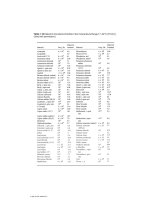
naphtha (Figure 5.2). If available, however, it is best to have a detailed component
breakdown as provided by gas chromatographic analysis (Table 5.1).
Feed hydrotreating is used to reduce feedstock contaminants to acceptable levels
(Figure 5.3). Common poisons for reforming catalysts that are found in naphtha
are sulfur, nitrogen, and oxygen compounds (Figure 5.4). Removing these requires
breaking of a carbon-sulfur, -nitrogen or -oxygen bond and formation of hydrogen
sulfide, ammonia, or water, respectively. Hydrotreaters will also remove olefins and
metal contaminants.
Some hydrotreaters are two-stage units. The first stage operates at low temperature
for the hydrogenation of diolefins and acetylenes that could polymerize and plug the
second, higher severity stage. The effluent from the first stage is cooled and fed to
220 CHAPTER 5
Table 5.1. Composition of a typical naphtha
Concentration (wt%)
Aromatics
Benzene 1.45
Toluene 4.06
Ethylbenzene 0.52
p-Xylene 0.92
m-Xylene 2.75
o-Xylene 0.87
C9+ Aromatics 3.31
Total Aromatics 13.88
Total Olefins 0.11
Paraffins and Naphthenes
Propane 0.79
Isobutane 1.28
n-Butane 3.43
Isopentane 5.62
n-Pentane 6.19
Cyclopentane 0.64
C6 Isoparaffins 6
n-Hexane 5.3
Methylcyclopentane 2.58
Cyclohexane 3.26
C7 Isoparaffins 4.55
n-Heptane 4.65
C7 Cyclopentanes 2.77
Methylcyclohexane 7.57
C8 Isoparaffins 4.24
n-Octane 3.43
C8 Cyclopentanes 1.52
C8 Cyclohexanes 5.23
C9 Naphthenes 3.63
C9 Paraffins 5.93
C10 Naphthenes 1.66
C10 Paraffins 3.41
C11 Naphthenes 1.04
C11 Paraffins 0.53
C12 P + N 0
> 200 P + N 0
Total Paraffins 55.35
Total Naphthenes 30.7
CATALYTIC REFORMING 221
Heater
Reactor
Separator
Stripper
Fresh
Feed
Recycle Gas
Compressor
Light Ends
Stea
Desulfurized
Product
Hydrogen
Makeup
Makeup
Compressor
Sour
Water
Wash
Water
Steam
Figure 5.3. Naphtha hydrotreater flow scheme.
the second stage for the hydrogenation of olefins and the removal of sulfur and nitrogen
compounds.
The reformate stream from acatalytic reforming unit isinvariably used either as a high-
octane gasoline blending component or as a source of aromatics—BTX (benzene,
toluene, and xylenes), and C
9
+ aromatics. Reforming for motor fuel applications
still represents the majority of existing reforming capacity. Reformate specifications
(octane, vapor pressure, end point, etc.) are set to provide an optimum blending prod-
uct. The octane requirement is met through the production of high-octane aromatics,
the isomerization of paraffins, and the removal of low octane components by cracking
them to gaseous products. Feedstocks to these units are typically “full range” naph-
thas, consisting of hydrocarbons with 6–12 carbon atoms; however, the initial boiling
point may be varied to limit the presence of benzene precursors.
Reforming units for the production of aromatics are often called BTX reformers.
Naphthas for these units are specified to contain mostly naphthenes and paraffins of
6–8 carbons. The desired reaction is aromatization through dehydrogenation of the
naphthenes, and cyclization and dehydrogenation of the paraffins to the analogous
aromatic.
Mercaptans Di–sulfides Thiophene
R SH R S R
C
S
C C
C
Figure 5.4. Sulfur types.
222 CHAPTER 5
Table 5.2. Reformate composition
mass% liq-vol%
Aromatics
Benzene 3.72 3.39
Toluene 13.97 12.93
Ethylbenzene 3.13 2.90
p-Xylene 3.39 3.14
m-Xylene 7.47 6.91
o-Xylene 4.83 4.47
C9+ Aromatics 36.05 33.30
Total aromatics 72.56 67.04
Total olefins 0.82 1.02
Paraffins and naphthenes
Propane 0.00 0.00
Isobutane 0.14 0.20
n-Butane 0.94 1.32
Isopentane 2.52 3.29
n-Pentane 1.74 2.29
Cyclopentane 0.10 0.10
C6 Isoparaffins 3.91 4.77
n-Hexane 1.74 2.12
Methylcyclopentane 0.28 0.30
Cyclohexane 0.03 0.03
C7 Isoparaffins 7.70 9.02
n-Heptane 2.22 2.60
C7 Cyclopentanes 0.33 0.35
Methylcyclohexane 0.04 0.04
C8 Isoparaffins 2.86 3.24
n-Octane 0.62 0.70
C8 Cyclopentanes 0.14 0.14
C8 Cyclohexanes 0.06 0.06
C9 Naphthenes 0.04 0.04
C9 Paraffins 0.90 0.99
C10 Naphthenes 0.04 0.04
C10 Paraffins 0.24 0.26
C11 Naphthenes 0.00 0.00
C11 Paraffins 0.03 0.04
C12 P + N 0.00 0.00
Poly Naphthenes 0.00 0.00
> 200 P + N 0.00 0.00
Total Paraffins 25.56 30.84
Total Naphthenes 1.06 1.10
CATALYTIC REFORMING 223
Reformate properties
Table 5.2 shows a typical reformate composition. For motor fuel applications, the
octane number is the dominant parameter of product quality. A higher octane number
reflects a lower tendency of the hydrocarbon to undergo a rapid, inefficient detonation
in an internal combustion engine. This rapid detonation is heard as a knocking sound in
the engine, so octane is often referred to as the antiknock quality of a gasoline. Motor
fuel octanes are measured at low engine speeds (research octane number or RON) or
at high engine speeds (motor octane number or MON). In the United States, the octane
values posted on gasoline pumps are the arithmetic average of the MON and the RON.
The acronym RONC, research octane number clear, is used to denote that there are no
additives, such as lead, used to increase octane number. Table 5.3 provides a listing
of the various octanes of pure hydrocarbons according to the American Petroleum
Institute, API (2).
Octane numbers of a hydrocarbon or hydrocarbon mixture are determined by com-
paring its antiknock qualities with various blends of n-heptane (zero octane) and
2,2,4-trimethylpentane, or iso-octane (100 octane). Hydrocarbons may appear to
have different octane numbers when blended with other hydrocarbons of a differ-
ent composition—these are denoted as “blending octanes” and may be significantly
different from the actual octane numbers of the individual hydrocarbon components
(Table 5.4) (3).
Other property specifications of the reformate include volatility or vapor pressure,
often given in terms of the Reid vapor pressure or RVP, end point, color, etc. (3) High-
end point reformates, for example, may not combust well in an internal combustion
engine.
Table 5.3. Examples of research and motor
octanes of pure hydrocarbons
RON MON
Paraffins
n-heptane 0 0
2-methylhexane 42.4 46.3
3-ethylpentane 65.0 69.3
2,4-dimethylpentane 83.1 83.8
Aromatics
Toluene 120.1 103.2
Ethylbenzene 107.4 97.9
Isopropylbenzene 113.0 99.3
1-methyl-3-ethylbenzene 112.1 100.0
1,3,5-trimethylbenzene >120 >120
224 CHAPTER 5
Table 5.4. Octane and blending octane numbers by
research method
RON Blending Octane
2,2-dimethyl butane 92.8 89
2-methyl-1-butene 102 146
Cyclopentane 101 141
1,4-dimethylbenzene 117 146
Reformulated gasolines, a requirement of the 1990 Clean Air Act, are the subject
of much legislation. Specifications require a lower benzene content, lower volatility,
and lower end point. Other specifications may pertain to the oxygenate content and
other factors that affect the burning characteristics. The gasolines available to the
consumer consist of a mixture of gasoline fractions from many refinery sources,
including: straight run (unprocessed fraction), isomerate, alkylate, reformate, and
FCC fractions, and, on occasion, polymer gasolines.
Reforming reactions
In BTX production, the objective is to transform paraffins and naphthenes into ben-
zene, toluene, and xylenes with minimal cracking to light gases. The yield of desired
product is the percentage of feed converted to these aromatics. In motor fuel ap-
plications, octane values of the feed may be raised via aromatization or through
isomerization of the paraffins into higher octane branched species without sacrificing
yield. Yield is typically defined as liquid product with five or more carbons.
Typical catalysts that consist of platinum supported on alumina (with or without other
metals or modifiers) are bifunctional in that separate and distinct reactions occur on the
platinum site and on the alumina. The platinum typically performs dehydrogenation
and hydrogenolysis, while the acidic alumina isomerizes, cyclizes, and cracks.
The dehydrogenation of naphthenes to aromatics is probably the most important
reaction. Feeds contain cyclopentanes and substituted cyclopentanes, as well as cy-
clohexanes and their homologues. Six carbon ring cyclohexanes, for example, can be
directly dehydrogenated to produce aromatics and hydrogen.
+
3H
2
Dehydrogenation is typically catalyzed by the platinum function on the reforming
catalyst.
CATALYTIC REFORMING 225
Five member ring cyclopentanes must be hydroisomerized to give a cyclohexane
intermediate prior to dehydrogenation to aromatics.
+ 3H
2
Acid-catalyzed reactions together with the Pt-catalyzed dehydrogenation function are
largely responsible for hydro-isomerization reactions that lead to the formation of
aromatics.
Paraffin conversion is the most difficult step in reforming. For that reason, the ability
to convert paraffins selectively is of paramount importance in reforming. Paraffins
may be isomerized over the acidic function of the catalyst to provide higher octane
branched paraffins.
CH
3
CH
3
CH
3
CH
3
CH
3
CH
3
Another acid catalyzed paraffin reaction is cracking to lighter products, thus remov-
ing them from the liquid product. Octane is improved through the removal of low
octane paraffinic species from the liquid product by their conversion to gaseous,
lower molecular weight paraffins.
H
3
C CH
3
+ H
2
H
3
C
CH
3
+
H
3
C CH
3
Paraffins also undergo cyclization to cyclohexanes. This reaction is believed to pro-
ceed through an olefin intermediate, produced by Pt-catalyzed dehydrogenation (4).
The cyclization of the olefin may be catalyzed by the alumina support.
+ H
2
+
H
2
CH
3
CH
3
CH
3
H
3
C
226 CHAPTER 5
After cyclization, cyclohexane undergoes dehydrogenation to aromatics. Cyclopen-
tanes undergo hydroisomerization to cyclohexane, followed by dehydrogenation to
aromatics. Aromatics are stable species and relatively inert. Reactions of substi-
tuted aromatics involve isomerization, hydrodealkylation, disproportionation, and
transalkylation.
Small amounts of olefins are formed that also undergo a number of isomerization,
alkylation, and cracking reactions. In particular, they appear to play an important role
as an intermediate in cyclization reactions.
The dehydrogenation of naphthenes and paraffins is rapid and equilibrium concentra-
tions are established in the initial portions of a catalyst bed. Isomerization reactions
are sufficiently fast that actual concentrations are near equilibrium. The observed re-
action rate for dehydrocyclization is reduced by the low concentrations of the olefin
intermediates that exist at equilibrium. Hydrogen partial pressure significantly affects
olefin equilibrium concentrations and has a significant impact on aromatization and
dehydrocyclization of paraffins. Lowering hydrogen partial pressures results in an
increase in the rate of aromatization, a decrease in the rate of hydrocracking, and an
increase in the rate of coke formation.
Table 5.5 provides thermodynamic data for typical compounds in reforming reactions
at a reference temperature of 800
◦
K. Thermodynamic data can be obtained from
Table 5.5. Thermodynamic data for reforming compounds at 800
◦
K,
ideal gas in kcal/mol
Reforming reactions are typically dehydrogenations of the form
A ↔ B + nH
2
with equilibrium expressed in the form
K
P
=
p
B
(p
H
2
)
n
p
A
such that they are a strong function of the partial pressure of hydrogen.
H
o
f
G
o
f
Typical C
6
’s
n-hexane −48.26 73.08
2-methylpentane −49.68 72.74
3-methylpentane −49.32 73.67
Cyclohexane −37.19 75.94
Methyl cyclopentane −33.73 71.92
Benzene 15.51 52.84
Typical C
7
’s
n-heptane −54.20 87.43
2-methylhexane −55.91 87.23
3-methylhexane −55.28 87.07
Methyl cyclohexane −45.10 86.15
Toluene 6.65 61.98
CATALYTIC REFORMING 227
standard sources (e.g., 2 and 5). Production of aromatics is favored by the reforming
conditions. Current designs at low hydrogen partial pressures ensure full conversion
to the equilibrium limits.
Catalysts
The platinum must be dispersed over the alumina surface such that the maximum
number of active sites for dehydrogenation is available. Platinum cluster size dimen-
sions are on the order of angstroms, or 10
−10
meters. The interaction of the platinum
with the alumina surface is such that the platinum clusters are relatively immobile and
do not agglomerate during reforming. Sulfidation of the platinum is sometimes used
to partially poison the platinum, or reduce its activity; this has the beneficial effect
of reducing a major portion of the hydrogenolysis, or metal-catalyzed cracking reac-
tions. Liquid product yields are improved and the light gas production, particularly
methane, is reduced.
The alumina support is usually in the eta (η) or gamma (γ ) phase, but most often
gamma is used in reforming. Chloride is added to promote acidity. A simplified
schematic diagram of the alumina functionality is given in Figure 5.5.
Catalysts that are used in reactors where the catalyst bed is not easily removed after
deactivation must have long catalyst life cycles. A typical fixed bed catalyst life cycle
may be a year or longer. Modifiers are added to reduce the effect of coke buildup and to
lengthen the catalyst cycle length, either by hydrogenating the coke to a less graphitic
species (6) or by cracking the coke precursors (7). Elements that are commonly added
to the catalysts are rhenium and, to a lesser extent, iridium.
In moving bed units (8) the catalyst flows through the reactors and is regenerated
continually in a sepaarte regeneration vessel that is part of the reactor–regenerator
loop. Process conditions are much more severe, thus shortening catalyst life and
requiring regeneration cycles of only a few days. In moving bed catalysts elements
are added, such as tin and germanium, to increase liquid, aromatic, and hydrogen
yields by reducing the activity of the platinum for hydrogenolysis or metal-catalyzed
cracking reactions. These components also provide some stabilization of the catalyst
relative to Pt alone.
H
O
O
O
Cl
Al Al
Al
Figure 5.5. Alumina schematic.
228 CHAPTER 5
Deactivation mechanisms for reforming catalysts include coking, poisoning, and ag-
glomeration of the platinum. Under normal conditions coke accumulates on the cata-
lyst. In a fixed bed or SR unit, this coke will deactivate the catalyst such that, in time,
the temperature limit of the reforming unit will be reached, or the selectivity to desired
products is too much reduced, or the octane of the liquid product is declining. When
this occurs, the refiner will shut down the process unit and regenerate the catalyst to re-
turn it to itsoriginal state. In a moving bed unit, some ofthe catalyst is continually being
regenerated outside the process and returned to the reactors. High selectivity and ac-
tivity are maintained. New, degradation-resistant catalysts allow the refiner to operate
continuous regeneration units for more than eight years before removing the catalyst.
The actual chemistry and steps for regeneration for all process units are very similar.
In the following discussion, catalyst regeneration for a SR reformer is described. For
cyclic or continuous reformers, plant shutdown and start-up are unnecessary and the
remaining steps are accomplished in equipment outside the process stream.
The objective of regeneration is to return the catalyst to its initial, fresh state. If
the regeneration is successful, there is no difference between fresh and regenerated
catalyst. To do this, the coke must be burnt off the catalyst, the platinum should be well
dispersed and in a reduced state, and the acidity should be properly adjusted through
chloride adsorption. These needs account for the steps in regeneration; carbon burn,
chloride redispersion and metals reduction.
In order to conduct a regeneration, the heater temperatures and feed rates are reduced
gradually. The circulation of recycle gas is continued to strip hydrocarbons from the
catalyst, leaving only coke. If the coke is to be burnt in the unit, higher temperatures
are maintained and the coke burning procedure is initiated. If the coked catalyst is
to be removed from the unit, temperatures are lowered, to about 100–150
◦
F before
unloading. Since coked catalyst is often pyrophoric, nitrogen blanketing is often used
to protect the catalyst from air contact and combustion.
The coke burning step must be carefully monitored. The combustion of coke to car-
bon dioxide and water is exothermic, and the oxygen concentration must be kept low
to limit the reaction and temperature rise. Excessive temperature can cause agglom-
eration of the platinum or, in more extreme cases, can cause the alumina to change
CATALYTIC REFORMING 229
from the desired phase or crystal structure to a higher temperature phase. The water
produced in the combustion also facilitates sintering of platinum. Due to the need to
gradually burn coke, the carbon burn is usually the most time-consuming part of a
regeneration.
Coke burning is usually done in the range of 400–500
◦
C, and at oxygen concentrations
initially in the 1–2 mol% range. Oxygen content and temperature are often increased
during burning to ensure that all coke has been combusted by the end of the burn.
Oxygen consumption is monitored to determine the total amount of coke combusted
and the extent of the burn.
Since platinum can agglomerate even at relatively moderate exothermic conditions,
the platinum must be redispersed after the carbon burn. The temperature is first
increased to approximately 500
◦
C, oxygen content to approximately 5–6 mol%, and
chlorine or an organic chloride that breaks down to HCl and Cl
2
is injected into the
air/nitrogen stream. Platinum oxychlorides or chlorides form that redisperse platinum
over the alumina surface, ensuring that almost all the platinum is exposed for reaction.
This also adds chloride to the catalyst to enhance its acidity.
Finally, the last step in the regeneration process is the reduction of the metals on the
catalyst and sulfiding, if necessary. This is done in a dry hydrogen atmosphere. At
the temperatures required for reduction, greater than 350
◦
C, high moisture levels can
lead to platinum agglomeration. Since water is formed in the reduction process as
platinum oxide is reduced to platinum metal, water is drained from the unit during
reduction. The reduction hydrogen is recirculated at as high a rate as possible in order
to minimize moisture content.
Sulfiding is typically done by injection of H
2
S or of an organic sulfide into the unit at
the end of reduction. Sulfiding is continued until the specified sulfur level is reached
or until sulfur is no longer adsorbed by the catalyst and is detected at the outlet of the
catalyst bed.
Reactor performance
The major process variables that affect unit performance are reactor pressure, reactor
temperature, space velocity, H
2
/HC molar ratio, and catalyst type. The relationship
between the variables and process performance is generally applicable to both SR and
continuous regeneration modes of operation.
The reactor pressure declines across the various reaction stages. The change in reactor
pressure across the unit, known as pressure drop, can be quite high for high-pressure
reforming units, often 50–60 psig or more. The average reactor operating pressure is
generally referred to as reactor pressure. For practical purposes, a close approximation
230 CHAPTER 5
is the last reactor inlet pressure. The reactor pressure affects reformer yields, reactor
temperature requirements, and catalyst stability.
Practical operating constraints have led to a historical range of operating pressures
from 345 to 4,830 kPa (50–700 psig). Decreasing the reactor pressure increases
hydrogen and reformate yields, decreases the required temperature to achieve product
quality, and shortensthe catalyst cycle because itincreases the catalyst coking rate. The
high catalyst deactivation rate associated with lower operating pressure requires CCR.
The primary control for product quality in catalytic reforming is the temperature of
the catalyst beds. Platforming catalysts are capable of operating over a wide range of
temperatures. By adjusting the heater outlet temperatures, a refiner can change the
octane of the reformate and the quantity of the aromatics produced.
The reactor temperature can be expressed as the weighted average inlet temperature
(WAIT). The WAIT is the summation of the product of the fraction of catalyst in
each reactor multiplied by the inlet temperature of the reactor. The weighted average
bed temperature (WABT) is also used to describe catalyst temperature and is the
temperature of the catalyst integrated along the catalyst bed. Temperatures in this
chapter refer to the WAIT calculation. Typically, SR Platforming units have a WAIT
range of 490–525
◦
C (914–977
◦
F). CCR Platforming units operate at a WAIT of 525–
540
◦
C (977–1,004
◦
F). CCR Platforming units operate at even higher temperatures to
produce a more aromatic-rich, high-octane product. The amount of naphtha processed
over a given amount of catalyst over a set length of time is referred to as space velocity.
Space velocity corresponds to the reciprocal of the residence time or time of contact
between reactants and catalyst. When the hourly volume charge rate of liquid naphtha
is divided by the volume of catalyst in the reactors, the resulting quotient, expressed in
units of h
−1
, is the liquid hourly space velocity (LHSV). Typical commercial LHSV
range from 1 to 3 with the volumetric rates measured at standard conditions (60
◦
F
and 1 atm.abs.).
Alternatively, if the weight charge rate of naphtha is divided by the weight of catalyst,
the resulting quotient, also expressed in units of h
−1
, is the weight hourly space
velocity (WHSV). Whether LHSV or WHSV is used is based on the customary way
that feed rates are expressed at a given location. Where charge rates are normally
expressed in barrels per stream day, LHSV is typically used. Where the rates are
expressed in terms of metric tons per day, WHSV is preferred.
The combination of space velocity and reactor temperature is used to set the octane
of the product. The greater the space velocity, the higher the temperature required to
produce a given product octane. If refiners wish to increase the severity of a reformer
operation, they can either increase reactor temperature or lower the space velocity by
decreasing the reactor charge rate.
CATALYTIC REFORMING 231
The hydrogen-to-hydrocarbon (H
2
/HC) mol ratio is the ratio of mols of hydrogen in
the recycle gas to mols of naphtha charged to the unit. The recycle gas is a mixture of
hydrogen and light gases, typically 75–92 mol% hydrogen. The ratio of total recycle
gas to hydrocarbon is sometimes called the gas-to-oil ratio. Recycle hydrogen is
necessary to maintain catalyst-life stability by sweeping coke precursors from the
catalyst metals. The exact mechanism is proposed to be hydrogenation and inhibition
of polymerization. The rate of coke formation on the catalyst is a function of the
hydrogen partial pressure present. Increasing the H
2
/HC ratio increases the hydrogen
partial pressure and removes coke precursors from the metal sites, thereby increasing
stability with little effect on product quality or yields.
Except for units designed for continuous regeneration through the circulation of the
catalyst between the reactors and the regenerator, catalytic reforming units normally
will require a shutdown for regeneration every 6–12 months. This relatively long
cycle can be obtained by operating under milder conditions of high partial pressure of
hydrogen, lower reactor temperatures, and lower octane products. Continuous units
operate under severe conditions to yield high octane, high aromatics production, at
low hydrogen partial pressures, and higher reactor temperatures. Different catalysts
are used depending on the application.
Semi regenerative reformers make use of catalysts the contain platinum or plat-
inum modified by rhenium or, to a lesser extent, iridium. The support is most of-
ten gamma alumina, although there have been uses of eta alumina (4). Rhenium
or iridium is used to enhance the life of the catalyst over that observed for Pt-only
catalysts. All these catalysts are typically sulfided to minimize metal-catalyzed hy-
drogenolysis reactions that produce light gases and reduce gasoline yield. Additional
components were used on catalysts commercialized in the 1990’s. The use of two
catalysts in a SR unit; one catalyst in the front reactors and another catalyst in the
back reactors to provide maximum yield, activity, and stability was commercialized in
1994 (8).
There are two main shapes of catalysts, cylindrical and spherical. The cylindrical
catalysts are usually extruded alumina. The spherical catalysts may be formed through
a dropping method or by rolling wet, soft alumina dough. In some instances, factors
such as the resistance to flow or flow distribution concerns may cause one form to
be chosen over the other. The density of the catalysts may vary from approximately
0.5–0.8 g/cm
3
. The variability in density allows the refiner to load more pounds of
catalyst in a unit, should additional catalyst activity or stability be desired.
The process of moving catalyst from the reactors to the regenerator and back re-
quires the use of spherical catalysts, rather than extrudate, to avoid catalyst dusting
and breakage. Continuous regeneration units are operated at high severity and low
pressures to produce the greatest amount of aromatics and hydrogen possible. The
232 CHAPTER 5
catalyst is circulated at a rate such that it corresponds to about one regeneration per
week or even at a greater frequency if needed due to the rapid deactivation under these
conditions.
Typical catalysts used in these units had a composition of platinum and tin on gamma
alumina. The tin was used to reduce the hydrogenolysis activity of the platinum and
to improve yields. The reduction in metal-catalyzed cracking is also considered to
stabilize the catalyst relative to platinum only. Currently, new proprietary catalysts
are used to increase yields, lower coke make, or allow higher throughput (9).
Process flow schemes
Fixed bed semiregenerative reforming
A typical SR Platforming flow diagram is presented in Figure 5.6. Feed to the unit
is mixed with recycled hydrogen gas, raised to the reaction temperature first by a
feed-effluent combined feed exchanger and then by a fired heater, and then charged to
Figure 5.6. Semiregenerative reforming process (reprinted with permission from UOP LLC).
CATALYTIC REFORMING 233
the reactor section. Because most of the reactions that occur in the Platforming process
are endothermic, the reactor section is separated into several stages, or reactors.
Interheaters are installed between these stages to maintain the desired temperature
range across the catalyst in the reactor section. Effluent from the last reactor is cooled
by the feed-effluent heat exchanger for maximum heat recovery. Air or water cooling
provides additional cooling to near-ambient temperature. The effluent is then charged
to the separation section, where the liquid and gas products are separated. A portion of
the gas from the separator is compressed and recycled back to the reactor section. The
net hydrogen produced is sent to hydrogen users in the refinery complex or for use as
fuel. The separator liquid is pumped to a product stabilizer, where the more-volatile
light hydrocarbons are fractionated from the high-octane liquid product.
Fixed bed cyclic reforming
Cyclic reforming is similar to SR reforming, but an additional reactor replaces one
of the primary reactors while that reactor is being regenerated. The frequency with
which a particular primary reactor is replaced and regenerated depends upon its rate
of deactivation. Large diameter valves and piping are used to vary the process flow
between reactors.
Platforming process with continuous catalyst regeneration
In parallel with bimetallic catalyst improvements and other process and regeneration
advances, UOP began to develop the CCR Platforming™ process (Figure 5.7). In the
CCR Platforming unit, partially aged catalyst in the reactors is continuously replaced
with catalyst that has been freshlyregenerated in an external regenerator(CCR section)
to maintain a low average age for the reactor catalyst. Thus, the high selectivity
and high activity characteristics associated with new catalyst can be maintained at
significantly higher severities than with the SR Platforming process. For example, a
SR Platforming unit operates at a severity that steadily builds coke up on the catalyst
surface over the length of a cycle (6–18 months), at which point the unit is shut
down and the catalyst regenerated. Throughout the cycle, yields decline. Instead, in a
modern CCR Platforming unit, the catalyst is regenerated approximately every three
to seven days and the yield does not decline.
The ability tocontinuously regenerate a controlled quantity of catalyst is the significant
innovation of the CCR Platforming unit. The catalyst flows by gravity from the last
reactor into a catalyst collector vessel. The catalyst is lifted by either nitrogen or
hydrogen lifting gas to a catalyst hopper above the regeneration tower. Catalyst then
flows to the regeneration tower, where the catalyst is reconditioned. Regenerated
catalyst is returned to the top of the reactor stack by a transfer system similar to
that used in the reactor-to-regenerator transfer. Thus, the reactors are continuously
supplied with freshly regenerated catalyst, and product yields are maintained at fresh
234 CHAPTER 5
Figure 5.7. CCR Platforming process (reprinted with permission from UOP LLC).
catalyst levels. The regeneration and reactor sections of the unit are easily isolated to
permit a shutdown of the regeneration system for normal inspection or maintenance
without interrupting of the Platforming operation.
A few years after the introduction of the UOP CCR Platforming process, another con-
tinuously regenerable process design was offered by the Institut Fran¸cais du P´etrole.
Though similar to CCR Platforming, the continuous reforming units designed by the
Institut Fran¸cais du P´etrole differ most notably in that the reactors are located side-
by-side and the catalyst transfer is effected through transfer piping between reactors.
Advantages of CCR Platforming
From both an economic and technical standpoint, the CCR Platforming process is
superior to the SR and cyclic reforming processes. The CCR Platforming unit allows
for low-pressure operation, leading to higher yields. At these conditions, the SR
Platforming catalyst is completely deactivated after only a few days of operation.
Both the hydrogen and C
5
+ yields are maximized with the CCR Platforming process.
Since the number of cyclic reformers is small relative to CCR Platforming process
units and SR process units, the following comparison will focus on contrasting CCR
Platforming units and SR units.
CATALYTIC REFORMING 235
Table 5.6. Relative severities of CCR versus SR
Platforming units
Operating mode SR CCR
Charge rate, barrels/day 20,000 20,000
LHSV, h
−1
Base Base × 1.8
H
2
/HC Base Base × 0.5
RONC 97 102
Reactor pressure, psig Base Base-50
Separator pressure, psig Base Base-145
Cycle life, months 12 Continuous
High yields and constant yields are important in the economics of reforming. As
the catalyst is deactivated by coke deposition in the SR Platforming process, the
yields begin to decline. With the CCR Platforming process, the reformate, aromatics,
and hydrogen yields remain consistent and constant. This is particularly important
for downstream users. The CCR section ensures proper redispersion of the metals
and chloride balance to maintain fresh catalyst activity. CCR Platforming units have
higher on-stream efficiency and are able to handle upset scenarios without long-term
shutdown or significant decline in performance.
Table 5.6 shows the relative operating severities for the SR and CCR Platforming
units. The CCR Platforming unit operates at higher severity and lower reactor catalyst
inventory. In addition, the CCR unit runs continuously compared to 12-month SR
Platforming cycle lengths.
Typical product yields for the SR and CCR Platforming units operating at the con-
ditions presented in Table 5.6 are shown in Table 5.7. Many of the benefits of
CCR Platforming are demonstrated in Table 5.7. More and higher-purity hydro-
gen is produced. The higher severity of the CCR Platforming unit results in simi-
lar liquid volume for the two units. However, the reformate produced by the CCR
Platforming is more valuable than that produced by the SR Platforming unit. Tak-
ing into account both the higher octane value and the increased on-stream efficiency
of the CCR Platforming unit, 80 million more octane-barrels, or 11.4 million more
Table 5.7. Yield comparison of CCR versus SR
Platforming units
SR CCR Delta
Hydrogen yield, SCF/bbl 1,085 1,709 +624
Hydrogen purity, mol% 80 92.6 +12.6
C
5
+ yield, LV% 79.3 79.4 +.1
C
5
+ yield, wt% 85.2 88.2 +3
Octane-barrel, 10
6
bbl/yr 513 583 +80
236 CHAPTER 5
Table 5.8. Economic summary
Description SR CCR
Gross key product value, $MM/yr 120 141
Raw materials less by-products, $MM/yr 98 103
Consumables, MM$/y 0.3 0.75
Utilities, $MM/yr 2.8 6.2
Total fixed costs, $MM/yr 5.5 6.5
Capital charges, $MM/yr 3.5 5.2
Net cost of production, $MM/yr 110 122
Pretax profit, $MM/yr 10 20
Pretax ROI, % 30 41
Payout period, (gross) years 1.5 1.3
metric octane-tons, are produced per year with the CCR Platforming unit than with
the SR Platforming unit. Octane-yield is defined as the product of the reformate yield,
octane, and operating days.
A summary of the operating revenues and costs expected for the SR and CCR Plat-
forming units in shown in Table 5.8. The nomenclature follows standard definitions.
The economics of the CCR Platforming process are superior as a direct result of the
differences in operating severity and flexibility of the two modes of operations. The
CCR Platforming unit produces more valuable reformate at 102 RONC versus the SR
Platforming reformate at 97 RONC. On-stream efficiency of the CCR Platforming
unit is 8,640 hr per year compared to about 8,000 hr per year for the SR Platforming
unit. Although the CCR Platforming utility costs are higher than those for the SR
Platforming unit, these costs are offset by the increase in both product quantity and
value as demonstrated by pretax profit and return on investment.
Catalysts and suppliers
For detailed updated lists of catalysts and suppliers consult the periodic reviews
published by the Oil and Gas Journal.
The main catalyst suppliers are:
Axens/IFP Group Technologies
Criterion Catalyst Co.
Exxon Research & Engineering Co. (ERECO)
Indian Petrochemicals Corp., Ltd.
Instituto Mexicano del Petr´oleo (IMP)
UOP LLC
Some of the catalyst suppliers may restrict availability to process licensees only.
CATALYTIC REFORMING 237
References
1. A. L. Huebner, “Tutorial: Fundamentals of Naphtha Reforming,” AIChE Spring Meeting
1999, Houston, TX, 14–18 March 1999.
2. American Petroleum Institute Research Project 45, Sixteenth Annual Report, 1954.
3. E. L. Marshall and K. Owen, eds., Motor Gasoline, The Royal Society of Chemistry,
London, 1995, p. 8.
4. G.A. Mills, H. Heinemann, T.H. Milliken, and A. G. Oblad, Ind. Eng. Chem., 1953:45;134–
137.
5. D. R. Stull, E. F. Westrum, and G. C. Sinke, The Chemical Thermodynamics of Organic
Compounds. John Wiley & Sons, New York, 1969.
6. S. M. Augustine, G. N. Alameddin, and W. M. H. Sachtler, J. Catal., 1989:115(1); 217–232.
U.S. Pat. 4,469,812 (September 4, 1984) C. M. Sorrentino, R. J. Pellet, R. J. Bertolacini
(to Standard Oil Company—Indiana).
7. J. A. Weiszmann, In Meyers, ed., Handbook of Petroleum Refining Processes, McGraw-
Hill, New York, 1986, p. 31.
8. M. D. Moser, D. H. Wei, R. S. Haizmann, CHEMTECH, October, 1996, pp. 37–41.