Drillstring and bha designs
Bạn đang xem bản rút gọn của tài liệu. Xem và tải ngay bản đầy đủ của tài liệu tại đây (338.6 KB, 36 trang )
9. Drillstring & BHA Design
Habiburrohman abdullah
1
Drill String Design
•
•
•
•
Drill Pipe
Pressure Control Equipment
Drill String Loads
Monitoring Equipment
2
Bottom-Hole Assembly (BHA)
Design
• Purpose
• Components
• Assemblies:
- Slick, Packed, Pendulum, Directional
• Properties:
- Weight, Stiffness
3
Introduction
• The drillstring design is the mechanical linkage connecting the
drillbit at the bottom of the hole to the rotary drive system on
the surface.
• The drillstring has several functions:
- transmit rotation to the drillbit.
- exerts weight on bits (WOB)
- guides & controls trajectory of the bit
- allows fluid circulation
4
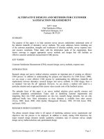
Drillstring Components
• The components of drillsting:
1. Drill Pipe
2. Drill Collar
3. Accessories including:
- HWDP
- Stabilizers
- Reamer
- Directional control equipment
Figure 1: Drillstring Components
5
Drill Pipe Selection
Table 1: DP grade and yield strength
Grade
•
•
Minimum Yield
Strength, psi
Letter Designation
Alternate
Designation
D
D-55
55,000
E
E-75
75,000
X
X-95
95,000
G
G-105
105,000
S
S-135
135,000
Only grade E, G and S are actually used in oilwell drilling.
API RP7G established guidelines for Drill Pipe as follows:
- New = no wear, never been used
- Premium = uniform wear, 80% wall thickness of new pipe
- Class 2 = 65% wall thickness of new pipe
- Class 3 = 55% wall thickness of new pipe
6
Tool Joints
• Tool joints are screw-type connectors that
join the individual joints of drillpipe.
• All API tool joints have minimum a yield
strength of 120,000 psi.
7
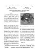
Washout in Drillstrings
• Tool joint failure is one of the main causes of
fishing jobs in drilling industry. This failure is
due entirely to the joint threads not holding or
not being made properly.
Figure 2: Make Up Torque
8
Washout in Drillstrings
• Washout can also develop due to cracks develop within
drill pipe due to severe drilling vibrations.
• Washout are usually detected by a decrease in the
standpipe pressure, between 100 – 300 psi over 5 – 15
minutes.
• The life of tool joints can be tripled if the joints if hardfaced
with composites of steel and tungsteen carbide.
9
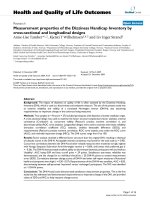
Approximate Weight of DP
and Tool Joint
• Nominal weight of DP is always less than the actual
weight of DP and tool joint because of the extra
weight added by tool joint and due to extra metal
added at the pipe ends to increase the pipe
thickness.
Figure 3: Tool joint dimension
10
Approximate Weight of DP
and Tool Joint
• Calculations of approximate weight of tool joint and DP:
a)
Approximate adjusted weight of DP Plain end weight
b)
upset weight
29.4
Approximate adjusted weight of tool jo int 0.222 x L D 2 d 2
Where :
0.167 x D 3 D 3TE 0.501 x d 2 x D DTE
L = combined length of pin and box (in)
D = outside diameter of pin (in)
d = inside diameter of pin (in)
DTE = diameter of box at elevator upset (in)
11
Approximate Weight of DP
and Tool Joint
c)
Approximate adjusted weight of DP assembly
approx. adjusted wt . DP x 29.4 approx. wt . tool jo int
29.4 tool jo int adjusted length
where,
tool jo int adjusted length
L 2.253 x D DTE
ft
12
12
Tool Joint Dimension
Table 2: Tool joint dimension table
13
Approximate Weight of DP
and Tool Joint
•
Example
calculate the approximate weight of tool joint and DP assembly for 5 in OD, 19.5 lb/ft Grade
E DP having a 6.375 in OD, 3.5 in ID. With NC50 tool joint. Assume the pipe to be
internally-externally upset (IEU) and the weight increased due to upsetting to be 8.6 lb.
•
Solution
Referring to Table 2, NC50, 6.375 in OD, 3.5 in ID tool joint for 19.5 lb/ft nominal weight DP
is available in grade X95
Thus
L = 17 in ; DTE = 5.125 in
D = 6.375 in ; and d = 3.5 in
14
Approximate Weight of DP
and Tool Joint
a) Approximate adjusted weight of Tool Joint
0.222 x 17 6.375 3.5 0.167 x 6.375
0.222 x L D 2 d 2 0.167 x D 3 D 3TE 0.501 x d 2 x D DTE
2
2
3
5.1253 0.501 x 3.52 x 6.375 5.125
120.27 lb
b). Approximate adjusted weight of Drill Pipe
plain end weight
upset weight
29.4
2
1
8 .6
5 4.276 2 x
x 489.5
4
144
29.4
17.93 0.293 18.22 lb / ft
15
Approximate Weight of DP
and Tool Joint
Adjusted length of tool joint:
L 2.253 x D DTE 17 2.253 x 6.375 5.125
1.651
12
12
c) Hence, approximate weight of tool joint and DP assembly :
18.22 x 120.27
21.2 lb / ft
1.651 29.4
16
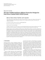
Drill Collar (DC) Selection
• There are two types of DC :
- Slick DC
- Spiral DC
• In areas where differential sticking
is a possibility spiral DC should be
used in order to minimize contact
area with formation.
Figure 4:Type of Drill Collars
17
Drill Collar (DC) Selection
Table 2: Drill Collar & Hole Size
18
Procedure for Selecting DC
1) Determine the Buoyancy Factor (BF) of the mud weight:
MW = mud weight, ppg
MWof a gallon of steel, ppg
65.5
BF =1weight
65.5
2) Calculate the required collar length to achieve desired WOB:
WOB = weight on bit, lbf (x1000)
Wdc = DC weight in air, lb/ft
WOB
0.85
safety
DC=Length
factor
0.85
x BFdimensionless
x Wdc
BF = buoyancy
factor,
3) For directional well:
I = well inclination
DC Length
DC Length vertical
cos I
19
Bending Strength Ratio (BSR)
• Bending strength ratio defined as the ratio of
relative stiffness of the box to the pin for a
given connection.
• Large OD drill collars provide greater stiffness
and reduce hole deviation problem.
20