Chapter 5 small signal midfrequency JFET
Bạn đang xem bản rút gọn của tài liệu. Xem và tải ngay bản đầy đủ của tài liệu tại đây (294.15 KB, 10 trang )
CHAPTER 5: Small-Signal Midfrequency FET
Val de Loire Program p.67
CHAPTER 5:
SMALL-SIGNAL MIDFREQUENCY FET
Table of Contents
5.1. INTRODUCTION 68
5.2. SMALL-SIGNAL EQUIVALENT CIRCUITS FOR THE FET 68
5.3. CS AMPLIFIER ANALYSIS 70
5.4. CD AMPLIFIER ANALYSIS 72
5.5. CG AMPLIFIER ANALYSIS 74
Table of Figures
Fig. 5.1 Drain charactersistics 69
Fig. 5.2 Small-signal models for the CS FET 70
Fig. 5.3 CS Amplifier 71
Fig. 5.4 CD Amplifier 73
Fig. 5.5 CG Amplifier 75
CHAPTER 5: Small-Signal Midfrequency FET
Val de Loire Program p.68
CHAPTER 5:
SMALL-SIGNAL MIDFREQUENCY FET
5.1. INTRODUCTION
In this chapter, all voltage and current signals are considered to be in
the midfrequency range, where all capacitors appear as short circuits.
There are three basic FET amplifier configurations: the common-
source (CS), common-drain (CD) or source-follower (SF), and common-
gate (CG) configurations. The CS amplifier, which provides good voltage
amplification, is most frequently used. The CD and CG amplifiers are
applied as buffer amplifiers (with high input impedance and near-unity
voltage gain) and high-frequency amplifiers, respectively.
5.2. SMALL-SIGNAL EQUIVALENT CIRCUITS FOR THE FET
CHAPTER 5: Small-Signal Midfrequency FET
Val de Loire Program p.69
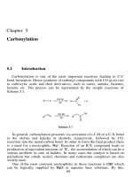
Fig. 5-1 Drain charactersistics
From the FET drain characteristics, it is seen that if
D
i
is taken as
the dependent variable, then
,
D GS DS
i f v v
For small excursions (ac signals) about the Q point,
D d
i i
; thus,
application of the chain rule:
1
d D D m gs ds
ds
i i di g v v
r
Where
m
g
and
ds
r
are defined as follows:
Transconductance:
D D
m
GS GS
Q Q
i i
g
v v
Source-drain resistance:
1
D D
ds DS DS
Q Q
i i
r v v
or
DS DS
ds
D D
Q Q
v v
r
i i
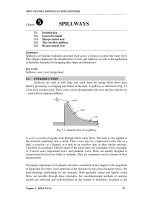
As long as the JFET is operated in the pinchoff region,
0
G g
i i
, so
that the gate acts as an open circuit. This leads to the current-source
equivalent circuit. Either of these models may be used in analyzing an
amplifier, but one may be more efficient than the other in a particular
circuit.
CHAPTER 5: Small-Signal Midfrequency FET
Val de Loire Program p.70
Fig. 5-2 Small-signal models for the CS FET
5.3. CS AMPLIFIER ANALYSIS
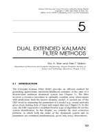
A simple common-source amplifier is shown in Fig. 5-3(a) and its
associated small-signal equivalent circuit is displayed in Fig. 5-3(b).
Source resistor
s
R
is used to set the Q point but is bypassed by
s
C
for
midfrequency operation.
CHAPTER 5: Small-Signal Midfrequency FET
Val de Loire Program p.71
Fig. 5-3 CS Amplifier
Example 5.1 In the CS amplifier, let
3
D
R k
,
60
,
30
ds
r k
.
(a) Find an expression for the voltage-gain ratio
o
v
i
v
A
v
.
(b) Evaluate
v
A
using the given typical values.
CHAPTER 5: Small-Signal Midfrequency FET
Val de Loire Program p.72
Solution
(a) By voltage division,
D
o gs
D ds
R
v v
R r
Substitution of
gs i
v v
and rearrangement give :
o D
v
i D ds
v R
A
v R r
(b) The given values lead to
5.45
v
A
Where the minus sign indicates a
0
180
phase shift between
i
v
and
o
v
.
5.4. CD AMPLIFIER ANALYSIS
CHAPTER 5: Small-Signal Midfrequency FET
Val de Loire Program p.73
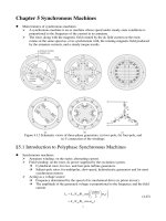
Fig. 5-4 CD Amplifier
A simple common-drain (or source-follower) amplifier is shown in
Fig. 5-4(a); its associated small-signal equivalent circuit is given in Fig.
5-4(b), where the voltage-source equivalent of Fig. 5-2(b) is used to
model the FET.
Example 5.2 In the CD amplifier, let
5
S
R k
,
60
,
30
ds
r k
.
(a) Find an expression for the voltage-gain ratio
o
v
i
v
A
v
.
(b) Evaluate
v
A
using the given typical values.
Solution
(a) By voltage division,
/ 1 1 1
S gd
S
o gd
S ds S ds
R v
R
v v
R r R r
CHAPTER 5: Small-Signal Midfrequency FET
Val de Loire Program p.74
Replacement of
gd
v
by
i
v
and rearrangement give
1
o S
v
i S ds
v R
A
v R r
(b) Substitution of the given values leads to
0.895
v
A
Note that the gain is less than unity; its positive value indicates that
o
v
and
i
v
are in phase.
5.5. CG AMPLIFIER ANALYSIS
Its small-signal equivalent circuit, incorporating the current-source
model of Fig. 5-2(a), is given:
(a) CG amplifier
CHAPTER 5: Small-Signal Midfrequency FET
Val de Loire Program p.75
(b) Small-signal equivalent circuit
Fig. 5-5 CG Amplifier
Example 5.3 In the CG amplifier, let
1
D
R k
,
3
2 10
m
g S
,
30
ds
r k
.
(a) Find an expression for the voltage-gain ratio
o
v
i
v
A
v
.
(b) Evaluate
v
A
using the given typical values.
Solution
(a) By KCL,
r d m gs
i i g v
. Applying KVL around the outer loop
gives:
o d m gs ds gs
v i g v r v
But
gs i
v v
and
o
d
D
v
i
R
; thus
o
o m i ds i
D
v
v g v r v
R
CHAPTER 5: Small-Signal Midfrequency FET
Val de Loire Program p.76
And :
1
m ds D
o
v
i D ds
g r R
v
A
v R r
(b) Substitution of the given values yields
1.97
v
A