Transmitter
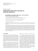
Bạn đang xem bản rút gọn của tài liệu. Xem và tải ngay bản đầy đủ của tài liệu tại đây (1.93 MB, 75 trang )
Level 1 - TransmitterRMT Training - 05 /98
1
Level 1
Fundamental Training
Fundamental Training
Level 1 - TransmitterRMT Training - 05 /98
2
Topics: Slide No:
•
Types of Transmitter Outputs 3 - 4
•
Analog Transmitter 5 - 7
•
Smart Transmitter 8 - 22
•
Fieldbus Transmitter 23 - 72
❒
Similarity between FF & PA
❒
Difference between FF & PA
❒
Benefits of FF against PA
•
Exercise 73 - 75
Contents
Contents
FF = Foundation Fieldbus
PA = Profibus
Level 1 - TransmitterRMT Training - 05 /98
3
Standard current
or voltage signal
(ANALOG)
Standard current or
voltage & digital signals
(SMART)
Only high speed
digital signals
(FIELDBUS)
Transducer
Transducer
Output Signal
Input
Signal
Process Pressure
Transmitter
Transmitter
Sensing element +
Electrical Circuitry
Analog/Smart/Fieldbus
Electronics
(To convert mechanical to
useable electrical signal)
(To translate useable
electrical signal to
standard electrical signal)
Transmitter Overview
Transmitter Overview
Level 1 - TransmitterRMT Training - 05 /98
4
Types of Transmitter Outputs
Types of Transmitter Outputs
❒
Analog Transmitters
–
Pure Analog Signal
–
4-20 mA or 1-5V or 3-15 psi pneumatic signal
❒
Smart Transmitters
–
Digital communication (diagnostic signal) superimposed on
analog signal (4-20 mA or 1-5V)
❒
Profibus Transmitters
–
High Speed Digital signal only
❒
Foundation Fieldbus Transmitters
–
High Speed Digital signal only
–
Control in the Field functionality
Level 1 - TransmitterRMT Training - 05 /98
5
Analog Transmitter Overview
Analog Transmitter Overview
Zero
Span
Pressure
Sensor
Signal
Conditioning
Standard
Output
Signal
Pressure Input Signal
Transducer
Capacitance /
mV Signal
Eg). Output = 4-20 mA current signal only
•
Analog transmitter is made up of two basic component:
»
Sensor Module
»
Analog Electronics
•
Signal from sensor module is amplified & translated into standard
current or voltage signal by the electronics
Level 1 - TransmitterRMT Training - 05 /98
6
How Analog Transmitters Works ?
How Analog Transmitters Works ?
4-20 mA
Current Only
Amplified
Signal
Transducer
Transducer
Output Electronics
Output Electronics
Loop wire
Loop wire
pair
pair
(Power
(Power
Cable)
Cable)
Cable Link
Cable Link
uF
PV
set 4 mA
value
set 20 mA
value
❏
Sensor registers process variable.
Zero Pot
Output
Span Pot
Sensor
Block
Signal Conditioning
Sensor
Circuit
Board
❏
Sensor board outputs a corresponding electrical signal to
output electronics.
❏
Signal conditioned & translated to a standard current signal
❏
Zero & Span Pots are used to set operating range.
Level 1 - TransmitterRMT Training - 05 /98
7
4-20 mA Current Loop
4-20 mA Current Loop
The voltage or current in the wire pair represents one
process variable.
4 to 20 mA
4 to 20 mA
250
Ω
250
Ω
1 - 5 V
To DCS, Recorders
1 - 5 V
To Control Room Device
4 - 20 mA
Analog
Transmitter
Field Indicator
Power
Supply
Current Loop
Control Loop
Level 1 - TransmitterRMT Training - 05 /98
8
Smart Transmitter
Smart Transmitter
Eg). Output = 4-20 mA current & Digital HART Signal
Module Temperature
Sensor
A/D
D/A
Communications
µ
Pressure
Sensor
EEPROM
Standard
Output Signal
Pressure Input Signal
Transducer
Capacitance /
mV Signal
Resistance
Data
•
Smart transmitter is an intelligent device made up of modems,
microprocessor and memory which allow :
»
Remote Communication
»
Diagnostics self-test functions
Level 1 - TransmitterRMT Training - 05 /98
9
Communication
4-20 mA & digital
communication
signal
Digital; PV +
Term. Temp
Values
Digital; corrected PV
Value
mV/uF
How Smart Transmitter Works ?
How Smart Transmitter Works ?
Sensor Module
Sensor Module
Smart Electronics
Smart Electronics
STORES:
•
Correction Coefficient
•
Module Information
Measures
ambient/Terminal
temp.
STORES:
•
Sensor Performance Curve
•
Range Values
•
Transmitter Configuration
PV
Cable
Cable
Link
Link
Electronics + Memory
Temperature
Sensor
Memory
A/D
µ
D/A
Sensor
Block
Bell 202 Physical Layer
Loop wire
Loop wire
pair
pair
(Power
(Power
Cable)
Cable)
Level 1 - TransmitterRMT Training - 05 /98
1
0
Analog vs Smart Transmitter
Analog vs Smart Transmitter
Smart
Smart
Transmitter
Transmitter
Analog
Analog
Transmitter
Transmitter
•
Analog output follow sensor
output instantaneously.
•
Analog output will be a
continuous curve.
•
Magnitude of sensor output
is sampled multiple times per
second to give discrete
values.
•
Analog output will undergo
small step change with
respect to sensor output.
A/D
Conversion
D/A
Conversion
4–20 mA
Output
Pressure
Input
4–20 mA
Output
Sampling
Real Time vs Sampling
Real Time vs Sampling
Level 1 - TransmitterRMT Training - 05 /98
1
1
HART
HART
®
®
Protocol
Protocol
20 mA
4 mA
Analog Output representing
process variable
HART protocol uses a frequency shift keying based on
Bell 202 physical layer to superimpose digital
communication on to the 4 - 20 mA current loop.
1200 Hz
H
H
ighway
ighway
A
A
ddressable
ddressable
R
R
emote
emote
T
T
ransducer
ransducer
Average modulating
current signal is
“ZERO”
Therefore HART protocol does NOT affect 4-20 mA signal
Digital
Communications
(HART Protocol)
1200 Hz
2200 Hz
Binary Status
Freq. Shift
“1”
“0”
2200Hz
+0.5 mA
–0.5 mA
0 mA
•
An open protocol
»
Users are not locked into a single supplier
Users are not locked into a single supplier
Level 1 - TransmitterRMT Training - 05 /98
1
2
4-20 mA Current Loop
4-20 mA Current Loop
The voltage or current in the wire pair represents one
process variable.
4 to 20 mA
4 to 20 mA
250
Ω
250
Ω
1 - 5 V
To DCS, Recorders
1 - 5 V
To Control Room Device
4 - 20 mA
Smart
Transmitter
Field Indicator
Power
Supply
Current Loop
Control Loop
Modulating Current
Communication Signal
Level 1 - TransmitterRMT Training - 05 /98
1
3
HART Communications
HART Communications
Modulating Voltage Communication Signal
Modulating Current
Communication Signal
Power
Supply
FIELD
TERMINALS
+
-
COMM TEST
Z
S
Minimum
Minimum
250 Ohms !
250 Ohms !
Average HART voltage
signal = ±0.3 V
But HART Circuit
recognize at least ±0.125 V
as a valid signal
4 - 20 mA
4 - 20 mA
To Establish
Communication
with HART
Communicator
E = I R
±0.5 mA * 250Ω
= ±0.125 V
Communication signal riding on 4-20 mA Analog signal
Communication signal riding on 4-20 mA Analog signal
Physical layer = BELL 202 FSK
Transmission Rate = 1.2kbit/s
Level 1 - TransmitterRMT Training - 05 /98
1
4
Remote Communication with HART protocol
Remote Communication with HART protocol
HART
communicator
can be
connected to any
points in the
loop having at
least 250
Ω
Chart
Recorder
Control System
Junction Box
Marshaling Panel
Power
Supply
Fuse
Box
Where to establish
communication with the
Smart Transmitter?
150Ω
100Ω
Level 1 - TransmitterRMT Training - 05 /98
1
5
HART Communicator for Smart Transmitter
HART Communicator for Smart Transmitter
SMART
Transmitter
Memory
Module
Memory
Data
Pack
275
Memory
Stores
configurations for
future use & DDs
Working memory
Working memory
Holds the connected
transmitter’s
configuration
Optional, holds transmitter
configurations for future use
Configuration
data stored in
the electronics
Communicator MUST hold the Device Descriptor files for that
Communicator MUST hold the Device Descriptor files for that
particular Device Model to establish communication.
particular Device Model to establish communication.
Communicator
•
Download DDs
»
Device Version.
»
Software Rev.
•
Field Upgrade-able
»
Latest device versions
& software revisions
can be added-on for
advanced functions.
Level 1 - TransmitterRMT Training - 05 /98
1
6
Power
Supply
1 2 3 - - - - - - - - - - - - 15
Assigned
Polling
Address
via
Communicator
4 mA
Stand-alone
Address = 0
4-20 mA + Digital Comm. Signal
250Ω
C
o
m
m
u
n
i
c
a
t
e
C
o
m
m
u
n
i
c
a
t
e
Only Digital Communication Signals
Poll
Address
2
Poll
Address
15
Multidropping is possible with
Multidropping is possible with
Digital Transmitters
Digital Transmitters
Maximum 15 HART devices can be multi-dropped.
Level 1 - TransmitterRMT Training - 05 /98
1
7
A
A
sset
sset
M
M
anagement
anagement
S
S
olution for Smart Devices
olution for Smart Devices
•
Asset Managment’s on-line
communications and
diagnostics provides
Maintenance & Engineering
the tools to efficiently
Manage Plant Assets!
Level 1 - TransmitterRMT Training - 05 /98
1
8
4-20 mA Loop
4-20 mA Loop
4-20 mA Loop
MULTIPLEXER
Can tap
32 Smart
Devices
MULTIPLEXER MULTIPLEXER
Can Multi-drop
CONVERTER
RS485
RS232
AMS Work Station
Can take up to
1500 Smart
Devices
Call Device by
Tag Number
DC Power
HART
device
METER
DC Power
HART device
METER
DC Power
HARTdevice
METER
AMS On-Line with Smart Transmitters
AMS On-Line with Smart Transmitters
AMS’s On-Line
Level 1 - TransmitterRMT Training - 05 /98
1
9
RS485/232 converter
MUX
ELCO
Cable
ELCO board
(Each board can tap
devices)
AMS Wiring Configuration
Wiring configuration
Wiring configuration
(Each MUX can
tap 32 devices)
Marshalling Panel
T
o
M
u
l
t
ip
l
e
x
e
r
Two set of ELCO cable
connect to ELCO boards
Incoming cable
from
field devices
To DCS
I/O cards
AMS
Workstation
Level 1 - TransmitterRMT Training - 05 /98
2
0
Smart Transmitter performs continuous diagnostics
Smart Transmitter performs continuous diagnostics
Diagnostic Information:
Diagnostic Information:
Normal Operating Range
Analog
Output
(mA)
204
Process Variable
Out of Range
20.83.9
Hardware Alarm
22
3.75
LOW HIGH
–
Hardware Failure Alarm
•
HIGH or LOW ⇒ User selectable by a jumper switch on the electronics
•
During failure ⇒ Output current fixed at either HIGH or LOW value
–
Process Alarm
•
Pressure drop below 4 mA point ⇒ Output current fixed at 3.9 mA
•
Pressure rise above 20 mA point ⇒ Output current fixed at 20.8 mA
•
Alarm message displayed
Level 1 - TransmitterRMT Training - 05 /98
2
1
•
Process Variable Reading
0 200
4 mA
20 mA
Can read the Process Variable when the
4–20 mA points are exceeded
•
Multiple Digital Outputs
»
Primary = Digital representation of Process Pressure
»
Secondary = Temperature inside Sensor Module
»
3rd = Not used on this Model
»
4th = Not used on this Model
Advantages of Smart Transmitter
Advantages of Smart Transmitter
140
PV = 40 psi
AO = 3.9 mA
PV = 160 psi
AO = 20.8 mA
80
Level 1 - TransmitterRMT Training - 05 /98
2
2
Benefits of Smart Transmitter Against
Benefits of Smart Transmitter Against
Analog Transmitter
Analog Transmitter
The digital format of the smart transmitter makes
The digital format of the smart transmitter makes
the following characteristics possible:
the following characteristics possible:
•
Higher accuracy
•
More Features
•
Wider Rangeability
•
Simplified Maintenance
•
Easier Commissioning
•
Multiple Sensor Readout
•
Better Electronic Stability
Level 1 - TransmitterRMT Training - 05 /98
2
3
•
Can be used for control
applications:
❒
pressure, temperature,
level & flow
•
Supports Intrinsic Safety (I.S.) with
bus powered devices
Hazardous
Hazardous
Area
Area
Safe area
Safe area
1
2
k
T
SB
T
PCPS
Control System
Fieldbus Application
Fieldbus Application
FF
PA
Level 1 - TransmitterRMT Training - 05 /98
2
4
Terminator
Terminator
Junction
Boxes
Operator
Interface
Configurator
Local
Operator
Interface
Power
Supply
9~32 V
Couplers
H1
Segment 1
Power
Filter
Power
Filter
Fieldbus Network Standard
Fieldbus Network Standard
•
IEC 1158-2 Standard
FF
PA
Level 1 - TransmitterRMT Training - 05 /98
2
5
Control Highway
Fieldbus I/O
Junction Box
Point to Point
Point to Point Branch
Branch
Daisy Chain
Daisy Chain
Tree
Tree
Fieldbus Supports Multiple Topology
Fieldbus Supports Multiple Topology
•
Topology
Topology
describes the Shape of the Network
FF
PA