CAN communication for vehicle emission control systems article
Bạn đang xem bản rút gọn của tài liệu. Xem và tải ngay bản đầy đủ của tài liệu tại đây (267.97 KB, 7 trang )
Center for Automotive Science & Technology
at Weber State University
Center for Automotive Science & Technology at Weber State University
2403 University Circle
Ogden, UT 84408-2403
Voice (801) 626-7803
Fax: (801) 626-6686
Note: A chart that details which
communication protocols are used by
the vehicle manufacturers is freely
available for download at
Select the Public
Files link (currently on the left side of
the web page) and then select the link
for Current and Future Use of CAN.
On the right side of the page will be
links to various files that detail
communication protocols used by
Make, Model and Year since 1996.
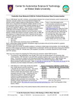
Controller Area Network (CAN) for Vehicle Emissions Data Communication
Prior to 1996 Model Year (MY) vehicles, communication between the on-board emissions control module and an
off-board computer system was not standardized between the
different vehicle Original Equipment Manufacturers (OEMs). In fact,
there was no requirement for federally certified vehicles to even
have emissions data communication available between an on-board
and off-board computer system. With the advent of On-Board
Diagnostics (OBD) for 1996 and newer vehicles, emissions related
serial data communication between the emissions control
module/modules (generally referred to as the Powertrain Control
Module or PCM) and off-board computer systems such as OBD I/M
test equipment or diagnostic scan tools is required and has been
limited to 3 general communication protocols, each with variations
possible within the protocol:
• SAE J1850
• ISO 9141
• ISO 14230 (more commonly known as KWP2000)
Note: A Serial Data Voltage Waveform Comparison page is provided at the end of this article for a general
reference of each protocol type.
To further reduce the number of possible variations in emissions related data communication, the Controller Area
Network (CAN) protocol is required to be implemented on passenger vehicles and light duty trucks by the 2008 MY.
A small number of 2003 MY vehicles were CAN equipped, but phase in is actually required from 2004 through
2007 MY vehicles.
There are many reasons for adapting the CAN protocol for emissions related OBD functions:
• The protocol is well established; even though CAN is just now being phased in for emissions data
communication, CAN has been in use with other computer systems, both on and off the vehicle for many
years. The protocol is based on the International Standards Organization (ISO) 11898 standard with
specific automotive application standards in the Society of Automotive Engineers (SAE) J2284
Recommended Practice documents. Refer to
www.sae.org
www.iso.org and for the
standards and other detailed information on the CAN protocol.
• CAN allows for a wide range of data bus speeds:
from 10,000 bits per second (10k bit/s) to
1,000,000 bits per second (1M bit/s). This means
the CAN protocol is able to accommodate the
needs for faster data transmission rates as well as
increased amounts of data. Coinciding with the
CAN protocol phase in, federal EPA and the
California Air Resources Board (CARB) are
requiring vehicle manufacturers to include
additional data parameters to be transmitted. The
specifics of these requirements can be found at
the CARB website:
/> under Final Regulation Order
Section 1968.2.
• CAN incorporates many of the positive features other protocols have used, such as:
Bit Rate Nominal Bit-Time (microseconds)
1 Mbit/sec 1µS
500 kbit/
s
2µS
250 kbit/
s
4µS
125 kbit/
s
8µS
20 kbit/s 50µS
10 kbit/s 100µS
General Comparison of Bit Rate and Bit Times
Note: other bit rate and times are also available for use
within the CAN protocol
10/31/2005
Page 2
5 volts
CAN_H
3.5 volts Dominant
Bit
2.5 volts Recessive Recessive
Bit Bit
1.5 volts Dominant
Bit
0 volts CAN_L
TIME
0 = Dominant
1 = Recessive
o Message Prioritization/Bus Arbitration (the module with the highest priority message controls data
transmission until that message is complete, then the module with the next priority message
transmits)
o Multicast reception (one module sends a message that several other modules use)
o Remote data request (one module requests information from another module)
o Redundant data circuits for increased circuit fault tolerance capability and superior noise filtering
capability
• CAN also includes advanced features such as:
o Module Auto-Off if the module becomes faulty and may possibly disrupt communication
o Additional modules can be added to the network without an entire system reconfiguration
o 3 different voltage states that represent 0 and 1 data bits on two circuits for redundancy (increased
fault tolerance) and increased noise filtering capabilities
Changes to hardware and software of off-board computer systems for CAN compatibility are required because of
the addition of the two CAN data circuits in the Data Link Connector (DLC), voltage states used to transmit data
and the amount of time per data bit:
• Prior to CAN, DLC terminals 6 & 14 were open for any use by the vehicle manufacturers (some restrictions
apply – for details refer to SAE J1962), but as CAN is implemented on the vehicle for emissions data
communication, DLC terminal 6 is reserved for the CAN High (CAN_H or CAN+) circuit and terminal 14 is
reserved for the CAN Low (CAN_L or CAN-) circuit. Since not all OBD I/M test equipment or scan tool
cables were constructed with these two circuits, older cables may have to be replaced with updated cables
that have the appropriate circuitry.
Important note:
Terminals 6 and 14 are associated with the CAN communication network responsible for
transmitting emissions related data. There may be other non-emissions related CAN networks on the
vehicle that connect to the DLC at other terminals.
• In the past, data protocols used a 0 volt state and then a
voltage high state; some protocols use 5 volts, other protocols
use 7 volts while others use 12 volts or system voltage. The
high speed CAN protocol uses 2.5 volts to represent a
recessive bit which is translated as a 1 data bit. A 0 data bit is
represented by a dominant bit; on the CAN_H circuit a
dominant bit is at 3.5 volts and on the CAN_L circuit the
dominant bit is at 1.5 volts. Note: CAN voltage values
referenced in this article are based on nominal values as listed
in ISO 11898. Each circuit has a range of acceptable voltage
levels and the voltage difference between CAN_H and CAN_L
during a dominant bit can range from 1.2 volts to 3.0 volts with 2.0 volts being specified as nominal.
• To achieve higher speed communication, the amount of time a voltage state exists to represent a data bit
must decrease. Many of the vehicle OEMs are using the 500,000 bit/second (500k bit/s) speed which
means the bit width in time is 2 microseconds (2 µS or 0.000002 seconds per bit – to verify this time, divide
1 by 0.000002 and the answer should be 500,000 bit/second or 1 divided by 500,000 = 0.000002
seconds/bit). Currently the 500k bit/s system is being referred to as “High Speed CAN” by many of the
vehicle manufacturers.
Because of these differences, hardware and software of the off-board computer systems must be updated for CAN
communicate to be possible.
CAN System Fault Tolerance
Since the CAN system is designed to use two circuits, it is possible to have the system communicate on only one
circuit (with degraded signal to noise ratio) if the other circuit has a fault such as an open, short to ground or B+.
This type of fault tolerance is recommended in the related CAN specifications, but fault tolerance is not required at
this time. As a result, some CAN systems will be able to communicate when a short to ground or power exists on
one or the other CAN circuit, yet other CAN systems will not be able to communicate when a fault condition exists
on either CAN circuit. Fault tolerant CAN systems may also be able to continue communications with the two CAN
circuits shorted together, similar to SAE J1850 Pulse Width Modulation (PWM) systems.
10/31/2005
Page 3
SAMPLE CAN WIRING DIAGRAM WITH TWISTED
PAIR CIRCUITS & TERMINATING RESISTORS
CAN System Configurations
Single and Two Circuit Systems
Within the CAN specifications there exists many
different possible configurations. For example,
manufacturers may have a single circuit CAN
application; however, these systems are currently
used with non-emissions related systems such as
headlamp or other body control modules, climate
control systems, radios, etc. The single circuit
systems operate at a speed much lower than the 500k
bit/s two circuit (CAN_H and CAN_L) system being
used for emissions related data transmission since
noise suppression and filtering capabilities with a
single wire are reduced. Some manufacturers also
use a two wire, lower speed CAN system for non-
emissions related data that is typically fault tolerant.
Non-emissions related CAN systems may also use
voltage levels other than those specified for the
emissions related high speed CAN systems.
Both the single and two data circuit configurations are
permitted to operate within a range of speeds (refer to
the General Comparison table listed previously) with
the understanding that a system will use only one
speed. Some vehicles use multiple CAN systems with
each operating at different speeds. To facilitate data
transfer from one system to another (for example;
vehicle speed (VS) data on the high speed system
may also be required by an audio system for vehicle
speed volume compensation), an interface module
(may also be referred to as a cross-over, gateway, or
bridge) is needed and becomes an integral part of both the high speed and low speed CAN data networks.
Shielded and Non-Shielded Twisted Pair
Systems
Different methods exist to help reduce
electromagnetic interference (EMI) from
components (other wiring, modules, coils,
etc.) near the CAN data circuit or circuits.
If the data circuits are shielded, the shield
drain circuit is to be grounded on only one
end that should be identified in the related
service information wiring diagram. This is
a typical requirement to avoid creating a
possible ground current loop between
modules with slightly different ground
voltage levels. As an important reminder, if
the shield or drain circuit becomes
damaged, proper repair procedures must be
followed to ensure shield and drain circuit
continuity is maintained so the signal to
noise ratio is correct.
Instead of using a shield and drain
configuration, the two circuit CAN system
may have the insulated circuits twisted
together throughout the wiring harness as a method to reduce EMI. By twisting the two circuits together, external
noise induced on the two circuits is effectively cancelled. The unshielded twisted pair must have a twist rate
Courtesy General Motors Co.
SAMPLE CAN WIRING DIAGRAM WITH TWISTED
PAIR CIRCUITS & TERMINATING RESISTORS
Courtesy DaimlerChrysler
10/31/2005
Page 4
between 33 and 50 twists/meter. If the twisted pair becomes damaged, repair procedures must include maintaining
the twist rate specified in the appropriate service information.
Terminating Resistors
Terminating resistors are used in the CAN system to
create a proper electrical load between the CAN_H
and CAN_L circuits. This load helps to reduce
electrical noise on the data circuits, which in turn
allows for a cleaner voltage signal.
Terminating resistors in the high speed CAN systems
are required to be 120 (actual specified range is
118 - 132) with lower speed CAN systems using
other resistance values. Split termination
implementations are allowed, which means there may
be more than two terminating resistors in the system
as long as the equivalent resistance between CAN_H
and CAN_L is between approximately 60 and 130.
Terminating resistors may be physically located inside
any of the modules connected to the CAN harness,
within a CAN junction connector, or the resistors may
be part of the wiring harness itself. Terminating
resistors may or may not be identified in the vehicle
wiring diagrams.
Because of the many variations related to terminating
resistor configuration and locations, communication
fault diagnostics for the specific vehicle must be
precisely followed. Do not attempt to conduct wiring
diagnostic fault isolation procedures such as voltage or resistance tests without the proper service information and
specifications.
CAN System Diagnosis
Diagnosing CAN communication errors requires the proper service information and diagnostic equipment. A CAN
compatible scan tool as well as appropriate service information which includes an accurate wiring diagram of the
CAN system being diagnosed should be considered essential. Always follow the appropriate fault isolation
procedures published by the vehicle manufacturer. The following diagnostic suggestions are not intended to
replace any vehicle manufacturer diagnostic procedure; rather, they are intended to supplement/enhance published
procedures for communication system diagnosis:
• Verify whether or not your diagnostic scan tool is able to communicate with the PCM. Important note:
If the
scan tool is able to communicate but the vehicle failed an OBD I/M test for no-communication, make sure
the next three steps are completed. Many scan tools do not require B+ at DLC pin 16 or ground at pin 4 or
pin 5 (ground must be present at one or the other) for communication, however, most OBD I/M test
equipment do require proper circuit functionality at pins 16, 4 and 5 for communication.
• Verify B+ is available at DLC pin 16; system voltage should be present at all times. Use a known good
ground (battery negative if possible) to make this measurement. The best way to verify circuit functionality
is to take voltage measurements while a scan tool is connected to the DLC, powered on if possible and
requesting data. The DLC may have to be backprobed (carefully) to gain access to each circuit for
diagnosis with the scan tool connected.
• Verify DLC pin 4 is properly grounded.
• Verify DLC pin 5 is properly grounded. After verifying proper ground at pin 5, use this circuit for reference
low during any data circuit voltage measurements since this is the communication network reference low.
• With the ignition key on and scan tool disconnected from the DLC, measure voltage at DLC pin 6 (CAN_H)
and pin 14 (CAN_L). If the communication circuits do not have a malfunction present, the measured
voltage on most systems will be rapidly fluctuating and will be between 1.5 volts and 3.5 volts. If a short to
ground exists, measured voltage will be lower than 1.5 volts and if a short to positive voltage exists the
measured voltage will be above 3.5 volts. Important note:
Some CAN networks may use a separate CAN
section for connection to off-board diagnostic computer systems such as scan tools or OBD I/M test
equipment (refer to the previous DaimlerChrysler diagram). These diagnostic CAN circuits may be inactive
until an off-board computer is connected to the DLC and requests data from CAN modules on the main
SAMPLE CAN WIRING DIAGRAM
WITH TERMINATING RESISTORS
Courtesy Toyota Motor Co.
10/31/2005
Page 5
network. Also, be aware that there are CAN systems that cause the CAN_H circuit to go to a steady 5 volt
state and the CAN_L circuit to go to a steady 0 volt state during idle conditions. Do not use communication
system diagnostic procedures that are not approved by the specific vehicle manufacturer. Be sure to follow
each diagnostic procedure correctly and under the proper operating conditions.
• With the ignition key off and the PCM connector disconnected, a circuit resistance test can be used to
determine if an open circuit exists between the PCM and DLC in either of the CAN data circuits.
Resistance measurements should be very low (typically less than 5 ohms), indicating circuit continuity is
good. If excessive resistance is measured, ensure the resistance test is not inadvertently measuring a
terminating resistor. Multiple circuit segments may need to be tested if other control modules are
positioned between the PCM and DLC (refer to the previous DaimlerChrysler and GM diagrams).
• A short to ground can also be identified through a resistance measurement between the CAN data circuits
and ground. Low resistance should not be measured between either CAN data circuit and ground.
Multiple circuit segments may need to be tested if control modules are positioned in series with each other
instead of connected in parallel to the network (refer to the previous GM diagram for a system with
modules connected in series and refer to the DaimlerChrysler and Toyota diagrams for systems wired in
parallel).
• A short to B+ can be identified by measuring voltage on the CAN data circuits with the ignition key on. If a
short to voltage exists, the measured voltage will be relatively steady and outside typical ranges. Separate
circuit segments may need to be tested individually to identify where the short to B+ actually exists.
• CAN circuits shorted together may also be identified by measuring resistance between the CAN_H and
CAN_L circuits with all associated modules disconnected from the CAN network. Resistance
measurements should not indicate circuit resistance values less than approximately 60 ohms. Always use
appropriate service information specifications for the vehicle being tested.
CAN systems bring many new and exciting possibilities for module and sensor evolution into further advanced
electronic systems which will play an important role in achieving continued efficiency improvements and reduced
emissions. CAN implementation will also bring new challenges as malfunctions occur with resulting symptoms,
some of which will be new and will require updated diagnostic procedures and thought processes. Already there
are many variations in CAN systems with each system having unique features. Diagnosis of each system must be
based on the proper use of correct and updated tools, service information and procedures.
10/31/2005
Page 6
Serial Data Voltage Waveform Comparison
Note: the information on this page is intended only as a general reference and comparison between the different
types of OBD compliant data communication protocols.
3.5 volts
1.5 volts
0001
Each bit equals 2 microseconds (µs)
24 µs
10100111
2.5 volts
5 volts
0 volts
CAN 500k bit/s
Bus +
Bus -
24 µs24 µs
48 µs
24 µs 24 µs
5 volts
5 volts
0 volts
1 data bit
0 data bit
J1850 PWM 41.6k bit/s
1 data bit
0 data bit
0 volts
J1850 VPW avg. 10.4k bit/s
64 µs 64 µs 128 µs
384 microseconds
0 data bit 0 data bit 1 data bit 1 data bit
0 volts
128 µs
7 volts
ISO 9141 10.4k bit/s
12 volts
0 volts
384 microseconds
96 µs
1 data bit0 data bit0 data bit
96 µs
1 data bit
96 µs96 µs
10/31/2005
Page 7
Chuck Gee
Training Developer and Instructor
Center for Automotive Science & Technology @ Weber State University
2403 University Circle
Ogden, UT 84408-2403
(801) 626-7803
The author wishes to acknowledge the contributions and support of the following individuals in writing this article:
Joe Grundvig of Weber State University General Motors Training Center, Rob Wilkes of Daimler-Chrysler Training
Organization, John Kelly of Weber State University Automotive Technology

