E 422 05 (2016)
Bạn đang xem bản rút gọn của tài liệu. Xem và tải ngay bản đầy đủ của tài liệu tại đây (124.96 KB, 5 trang )
Designation: E422 − 05 (Reapproved 2016)
Standard Test Method for
Measuring Heat Flux Using a Water-Cooled Calorimeter1
This standard is issued under the fixed designation E422; the number immediately following the designation indicates the year of
original adoption or, in the case of revision, the year of last revision. A number in parentheses indicates the year of last reapproval. A
superscript epsilon (´) indicates an editorial change since the last revision or reapproval.
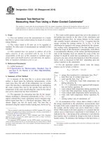
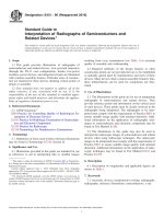
1. The water-cooled annular guard ring serves the purpose of
preventing heat transfer to the sides of the calorimeter and
establishes flat-plate flow. An energy balance on the system
(the centrally located calorimeter in Fig. 1) requires that the
energy crossing the sensing surface (A, in Fig. 1) of the
calorimeter be equated to the energy absorbed by the calorimeter cooling water. Interpretation of the data obtained is not
within the scope of this discussion; consequently, such effects
as recombination efficiency of the surface and thermochemical
state of the boundary layer are outside the scope of this test
method. It should be noted that recombination effects at low
pressures can cause serious discrepancies in heat flux measurements (such as discussed in Ref (1))3 depending upon the
surface material on the calorimeter.
1. Scope
1.1 This test method covers the measurement of a steady
heat flux to a given water-cooled surface by means of a system
energy balance.
1.2 The values stated in SI units are to be regarded as
standard. No other units of measurement are included in this
standard.
1.3 This standard does not purport to address all of the
safety concerns, if any, associated with its use. It is the
responsibility of the user of this standard to establish appropriate safety and health practices and determine the applicability of regulatory limitations prior to use.
2. Referenced Documents
3.3 For the particular control volume cited, the energy
balance can be written as follows:
2.1 ASTM Standards:2
E235 Specification for Thermocouples, Sheathed, Type K
and Type N, for Nuclear or for Other High-Reliability
Applications
E CAL 5 @ mCp ~ ∆T 0 2 ∆T 1 ! # /A
where:
ECAL =
m
=
Cp
=
∆T0 =
3. Summary of Test Method
3.1 A measure of the heat flux to a given water-cooled
surface is based upon the following measurements: (1) the
water mass flow rate and (2) the temperature rise of coolant
water. The heat flux is determined numerically by multiplying
the water coolant flow rate by the specific heat and rise in
temperature of the water and dividing this value by the surface
area across which heat has been transferred.
3.2 The apparatus for measuring heat flux by the energybalance technique is illustrated schematically in Fig. 1. It is a
typical constant-flow water calorimeter used to measure stagnation region heat flux to a flat-faced specimen. Other calorimeter shapes can also be easily used. The heat flux is
measured using the central circular sensing area, shown in Fig.
∆T1
=
T02
T01
T2
T1
=
=
=
=
A
=
(1)
energy flux transferred to calorimeter face, W·m−2
mass flow rate of coolant water, kg·s−1
water specific heat, J·kg−1·K−1,
T02 — T01 calorimeter water bulk temperature rise
during operation, K,
T2 — T1 = calorimeter water apparent bulk temperature rise before operation, K,
water exhaust bulk temperature during operation, K,
water inlet bulk temperature during operation, K,
water exhaust bulk temperature before operation, K,
water inlet bulk temperature before operation, K,
and
sensing surface area of calorimeter, m2.
3.4 An examination of Eq 1 shows that to obtain a value of
the energy transferred to the calorimeter, measurements must
be made of the water coolant flow rate, the temperature rise of
the coolant, and the surface area across which heat is transferred. With regard to the latter quantity it is assumed that the
surface area to which heat is transferred is well defined. As is
indicated in Fig. 1, the design of the calorimeter is such that the
heat transfer area is confined by design to the front or directly
heated surface. To minimize side heating or side heat losses, a
1
This test method is under the jurisdiction of ASTM Committee E21 on Space
Simulation and Applications of Space Technology and is the direct responsibility of
Subcommittee E21.08 on Thermal Protection.
Current edition approved April 1, 2016. Published April 2016. Originally
approved in 1971. Last previous edition approved in 2011 as E422 – 05 (2011).
DOI: 10.1520/E0422-05R16.
2
For referenced ASTM standards, visit the ASTM website, www.astm.org, or
contact ASTM Customer Service at For Annual Book of ASTM
Standards volume information, refer to the standard’s Document Summary page on
the ASTM website.
3
The boldface numbers in parentheses refer to the list of references at the end of
this test method.
Copyright © ASTM International, 100 Barr Harbor Drive, PO Box C700, West Conshohocken, PA 19428-2959. United States
1
E422 − 05 (2016)
FIG. 1 Steady-State Water-Cooled Calorimeter.
radiative heat-flux rates, then the surface reflectivity of the
calorimeter shall be measured over the wavelength region of
interest (depending on the source of radiant energy). If nonuniformities exist in the gas stream, a large surface area
water-cooled calorimeter would tend to smooth or average any
variations. Consequently, it is advisable that the size of the
calorimeter be limited to relatively small surface areas and
applied to where the heat-flux is uniform. Where large samples
are tested it is recommended that a number of smaller diameter
water-cooled calorimeters be used (rather than one large unit).
These shall be located across the heated surface such that a
heat-flux distribution can be described. With this, a more
detailed heat-flux measurement can be applied to the specimen
test and more information can be deduced from the test.
water-cooled guard ring or shroud is utilized and is separated
physically from the calorimeter by means of an air gap and low
conductivity bushing such as nylon. The air gap is recommended to be no more than 0.5 mm on the radius. Thus, if
severe pressure variations exist across the face of the
calorimeter, side heating caused by flow into and out of the air
gap will be minimized. Also, since the water-cooled calorimeter and guard ring operate at low surface temperatures
(usually lower than 100°C) heat losses across the gap by
radiant interchange are negligible and consequently no special
calorimeter surface gap finishes are necessary. Depending upon
the size of the calorimeter surface, large variations in heat flux
may exist across the face of the calorimeter. Consequently, the
measured heat flux represents an average heat flux over the
surface area of the water-cooled calorimeter. The water-cooled
calorimeter can be used to measure heat-flux levels over a
range from 10 kW/m2 to 60 MW/m2.
5. Apparatus
5.1 General—The apparatus shall consist of a water-cooled
calorimeter and the necessary instrumentation to measure the
heat transferred to the calorimeter. Although the recommended
instrumentation accuracies are state-of-the-art values, more
rugged and higher accuracy instrumentation may be required
for high pressure and high heat-flux applications. A number of
materials can be used to fabricate the calorimeter, but OFHC
(oxygen free high conductivity) copper is often preferred
because of its superior thermal properties.
4. Significance and Use
4.1 The purpose of this test method is to measure the heat
flux to a water-cooled surface for purposes of calibration of the
thermal environment into which test specimens are placed for
evaluation. If the calorimeter and holder size, shape, and
surface finish are identical to that of the test specimen, the
measured heat flux to the calorimeter is presumed to be the
same as that to the sample’s heated surface. The measured heat
flux is one of the important parameters for correlating the
behavior of materials.
5.2 Coolant Flow Measurement—The water flow rate to
each component of the calorimeter shall be chosen to cool the
apparatus adequately and to ensure accurately measurable rise
in water temperature. The error in water flow rate measurement
shall be not more than 62 %. Suitable equipment that can be
used is listed in Ref (2) and includes turbine flowmeters,
variable area flowmeters, etc. Care must be exercised in the use
of all these devices. In particular, it is recommended that
appropriate filters be placed in all water inlet lines to prevent
particles or unnecessary deposits from being carried to the
water-cooling passages, pipe, and meter walls. Water flow rates
and pressure shall be adjusted to ensure that no bubbles are
formed (no boiling). If practical, the water flowmeters shall be
placed upstream of the calorimeter in straight portions of the
piping. The flowmeter device shall be checked and calibrated
4.2 The water-cooled calorimeter is one of several calorimeter concepts used to measure heat flux. The prime drawback is
its long response time, that is, the time required to achieve
steady-state operation. To calculate energy added to the coolant
water, accurate measurements of the rise in coolant temperature are needed, all energy losses should be minimized, and
steady-state conditions must exist both in the thermal environment and fluid flow of the calorimeter.
4.3 Regardless of the source of energy input to the watercooled calorimeter surface (radiative, convective, or combinations thereof) the measurement is averaged over the surface
active area of the calorimeter. If the water-cooled calorimeter is
used to measure only radiative flux or combined convective2
E422 − 05 (2016)
6. Procedure
periodically. Pressure gages, if required, shall be used in
accordance with the manufacturer’s instructions and calibration charts.
6.1 It is essential that the environment be at steady-state
conditions prior to testing if the water-cooled calorimeter is to
give a representative measure of the heat flux.
5.3 Coolant Temperature Measurement—The method of
temperature measurement must be sufficiently sensitive and
reliable to ensure accurate measurement of the coolant water
temperature rise. Procedures similar to those given in Specification E235, Type K, and Ref (3) should be followed in the
calibration and preparation of temperature sensors. The bulk or
average temperature of the coolant shall be measured at the
inlet and outlet lines of each cooled unit. The error in
measurement of temperature difference between inlet and
outlet shall be not more than 61 %. The water temperature
indicating devices shall be placed as close as practical to the
calorimeter’s heated surface in the inlet and outlet lines.
However, care must be exercised so as not to place the
temperature sensors where there is energy exchange between
the incoming (cold) water and the outgoing (heated) water.
This occurs most readily at flow dividers and at the calorimeter
sensing surface. No additional apparatus shall be placed in the
line between the temperature sensor and the heat source. The
temperature measurements shall be recorded continuously to
verify that steady-state operation has been achieved. Reference
(2) lists a variety of commercially available temperature
sensors. Temperature sensors which are applicable include
liquid-in-glass thermometers, thermopiles, thermocouples, and
thermistors. During operation of the heat source, care should be
taken to minimize deposits on the temperature sensors and to
eliminate any possibility of sensor heating because of specimen
radiation to the sensor. In addition, all water lines should be
shielded from direct-flow impingement or radiation from the
test environment.
5.3.1 If at all practical a thermocouple shall be placed on the
water-cooled side of the heated calorimeter surface. Although
this surface temperature (water side) measurement is not used
directly in the calculation of heat flux it is necessary for the
calculation of the surface temperature (front face) used in the
correction of the measured heat flux to walls of different
temperatures.
6.2 After a sufficient length of time has elapsed to assure
constant mass flow of water as well as constant inlet and outlet
water temperature, place the system into the heat-source
environment. Steady-state operation has been assured if the
inlet and exhaust water temperature, and water flow rates are
steady and not changing with time. In particular the water flow
rates should not change during operation. After removing the
calorimeter from the environment, record the inlet water
temperature and flow rates so that they can be compared with
pretest values. Changes between pre- and post-test water
temperature rise may indicate deposit buildups on the calorimeter backface or cooling passages which may alter the results of
the measurement of energy transfer.
6.3 To ensure consistent heat-flux data, it is recommended
that measurements be repeated with the same apparatus. A
further check on the measurement of heat flux using a
water-cooled calorimeter would be to use a different mass flow
of water through the calorimeter for different test runs. No
significant difference in heat-flux measurements should be
noted with the change in water flow rate for different test runs.
7. Heat-Flux Calculation
7.1 The quantities as defined by Eq 1 shall be calculated
based on the bulk or average temperature rise of the coolant
water for each water-cooled section of the calorimeter. The
choice of units shall be consistent with the measured quantities.
7.2 Variance analyses of heat-source conditions shall provide a sound basis for estimation of the reproducibility of the
thermal environment. Refs (4) and (5) may provide a basis for
error analysis of the measurements.
8. Report
8.1 In reporting the results of the measurement tests, the
following steady-state data shall be reported:
8.1.1 Dimensions of the calorimeter configuration active
surface and guard ring,
8.1.2 Calorimeter coolant water flow rate,
8.1.3 Temperature rise of calorimeter coolant water,
8.1.4 Calculated heat flux,
8.1.5 Front surface temperature (if measured or calculated),
and
8.1.6 Variance of results.
5.4 Recording Means:
5.4.1 Since measurement of the energy transfer requires that
the calorimeter operate as a steady state device, all calculations
will use only measurements taken after it has been established
that the device has achieved steady operating levels. To assure
steady flow or operating conditions the above mentioned
parameters shall be continuously recorded such that instantaneous measurements are available to establish a measure of
steady-state operation. Wherever possible it is highly desirable
that the differential temperature (∆T) be made of the desired
parameters rather than absolute measurements.
5.4.2 In all cases, parameters of interest, such as water flow
rates and cooling water temperature rises should be automatically recorded throughout the measurement period. Recording
speed or sampling frequency will depend on the variations of
the parameters being recorded. When a strip chart recorder is
used, the response time of the recorder shall be 1 s or less for
full-scale deflection. Timing marks should be an integral part
of the recorder with a minimum requirement of 1/s.
9. Measurement Uncertainty
9.1 There are a number of methods that can be used for the
determination of measurement uncertainty. A recent summary
of the various uncertainty analysis methods is provided in Ref
(6). The American Society of Mechanical Engineers’
(ASME’s) earlier performance test code PTC 19.1-1985 (7) has
been revised and was replaced by Ref (8) in 1998. In Refs (7)
and (8), uncertainties were separated into two types: “bias” or
“systematic” uncertainties (B) and “random” or “precision”
uncertainties (S). Systematic uncertainties (Type B) are often
3
E422 − 05 (2016)
9.5.7 Positioning errors.
9.5.8 Angular errors.
(but not always) constant for the duration of the experiment.
Random uncertainties are not constant and are characterized
via the standard deviation of the random measurements, thus
the abbreviation ‘S.’
9.6 Additional uncertainty can be attributed to the engineering application of the thermocouple transducer to the
environment, or material, of interest. Specific examples include:
9.6.1 Contact between a thermocouple and its environment,
or thermal contact conductance between the bead and material.
The contact conductance must be characterized to analyze the
bead transient response versus the environment.
9.6.2 Radiation versus convective heat transfer of the environment versus heat transferred to the bead. The bead emissivity must be known or estimated for incident radiative
environment calculations.
9.6.3 Time response of the thermocouple bead (or probe)
versus the estimated transient thermal environment to be
measured to ensure the TC is not too slow to measure gradients
of interest.
9.6.4 Position location uncertainty of the TC junction must
be known to perform material response analysis. The uncertainty of temperature measurement location will propagate
error into material response calculations.
9.6.5 When using mineral-insulated, metal-sheathed
thermocouples, the TC wires are surrounded with the metal
sheath to keep the TC wires from shorting, melting, and so
forth. But in doing so, the TC measuring junction is insulated
from the environment being measured, and the measurement
will have some thermal lag. The TC thermal lag is increasingly
worse as the transient environment becomes faster.
9.2 ASME’s new standard (8) proposes use of the following
model:
1
U 95 5 6t 95 @ ~ B T /2 ! 2 1 ~ S T ! 2 # 2
(2)
where t95 is determined from the number of degrees of
freedom (DOF) in the data provided. For large DOF (that is, 30
or larger) t95 is almost 2. BT is the total bias or systematic
uncertainty of the result, ST is the total random uncertainty or
precision of the result, and t95 is “Student’s t” at 95 % for the
appropriate degrees of freedom (DOF).
9.3 This test method requires the measurement of water
flow rate, temperature difference, and sensing surface area. The
water flow rate measurement can be made with fundamentally
different methods such as differential pressure across an orifice
or an in-line turbine correlating vane velocity to flow rate. The
successful application of this test method requires the user to
perform an uncertainty analysis on the specific steady state
water flow rate instrument used ((9, 10). In the case of sensing
surface area, length measurement techniques with their uncertainties are well documented (10).
9.4 In the case of a temperature measurement ((9, 11)) with
a thermocouple, types of systematic uncertainties are mounting
errors, non-linearity, and gain. Less commonly discussed
systematic uncertainties are those that result from the sensor
design (that is, TC junction type) and coupling with the
environment. Types of random uncertainty are common mode
and normal mode noise.
9.7 It is important to realize that any transducer has finite
mass and heat transfer characteristics. Therefore, the thermocouple (for example) will read a temperature different from the
surface you are measuring. In a well-designed experimental
system the difference between the “true” temperature and the
TC reading can be reduced to acceptable values. Errors are not
zero or negligible, but acceptable from an uncertainty budget
perspective. The main point is uncertainty exists, and, it must
be quantified to produce meaningful data.
9.5 To quantify the total uncertainty of a measurement, the
entire measurement system must be examined. For a thermocouple measurement the following uncertainty sources must be
considered:
9.5.1 Thermocouple wire accuracy.
9.5.2 Thermocouple connectors.
9.5.3 Thermocouple extension cable.
9.5.4 Thermocouple mounting error (transient and steady).
9.5.5 Data acquisition system (DAS).
9.5.6 Conversion equation (mV to temperature).
10. Keywords
10.1 calorimeter; heat flux; heat transfer rate
REFERENCES
(1) Pope, R. B., Stagnation-Point Convective Heat Transfer in Frozen
Boundary Layers, AIAA Journal, Vol g, No. 4, April 1968, pp.
619–626.
(2) ISA Transducer Compendium, A Publication of Instrument Society of
America, Plenum Press, 1963.
(3) Considine, D. M., Process Instruments and Controls Handbook,
McGraw-Hill Book Co., Inc., 1957.
(4) Brownlee, K. A., Statistical Theory and Methodology in Science and
Engineering, John Wiley and Sons, Inc., New York, NY, 1960.
(5) Hald, A., Statistical Theory with Engineering Applications, John
Wiley and Sons, Inc., New York, NY, 1952.
(6) Dieck, R. H., “Measurement Uncertainty Models,” ISA Transactions,
Vol. 36, No.1, 1997, pp. 29–35.
(7) ANSI/ASME PTC 19.1-1985, “Part 1, Measurement Uncertainty,
Instruments and Apparatus,” Supplement to the ASME Performance
Test Codes, reaffirmed 1990.
(8) ASME PTC 19.1-1998, “Test Uncertainty, Instruments and
Apparatus,” Supplement to the ASME Performance Test Codes, 1998.
(9) Doebelin, E. O., Measurement Systems Application and Design,
McGraw-Hill, 1983.
(10) Holman, J.P., Experimental Methods for Engineers, McGraw-Hill,
1978.
4
E422 − 05 (2016)
(11) Manual on the Use of Thermocouples in Temperature Measurement,
ASTM Manual Series: MNL 12, Revision of Special Technical
Publication (STP) 470B, ASTM International, 1993.
(12) Coleman, H. W. and Steele, W. G., “Engineering Application of
Experimental Uncertainty Analysis,” AIAA Journal, Vol. 33, No. 10,
October 1995, pp. 1888–1896.
ASTM International takes no position respecting the validity of any patent rights asserted in connection with any item mentioned
in this standard. Users of this standard are expressly advised that determination of the validity of any such patent rights, and the risk
of infringement of such rights, are entirely their own responsibility.
This standard is subject to revision at any time by the responsible technical committee and must be reviewed every five years and
if not revised, either reapproved or withdrawn. Your comments are invited either for revision of this standard or for additional standards
and should be addressed to ASTM International Headquarters. Your comments will receive careful consideration at a meeting of the
responsible technical committee, which you may attend. If you feel that your comments have not received a fair hearing you should
make your views known to the ASTM Committee on Standards, at the address shown below.
This standard is copyrighted by ASTM International, 100 Barr Harbor Drive, PO Box C700, West Conshohocken, PA 19428-2959,
United States. Individual reprints (single or multiple copies) of this standard may be obtained by contacting ASTM at the above
address or at 610-832-9585 (phone), 610-832-9555 (fax), or (e-mail); or through the ASTM website
(www.astm.org). Permission rights to photocopy the standard may also be secured from the Copyright Clearance Center, 222
Rosewood Drive, Danvers, MA 01923, Tel: (978) 646-2600; />
5