Electric motor controls tutorial
Bạn đang xem bản rút gọn của tài liệu. Xem và tải ngay bản đầy đủ của tài liệu tại đây (661.74 KB, 24 trang )
1
ELECTRIC MOTOR CONTROLS
Once the proper motor is selected, understanding the many various control devices available and
their uses and limitations becomes an important part related to reliable operation and protection of
the motor and the personnel using the motor.
Motor Control Topics
There are four major motor control topics or categories to consider. Each of these has several
subcategories and sometimes the subcategories overlap to some extent. Certain pieces of motor
control equipment can accomplish multiple functions from each of the topics or categories.
C The four categories include:
1) Starting the Motor
Disconnecting Means
Across the Line Starting
Reduced Voltage Starting
2) Motor Protection
Overcurrent Protection
Overload Protection
Other Protection (voltage, phase, etc)
Environment
3) Stopping the Motor
Coasting
Electrical Braking
Mechanical Braking
4) Motor Operational Control
Speed Control
Reversing
Jogging
Sequence Control
• An understanding of each of these areas is necessary to effectively apply motor control
principles and equipment to effectively operate and protect a motor.
2
MOTOR STARTING
All motors must have a control device to start and stop the motor called a “motor controller”.
Motor Controller
A motor controller is the actual device that energizes and de-energizes the circuit to the motor so
that it can start and stop.
• Motor controllers may include some or all of the following motor control functions:
S starting, stopping, over-current protection, overload protection, reversing, speed
changing, jogging, plugging, sequence control, and pilot light indication.
S Controllers range from simple to complex and can provide control for one motor,
groups of motors, or auxiliary equipment such as brakes, clutches, solenoids, heaters,
or other signals.
Motor Starter
The starting mechanism that energizes the circuit to an induction motor is called the “starter” and
must supply the motor with sufficient current to provide adequate starting torque under worst case
line voltage and load conditions when the motor is energized.
• There are several different types of equipment suitable for use as “motor starters” but only
two types of starting methods for induction motors:
1. Across the Line Starting
2. Reduced Voltage Starting
Across the Line Starting of Motors
Across the Line starting connects the motor windings/terminals directly to the circuit voltage “across
the line” for a “full voltage start”.
• This is the simplest method of starting a
motor. (And usually the least expensive).
• Motors connected across the line are capable
of drawing full in-rush current and
developing maximum starting torque to
accelerate the load to speed in the shortest
possible time.
• All NEMA induction motors up to 200
horsepower, and many larger ones, can withstand full voltage starts. (The electric
distribution system or processing operation may not though, even if the motor will).
Across the Line Starters
3
Figure 26. Manual Starter
There are two different types of common “across the line” starters including
1. Manual Motor Starters
2. Magnetic Motor Starters
Manual Motor Starters
A manual motor starter is package consisting of a horsepower rated switch with one set of contacts
for each phase and corresponding thermal overload devices to provide motor overload protection.
• The main advantage of a manual motor starter is lower cost than a magnetic motor starter
with equivalent motor protection but less motor control capability.
• Manual motor starters are often used for smaller motors - typically fractional horsepower
motors but the National Electrical Code allows their use up to 10 Horsepower.
• Since the switch contacts remain closed if power is removed from the circuit without
operating the switch, the motor restarts when power is reapplied which can be a safety
concern.
• They do not allow the use of remote control or auxiliary control equipment like a magnetic
starter does.
Magnetic Motor Starters
A magnetic motor starter is a package consisting of a contactor capable of opening and closing a set
4
Figure 27. Magnetic Starter
of contacts that energize and de-energize the circuit to the motor along with additional motor
overload protection equipment.
C Magnetic starters are used with larger motors (required above 10 horsepower) or where
greater motor control is desired.
• The main element of the magnetic motor starter is the contactor, a set of contacts operated by
an electromagnetic coil.
S Energizing the coil causes the contacts (A) to close allowing large currents to be
initiated and interrupted by a smaller voltage control signal.
S The control voltage need not be the same as the motor supply voltage and is often low
voltage allowing start/stop controls to be located remotely from the power circuit.
• Closing the Start button contact energizes the contactor coil. An auxiliary contact on the
contactor is wired to seal in the coil circuit. The contactor de-energizes if the control circuit
is interrupted, the Stop button is operated, or if power is lost.
• The overload contacts are arranged so an overload trip on any phase will cause the contactor
to open and de-energize all phases.
Reduced Voltage Starting of Motors
Reduced Voltage Starting connects the motor windings/terminals at lower than normal line voltage
during the initial starting period to reduce the inrush current when the motor starts.
5
• Reduced voltage starting may be required when:
S The current in-rush form the motor starting adversely affects the voltage drop on the
electrical system.
S needed to reduce the mechanical “starting shock” on drive-lines and equipment when
the motor starts.
• Reducing the voltage reduces the current in-rush to the motor and also reduces the starting
torque available when the motor starts.
• All NEMA induction motors can will accept reduced voltage starting however it may not
provide enough starting torque in some situations to drive certain specific loads.
If the driven load or the power distribution system cannot accept a full voltage start, some type of
reduced voltage or "soft" starting scheme must be used.
• Typical reduced voltage starter types include:
1. Solid State (Electronic) Starters
2. Primary Resistance Starters
3. Autotransformer Starters
4. Part Winding Starters
5. Wye-Delta Starters
Reduced voltage starters can only be used where low starting torque is acceptable or a means exists
to remove the load from the motor or application before it is stopped.
6
MOTOR PROTECTION
Motor protection safeguards the motor, the supply system and personnel from various operating
conditions of the driven load, the supply system or the motor itself.
C Motor protection categories include
S Overcurrent Protection
S Overload Protection
S Other Types of Protection.
• The National Electrical Code requires that
motors and their conductors be protected
from both overcurrent and overload
conditions.
Overcurrent Protection
Overcurrent protection interrupts the electrical circuit to the motor upon excessive current demand
on the supply system from either short circuits or ground faults.
• Overcurrent protection is required to protect personnel, the motor branch circuit conductors,
control equipment, and motor from these high currents.
• Overcurrent protection is usually provided in the form of fuses or circuit breakers. These
devices operate when a short circuit, ground fault or an extremely heavy overload occurs.
S Most overcurrent sources produce extremely large currents very quickly.
7
0
100
200
300
400
500
600
Full Load Amps (%)
0
1
2
3
4
5
6
7
8
9
10
11
12
Time (Minutes)
Motor Heating Curve
Motor Damage
Allowable Operation Area
Amperage
Time
Motor Current Draw
Motor Running Current
Starting In-Rush Current
Overload Protection
Overload protection is installed in the motor circuit and/or motor to protect the motor from damage
from mechanical overload conditions when it is operating/running.
• The effect of an overload is an excessive rise in temperature in the motor windings due to
current higher than full load current.
C Properly sized overload
protection disconnects the
motor from the power supply
when the heat generated in the
motor circuit or windings
approaches a damaging level
for any reason.
S The larger the overload, the
more quickly the temperature
will increase to a point that is
damaging to the insulation and
lubrication of the motor.
C Unlike common instantaneous type fuses and breakers, overload devices are designed to
allow high currents to flow briefly in the motor to allow for:
C Typical motor starting
currents of 6 to 8 times
normal running current
when starting.
C Short duration overloads
such as a slug of product
going through a system.
S If the motor inlets and outlets are
covered by a blanket of lint or if a
bearing should begin to lock,
excessive heating of the motor
windings will “overload” the
motors insulation which could
damage the motor.
5. The overcurrent device will not react to this low level overload. The motor overload device
prevents this type of problem from severely damaging the motor and also provide protection
for the circuit conductors since it is rated for the same or less current as the conductors.
• Overload protection trips when an overload exists for more than a short time. The time it
takes for an overload to trip depends on the type of overload device, length of time the
overload exists, and the ambient temperature in which the overloads are located.
8
Other Motor Protection Devices
Low Voltage Protection
Low Voltage Disconnect
s - Protection device operates to disconnect the motor when the supply
voltage drops below a preset value. The motor must be manually restarted upon resumption of
normal supply voltage.
Low Voltage Release
- Protection device interrupts the circuit when the supply voltage drops below
a preset value and re-establishes the circuit when the supply voltage returns to normal.
Phase Failure Protection
Interrupts the power in all phases of a three-phase circuit upon failure of any one phase.
C Normal fusing and overload protection may not adequately protect a polyphase motor from
damaging single phase operation. Without this protection, the motor will continue to operate
if one phase is lost.
C Large currents can be developed in the remaining stator circuits which eventually burn out.
C Phase failure protection is the only effective way to protect a motor properly from single
phasing.
Phase Reversal Protection
Used where running a motor backwards (opposite direction from normal) would cause operational or
safety problems.
C Most three phase motors will run the opposite direction by switching the connections of any
two of the three phases.
C The device interrupts the power to the motor upon detection of a phase reversal in the three-
phase supply circuit.
C This type of protection is used in applications like elevators where it would be damaging or
dangerous for the motor to inadvertently run in reverse.
Ground Fault Protection
C Operates when one phase of a motor shorts to ground preventing high currents from
damaging the stator windings and the iron core.
Other Motor Protection Devices
Bearing Temperature Monitors & Protection
Winding Temperature Monitors & Protection Devices
Current Differential Relays (Phase Unbalance)
Vibration Monitors & Protection
Sizing Motor Overcurrent Protection
9
Circuit overcurrent protection devices must be sized to protect the branch-circuit conductors and
also allow the motor to start without the circuit opening due to the in-rush current of the motor.
National Electrical Code Procedures
Use the NEC motor current tables to find the design Full Load Current or FLA (adjusted for Service
Factor) unless it is not available.
C For Single Phase Motors: Use NEC Table 430-148
C For Three Phase Motors: Use NEC Table 430-150
• These values are about 10% higher than what a typical motor would draw at full load to
allow for bearing wear in the motor and load, etc.
C The values in the NEC tables will allow for replacement of the motor in the future without
having to replace the circuit conductors or overcurrent devices.
Types of Overcurrent Devices - NEC TABLE 430-152
Selection of the size of the overcurrent protection device is made using NEC Table 430-152 which
lists information for four types of devices:
1) Standard (non-time delay) Fuses 2) Time-Delay (dual element) Fuses
3) Instantaneous Trip Circuit Breaker 4) Inverse Time Circuit Breaker
• The table is used to size the device above normal starting current levels of most motors
allowing them to start and run without tripping the overcurrent protection device.
NEC TABLE 430-152: Maximum Rating of Motor Short-Circuit Protective Devices
% of Motor FLA
Type of
Motor
Non-Time
Delay Fuse
Time Delay
Fuse
Instantaneous
Trip Breaker
Inverse Time
Circuit Breaker
Single Phase 300 175 800 250
3 Phase Induction 300 175 800 250
Synchronous 300 175 800 250
Wound Rotor 150 150 800 150
Direct Current 150 150 200 150
C Exceptions allow use of the next larger size until the motor will start if in-rush current is a
problem.
10
0.01
0.1
1
10
Time (seconds)
0
500
1000
1500
2000
Amp Rating (%)
Standard Fuse Response
Standard (Non-Time Delay, Single Element) Fuses
Standard fuses protect against short circuits and ground faults using thermal features to sense a heat
buildup in the circuit. Once blown standard fuses are no longer usable and must be replaced
• The NEC allows standard fuses as overcurrent protection devices sized up to a maximum of
300% of the motor’s FLA to allow the motor to start.
• An exception allows the use of the next higher size fuse when the table value does not
correspond to a standard size device.
C An additional exception allows the use of the next size larger device until an adequate size is
found if the motor will not start without operating the device.
S Standard fuses will
hold 500% of their
current rating for
approximately one-
fourth of a second.
C NOTE: Some
special standard
fuses will hold 500%
of their current rating
for up to two
seconds.
• In order for a
standard fuse to used
as motor overload
protection, the motor
would have to start
and reach its running
speed in one-fourth of a second or less.
• Standard fuses will not generally provide any overload protection for hard starting
installations because they must be sized well above 125% of a motor’s FLA to allow the
motor to start.
11
0.1
1.0
10.0
100.0
1000.0
Time (seconds)
0
500
1000
1500
2000
Amp Rating (%)
Time Delay Fuse Response
Time-Delay (Dual Element) Fuses
These are generally dual element fuses with both thermal and instantaneous trip features that allow
the motor starting current to flow for a short time without blowing the fuse.
• Time delay fuses can also be used to provide some degree of overload protection which
standard fuses cannot.
• The NEC allows time delay fuses to be sized up to a maximum of 175% of a motor’s FLA
for overcurrent
protection.
C Time-delay fuses will
hold 500% of their amp
rating for 10 seconds
which will allow most
motors to start without
opening the circuit.
C Under normal conditions, a 100-amp time-delay fuse will start any motor with a locked-rotor
current rating of 500 amps or less.
12
13
0.0
0.1
1.0
10.0
100.0
1000.0
10000.0
Time (seconds)
0
100
200
300
400
500
600
Amp Rating (%)
Inverse CB Trip Curve
Thermal Action
Magnetic Action
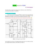
Inverse Time Circuit Breakers
Inverse time circuit breakers have both thermal and instantaneous trip features and are preset to trip
at standardized levels. This is the most common type of circuit breaker used in the building trades
for residential, commercial, and heavy construction.
C The thermal action of this circuit breaker responds to
heat.
C If a motor’s ventilation inlets and outlets are not
adequate to dissipate heat from the windings of the
motor, the heat will be detected by the thermal action
of the circuit breaker.
• If a short should occur, the magnetic action of the
circuit breaker will detect the instantaneous values of
current and trip the circuit breaker.
• The National Electrical Code requires inverse time
circuit breakers to be sized to a maximum of 250%
of the motor FLA.
Inverse Time Circuit Breaker Trip Settings
Size
(Amps)
Voltage Percent of
Load Held
Time
(seconds)
100 or less 240 300% 4
100 or less 480 300% 9
110-225 240/480 300% 35
400-500 240/480 300% 50
600 or more 240/480 300% 40
The rating of an inverse time circuit
breaker can be multiplied by 3 and
this total amperage will start any
motor with less locked-rotor
amperage.
The time it takes to reach the 300%
level varies with the amperage and
voltage ratings of the breaker as
shown in the table.
14
0.01
0.1
1
10
Time (seconds)
0
500
1000
1500
2000
Amp Rating (%)
Instantaneous Trip CB
10 X Rating
3 X Rating
Instantaneous Trip Circuit Breakers
Instantaneous trip circuit breakers respond to immediate (almost instantaneous) values of current
from a short circuit, ground fault, or locked rotor current.
C This type of circuit breaker will
never trip from a slow heat
buildup due to motor windings
overheating.
• A stuck bearing or a blanket of
lint covering the inlets and outlets
of the motor’s enclosure will
cause the motor to overheat and
damage the windings.
• The National Electrical Code
allows instantaneous trip circuit
breakers to be sized to a
maximum of 800% of a motors FLA value.
• They are used where time-delay fuses set at five times their ratings or circuit breakers at
three times their rating will not hold the starting current of a motor.
Some instantaneous trip circuit breakers have adjustable trip settings. The instantaneous trip ratings
of an instantaneous trip circuit breaker can be adjusted above the locked-rotor current of a motor to
allow the motor to start and come up to its running speed.
Example: an instantaneous trip
circuit breaker can be set at 700
amps to permit a motor with a
locked-rotor current of 650
amps to start.
• Care must be exercised
not to adjust the trip
setting above 800%
unless specifically
required. The NEC
15
prohibits settings above
800% if the motor will
start and run up to speed
at or below a setting of
800%.
16
Motor Overload Protection
Motors larger than 1 horsepower must be provided separate motor overload protection devices.
C The most common devices typically used include:
1) magnetic or thermal overload devices
2) electronic overload relays
3) fuses
Magnetic & Thermal Overloads
Overload devices are usually located in the motor’s starter and connected in series with the motors
electrical supply circuit and can be operated by either magnetic or thermal action.
C The same amount of current passes through the overload relay and the motor.
C If the current or heat through the overload device is higher than the device’s rating, it trips
and shuts down the electric power to the motor.
Magnetic Overload Relays
A magnetic overload relay is an electro-mechanical relay operated by the current flow in a circuit.
C When the level of current in the circuit reaches a preset value, the increased magnetic field
opens a set of contacts.
• Electromagnetic overload relays
operate on the magnetic action
of the load current flowing
through a coil.
C When the load current becomes
too high, a plunger is pulled up
into the coil interrupting the
circuit.
C The tripping current is adjusted by altering the initial position of the plunger with respect to
the coil.
17
Thermal Overload Relays
A thermal overload relay is an electro-mechanical relay that is operated by heat developed in the
relay.
C When the level of current in a circuit reaches a preset value, the increased temperature opens
a set of contacts.
C The increased temperature opens the contacts through a bimetallic strip or by melting an
alloy that activates a mechanism that opens the contacts.
C Two types include melting alloy and the bi-metallic strip.
Melting-Alloy Thermal Overload Relays:
These are probably the most popular type of overload protection.
C The motor current passes through a small
heater winding and under overload
conditions, the heat causes a special solder to
melt allowing a ratchet wheel to spin thus
opening the control circuit contacts.
C Must be reset by hand operation
C Heater coil and solder pot in one unit —
non-tamperable
Bimetallic Thermal Overload Relays:
This design uses a bimetal strip associated with a current-carrying heater coil.
C When an overload occurs,
the heat causes the bimetal to
deflect and actuate a tripping
mechanism which opens a set
of contacts in the control
circuit interrupting power to
the coil and opening the
power contacts.
C Most relays are adjustable
over a range from 85% to 115% of their value.
C They are available with ambient compensation. An ambient compensated devices’ trip point
is not affected by ambient temperature and performs consistently at the same value of
current.
18
Automatic Reset Devices
Automatic reset is an advantage where the starter is inaccessible and the motor is provided three
wire control from a magnetic
starter.
C This control doesn’t allow
the motor to restart until
the start push button is
manually pushed.
C This permits the overload
condition to be removed
before the motor restarts.
Electronic Overloads
Electronic overloads sense the load current and the heating effect on the motor is computed. If an
overload condition exists, the sensing circuit interrupts the power circuit.
C The tripping current can be adjusted to suit the particular application.
C Electronic overloads often perform additional protective functions such as ground fault and
phase loss protection.
Fuses
Fuses have limited application as the primary means of overload protection for motors but can be
effectively used to provide back up overload protection.
• Single-element fuses are not designed to provide overload protection.
C Their basic function is to protect against short circuits and ground faults.
C If sized to provide overload protection, they would blow when the motor starts due to high
motor inrush current.
• Dual-element fuses can provide motor overload protection, but they have to be replaced
when they blow which can be a disadvantage.
• There is a risk of single-phasing damage to the motor when only one fuse blows unless
single-phase protection is provided.
19
1
10
100
1000
Trip Time (Seconds)
0
200
400
600
800
1000
1200
Rated Current (%)
Heater Trip Characteristics
Overload Trip Time
The time it takes an overload to trip depends on the length of time the overload current exists.
• A Heater Trip
Characteristics chart shows
the relationship between the
time an overload takes to
trip and the current flowing
in the circuit based on the
standard 40EC ambient
temperature installation.
• The larger the overload
(horizontal axis), the shorter
the time required to trip the
overload (vertical axis).
• Any change from ambient
temperature affects the tripping time of an overload.
S For temperatures higher than 40EC, the overloads trip at a current rating less than the
value of the overload.
• Example: At 50EC the overloads trip at 90% of their rated value. For temperatures lower
than 40EC, the overloads trip at a current rating greater than the rated value of the overload.
20
Sizing Motor Overload Protection
There are several types of devices that can be used to provide overload protection and the sizing
procedure can vary depending on the type of device used.
C It is important to keep differences in the procedures separate and understood well so as not to
install overloads that do not provide adequate protection to the motor.
• The simplest and most straightforward sizing procedures for motor overload protection are
applied when sizing overload relays using the cover of the motor starter, control center, or
manufacturer’s catalog.
• The National Electrical Code specifies methods to calculate the maximum size motor
overload protection for specific motors if a manufacturers chart is not available. Installations
relying on fuses and circuit breakers as back-up overload protection must be calculated using
the NEC method.
NEC Calculations
The NEC in general requires the maximum size overload device be set to open at 115% or 125% of
the motor’s full-load current rating, depending upon the service factor and/or temperature rise of the
motor. There are however, exceptions.
• For motors rated 40EC with a Service Factor of 1.15 or greater, 125% of the motors FLA is
used to calculate the maximum size device for overload protection.
• For motors rated greater than 40EC or unmarked, 115% of the motors FLA is used to
calculate the maximum size device regardless of the motor’s Service Factor.
• If use of the previous size rules results in the motor tripping off line during starting, the
device can be increased to a maximum of 140% of the motors FLA.
Example:
Find the maximum size overload device to provide overload protection to a 3 phase, 230 Volt, 10
horsepower motor with FLA of 28 amps if:
Ambient Temp = 40EC, S.F.=1.15: 28 amps X 125% = 35 amps
Ambient Temp = 40EC, S.F.=1.00: 28 amps X 115% = 32.2 amps
Ambient Temp = 50EC, S.F.=1.15 28 amps X 115% = 32.2 amps
Ambient Temp = 50EC, S.F.=1.00 28 amps X 115% = 32.2 amps
If use of the size calculated results in the motor tripping off line when started, the overload device
may be increased to a maximum of:
Maximum size allowable: 28 amps X 140% = 39.2 amps
Selecting Overloads From Starter Covers or Charts
21
The size overloads required to protect the windings of a motor can be determined by taking the
motor’s full-load current rating and selecting the size overloads from the cover of a magnetic starter,
a motor control center, or the manufacturer’s catalog.
C The following things should be kept in mind when using manufacturer’s charts.
• When the overload size is selected from the cover of a magnetic starter or controller, the
nameplate full-load running current of the motor is used. The full-load running current is
NOT
increased by 125% when the overloads are selected in this manner.
• The charts are usually based on only the specific manufacturer’s equipment.
• Sizes from the charts may be different from those of calculated values from the National
Electrical Code.
C Manufacturers charts often provide smaller rated devices than the NEC would allow as a
measure of extra protection.
• Manufacturers’ typically list the most common sizes in their charts. Certain sizes may
require calculations if the chart is not available from the manufacturer.
• If the motor will operate at/near service factor, the appropriate FLA of the motor at its
Service Factor should be used to select the overload size from the manufacturer’s chart.
OVERLOAD CHART
AMPERAGE OVERLOAD UNIT
20.6-23.3
23.4-26.0
26.1-30.5
H1042
H1043
H1044
30.6-33.6
33.7-37.9
38.0-42.9
43.0-48.2
48.3-54.6
H1045
H1046
H1047
H1048
H1049
54.7-61.2
61.3-67.6
67.7-75.9
76.0-87.1
87.2-97.5
H1050
H1051
H0152
H1054
H1055
97.6-109.0
110.0-112.0
123.0-135.0
H1056
H1057
H1058
Example:
A three-phase motor with a full-load current
rating of 39 amps and a Service Factor of 1.00
requires three overload units with catalog number
H1047.
Overload units number H1047 are selected
because the 39-amp full-load current rating of the
motor is between 38.0 and 42.9 amps.
What if the previous motor had a 1.15 Service
Factor?
39 amps X 1.15 = 44.85 amps
The motor requires three overload units with
catalog number H1048 because the 44.85 amps
of the motor at Service Factor is between 43.0
and 48.2 amps.
22
60
70
80
90
100
110
120
130
140
Rated Current (%)
20
40
60
80
100
120
140
160
Ambient Temperature (F)
Heater Ambient Temperature Correction
Standard Rating, 40 C
60
70
80
90
100
110
120
130
140
Rated Current (%)
20
40
60
80
100
120
140
160
Ambient Temperature (F)
Ambient Temperature Correction
Standard Rating, 40 C
Non-Compensated
Compensated
Ambient Temperature Compensation
The ambient temperature in which a starter and motor is located must be considered when selecting
overloads because a high ambient temperature reduces overload trip time.
C Reduced overload trip time can lead to nuisance tripping if a motor is located in a cooler
ambient temperature than the starter and lead to motor burnout when the motor is located in a
hotter ambient temperature than the starter.
• Most thermal overload devices are rated
for use at a maximum temperature of 40
degrees C which is about 104 degrees F.
• The overload device trips at less than
100 percent rated current when the
ambient temperature exceeds 104
degrees F which can result in “nuisance
tripping”.
If the temperature is significantly below 104
degrees F, the overload device allows significantly more current through than it is rated for resulting
in potential motor overload and failure without the overload tripping the motor off.
• A higher overload heater can be selected when the ambient temperature at the starter is
higher than the temperature at the motor and a lower value selected when the ambient
temperature at the starter is lower than the temperature at the motor.
• If the temperature varies widely during the year, the motor may not be protected when the
temperature swings dramatically the other way unless the original overloads are switched
back.
Ambient Compensated Heaters
For this reason, special Ambient
Compensated Heaters which
have a much “flatter”
temperature response should be
used in most outdoor
applications and where ambient
operating temperatures are
significantly different.
23
Sizing Motor Protection Systems
Given the following motor, size the conductors, motor overcurrent and motor overloads to
adequately protect the motor and conductors.
Nameplate Info: FLA = 22 Service Factor = 1.00 Ambient = 40 C
STEP 1: Determine the motor’s FLA (full load amps)
C Go to the appropriate NEC Table to find the design FLA
S NEC Table 430-150 for 3 phase: For 10 Hp, 230 Volt Motor = 28 amps
STEP 2: Determine the size of branch circuit conductor required.
C NEC 430-22 says the conductor ampacity equals the FLA x 125%
S Conductors supplying a single motor used for a continuous duty load must have a current
carrying capacity of not less than 125% of the motor’s full load current (FLA) rating as
given in NEC tables 430-148 or 430-150.
S Conductor Ampacity = 28 amps X 1.25 = 35 amps
C Use NEC Table 310-16 to select the conductor with the required ampacity
S From NEC Table 310-16: #8 AWG Copper
C The NEC procedure requires use of the #8 AWG conductor so it will be large enough for any
motor of the same size in the future.
STEP 3: Determine the branch circuit overcurrent device size.
24
The maximum branch circuit overcurrent device size is calculated based on the type of protective
device selected (standard fuse, time-delay fuse, instantaneous breaker, inverse time breaker) and
percentage multiplier from NEC Table 430-152.
C Multiply the motors design FLA by the appropriate percentage in NEC Table 430-152.
1. When the value found does not match a standard fuse/breaker size the NEC permits the
next higher STANDARD size for a branch circuit overcurrent device.
Standard Fuse
28 X 300% = 84 amps
Next Highest: 90 amps
Time-Delay
Fuse
28 X 175% = 49 amps
Next Highest: 50 amps
Instantaneous
Breaker
28 X 800% = 224 amps
Next Highest: 225 amps
Inverse Time
Delay Breaker
28 X 250% = 70 amps
Next Highest: 80 amps
STEP 4: Determine the required size for the motor running overload protection.
1. Use the nameplate FLA directly to find the appropriate overload device heater on the motor
starter cover or from manufacturers tables.
2. Use the nameplate FLA and NEC Section 430-32 to calculate the maximum size for the
motor overload protection in amps.
C NEC Section 430-32 specifies the maximum overload protection size for most installations if
nameplate amps aren’t available. (FLA X 115% or FLA X 125% depending on criteria).
S Since the motor’s ambient rating was 40 deg C and the S.F. was 1.0, use 115%.
For Ambient of 40 deg C and S.F. = 1.0: 22 amps X 115% = 25.3 amps
C NEC Section 430-34 specifies the maximum size if th calculated value in Section 430-32 will
not allow the motor to start consistently. (Motor FLA X 140%).
22 amps X 140% = 30.8 amps MAXIMUM