Astm e 2188 10
Bạn đang xem bản rút gọn của tài liệu. Xem và tải ngay bản đầy đủ của tài liệu tại đây (105.37 KB, 5 trang )
Designation: E2188 − 10
An American National Standard
Standard Test Method for
Insulating Glass Unit Performance1
This standard is issued under the fixed designation E2188; the number immediately following the designation indicates the year of
original adoption or, in the case of revision, the year of last revision. A number in parentheses indicates the year of last reapproval. A
superscript epsilon (´) indicates an editorial change since the last revision or reapproval.
E631 Terminology of Building Constructions
E546 Test Method for Frost/Dew Point of Sealed Insulating
Glass Units
E2190 Specification for Insulating Glass Unit Performance
and Evaluation
1. Scope
1.1 This test method covers procedures for testing the
performance of preassembled permanently sealed insulating
glass units or insulating glass units with capillary tubes
intentionally left open.
3. Terminology
1.2 This test method is applicable only to sealed insulating
glass units that are constructed with glass.
3.1 Definition of Terms:
3.1.1 For definitions of terms found in this standard, refer to
Terminologies C162, C717, and E631.
1.3 This test method is applicable to both double-glazed and
triple-glazed insulating glass units. For triple-glazed insulating
glass units where both of the outer lites are glass and the inner
lite is either glass or a suspended film.
3.2 Definitions of Terms Specific to This Standard:
3.2.1 frost/dew point, n—the temperature at which water,
organic vapor, or other chemicals begin to appear on the
interior glass surface of a sealed insulating glass unit.
1.4 The unit construction used in this test method contains
dimensions that are an essential component of the test. Different types of glass, different glass thicknesses, and different
airspace sizes may affect the test results.
4. Significance and Use
4.1 This test method is intended to provide a means for
testing the performance of the sealing system and construction
of sealed insulating glass units.
4.1.1 Sealed insulating glass units tested in accordance with
this method may be suitable for structurally glazed applications. However, factors such as sealant longevity when exposed to long term ultraviolet light and the structural properties
of the sealant must be reviewed for these applications.
4.1.2 Sealed insulating glass units tested in accordance with
this method are not intended for continuous exposure to high
relative humidity conditions or long-term immersion in water.
1.5 This test method is not applicable to sealed insulating
glass units containing a spandrel glass coating due to testing
limitations.
1.6 The values stated in SI units are to be regarded as
standard. No other units of measurement are included in this
standard.
1.7 This standard does not purport to address all of the
safety concerns, if any, associated with its use. It is the
responsibility of the user of this standard to establish appropriate safety and health practices and determine the applicability of regulatory limitations prior to use.
5. Test Specimens
2. Referenced Documents
5.1 Each test specimen shall measure 355 6 6 mm by
505 6 6 mm and shall be composed of two or three lites of
clear, tinted or coated annealed, heat-strengthened, tempered,
or laminated glass.
5.1.1 The double-glazed test samples shall be fabricated
with at least one lite of clear, uncoated glass. The triple-glazed
test samples shall be fabricated with at least one outer lite of
clear, uncoated glass. The other outer lite shall be fabricated
with a glass which allows easy viewing of the frost point.
5.1.2 The thickness of the glass lites shall be between
nominal 3.0 mm and a maximum of 6.0 mm nominal.
5.1.3 The airspaces for units with either two or three lites of
glass shall be a minimum of 6.0 6 0.8 mm.
5.1.4 When testing to Specification E2190 the specimen
construction shall be as defined in that document.
2.1 ASTM Standards:2
C162 Terminology of Glass and Glass Products
C717 Terminology of Building Seals and Sealants
C1036 Specification for Flat Glass
1
This test method is under the jurisdiction of ASTM Committee E06 on
Performance of Buildings and is the direct responsibility of Subcommittee E06.22
on Durability Performance of Building Constructions.
Current edition approved Nov. 1, 2010. Published February 2011. Originally
approved in 2002. Last previous edition approved in 2002 as E2188 – 02. DOI:
10.1520/E2188-10.
2
For referenced ASTM standards, visit the ASTM website, www.astm.org, or
contact ASTM Customer Service at For Annual Book of ASTM
Standards volume information, refer to the standard’s Document Summary page on
the ASTM website.
Copyright © ASTM International, 100 Barr Harbor Drive, PO Box C700, West Conshohocken, PA 19428-2959. United States
1
E2188 − 10
5.1.5 Triple-pane units where the intermediate airspace
divider is a plastic film are acceptable.
testing as long as they have been manufactured with the same
techniques as used in production.
NOTE 1—Overall unit thickness has some limits. Testing laboratories
are usually able to accommodate 30 mm overall thickness. If testing
thicker units, contact the testing laboratory prior to manufacturing to
ascertain their capabilities for testing thicker units.
5.8 Test specimens representing insulating glass units that
include tubes intended to be left open shall be fabricated with
one tube. These tubes shall be left open during testing. Test
samples representing units that include tubes intended to be
closed off after shipping shall be fabricated with one tube.
These tubes shall be closed at the exterior end prior to testing.
5.2 The thickness tolerance of the glass shall conform to
Specification C1036.
5.3 Each specimen shall be permanently and legibly marked
with the designation of the manufacturer, the date of fabrication (month or quarter and year) and orientation intended in the
field (for units constructed with coated glass).
6. Apparatus
6.1 For Weather Cycle Phase:
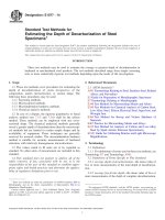
6.1.1 Weather Cycle Test Apparatus3—The weather cycle
test apparatus shall be essentially that shown in Figs. 1 and 2
to provide the required test conditions indicated in Section 8.
Modifications to this test apparatus are acceptable providing
that the required test conditions are met.
6.1.1.1 Ultraviolet Light Source —(Warning—Ultraviolet
light sources used in this test method are harmful, especially to
the eyes. Appropriate protective measures must be observed.)
6.1.1.2 The source shall consist of two fluorescent ultraviolet lamps, Type F72T12BL/HO4 (Note 2), for each test
specimen located as shown in Fig. 1.
5.4 At least nine specimens of identical component materials and construction shall be submitted for testing.
5.5 During all stages of exposure and storage, the units shall
be held in a vertical position with equal support to all panes and
no compression loading.
5.6 Selection of six specimens for testing shall be made at
random from the submitted specimens except for specimens
damaged in transit. Damaged specimens shall not be tested.
5.7 Test specimens representing insulating glass units that
will be gas filled shall be fabricated using the same hole sealing
and gas filling techniques as those used for manufacturing. For
example, if a gas-filling plug is used in manufacturing then it
must be used in the test units. The samples do not need to be
filled with gas providing that the gas is classified as inert. Test
samples representing products that are normally filled with an
inert gas in production, may be submitted air filled for this
3
The apparatus is a modification of the device developed by the Institute for
Research in Construction (IRC) of the National Research Council of Canada. One
modification was to expose each test specimen to two ultraviolet lamps.
4
Available from General Electric Company (GE), Nela Park, Cleveland, OH
44112, .
Description: (1) Fog or mist spray; (2) Cooling coil; (3) Fluorescent ultraviolet lamp, F72T12BL/HO; (4) Heating coil; (5) Rubber pad; (6) Polystyrene insulation; (7) Rubber
washer; (8) Clamping device; (9) Test specimen; (10) Fan motor; (11) Air duct; (12) Insulation
FIG. 1 Schematic Drawing of Typical Accelerated Weathering Apparatus
2
E2188 − 10
FIG. 2 Location of Fluorescent Ultraviolet Lamp Relative to the Test Specimen
glass surface for detection of frost. For example, place a mask
of plastic tape6 50 by 50 mm or larger, on the central region of
both exterior glass surfaces before exposing the unit to
weathering conditions. Remove the mask for frost/dew point
measurement.
NOTE 2—Rated average life at 3 h per start: 12 000 h. Rated average life
at 12 h per start: 18 000 h. Useful length: 1625 mm. Wattage: 85 W.
Relative ultraviolet energy output is 190 % that of F40BL lamp (not high
output), when measured at 340 nm.
6.1.1.3 Each lamp shall be replaced when its ultraviolet
light intensity falls below 10 W/m2 (1000 µW/cm2) when
measured with a long-wave ultraviolet meter5 in direct contact
with the lamp.
6.1.2 Protect the accelerated weathering chamber from
overheating and from overcooling with protective devices.
6.1.3 Equip the accelerated weather cycle chamber with one
or more sensors and a continuous temperature recording device
placed in an area that measures the representative air temperature at any time inside the chamber.
7.2 The sealed insulating glass units shall be sealed a
minimum of 4 weeks from date of manufacture to allow for
stabilization before testing. The manufacturer shall be permitted to waive this requirement.
8. Procedure for Seal Durability
8.1 Initial Frost/Dew Point Test:
8.1.1 Determine the initial frost/dew point on all airspaces
on all units submitted using Test Method E546 or equivalent.
6.2 For High Humidity Phase:
6.2.1 High Humidity Test Chamber—A chamber of convenient dimensions capable of maintaining 60 6 3°C and
95 6 5 % relative humidity.
6.2.2 The high humidity chamber shall be protected from
overheating with a protective device.
6.2.3 Equip high humidity chamber with one or more
sensors and a continuous air temperature-recording device
placed in an area that monitors the average temperature in the
chamber.
8.2 High Humidity Phase:
8.2.1 Place the test specimens that were tested in accordance
with 8.1 in the high humidity test apparatus. Expose six
specimens in the high-humidity test chamber at 60 6 3°C and
95 6 5 % relative humidity. Arrange the specimens so that
each specimen has at least 6 mm clearance all around.
8.2.2 When the specified time period (days) has been
attained,7 remove the test specimens. Allow the test specimens
to equilibrate at 23 6 3°C for not less than 24 h. Determine the
frost/dew point in accordance with Test Method E546 or
equivalent. For triple-pane units, the frost/dew point shall be
determined for all airspaces. If liquid appears, record the
temperature at which it occurs.
7. Preparation of Test Specimens
7.1 Uncleanable stain or scum may remain on the exterior
glass surface of the specimen after the accelerated weathering
test. Measures shall be taken to have a clear view of the interior
5
The only suitable meter is the Blak-Ray UV Meter with J221 sensor cell. The
sole source of supply of the apparatus known to the committee at this time is UVP,
LLC, 2066 West 11th Street, Upland, CA 91786. If you are aware of alternative
suppliers, please provide this information to ASTM International Headquarters.
Your comments will receive careful consideration at a meeting of the responsible
technical committee,1 which you may attend.
6
Scotch Plastic Tape #471 available from 3M Company, 3M Center, Commercial
Office Supply Division, Bldg. 230-3 South-17, St. Paul, MN 55101, has been found
suitable for this purpose.
7
The amount of time under the high humidity test condition is optional and is at
the discretion of the test specifier. When testing to Specification E2190, the amount
of time required is specified in that document.
3
E2188 − 10
8.3.3.8 When the specified number of cycles has been
attained,8 remove the test specimens. Allow the test specimens
to equilibrate at 23 6 3°C for not less than 24 h. Determine the
frost/dew point in accordance with Test Method E546 or
equivalent. For triple-pane units, the frost/dew point shall be
determined for all airspaces. If liquid appears, record the
occurrence.
8.3 Weather Cycle Phase:
8.3.1 Place the six test specimens tested in accordance with
8.1 and 8.2 in the weather cycle chamber. Mount the specimens
so that one exterior surface of the specimen is exposed to the
weather cycles and the other to room temperature (23 6 3°C).
Install all specimens as shown in Fig. 1, taking care that no
stress is induced in the test specimens by the method of
fastening.
8.3.2 The test specimens shall be oriented in the weather
cycle chamber with the number one surface facing the weather
changes as it does in normal field exposure.
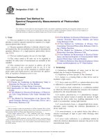
8.3.3 Cycling—Each cycle shall be 6 h 6 5 min and composed of the following test conditions (see Fig. 3):
8.3.3.1 During the first 60 6 5 min, decrease the air temperature from room temperature to −29 6 3°C.
8.3.3.2 Maintain air temperature at −29 6 3°C for
1 h 6 5 min.
8.3.3.3 Control the air temperature rise from –29 6 3°C to
room temperature over a period of 60 6 5 min. Use the heat
source as needed.
8.3.3.4 Start the ultraviolet lamps and over a time period of
60 6 5 min control the temperature rise from room temperature to 60 6 3°C. At the beginning of this same 60 min period,
turn on water or mist supply. The interior of the chamber, at the
test specimens, shall achieve a minimum of 90 % relative
humidity (RH) within this time period. It is not necessary to
stay at or above 90 % RH as long as the environment achieves
90 % RH sometime in this 60 min time.
8.3.3.5 Turn off the water or mist supply after 60 min.
8.3.3.6 Maintain temperature at 60 6 3°C and continue
ultraviolet exposure for a period of 60 6 5 min.
8.3.3.7 Over a period of 60 6 5 min, decrease temperature
from 60 6 3°C to room temperature, and continue ultraviolet
exposure. At the end of this period, turn off ultraviolet lamp.
9. Measurements and Observations
9.1 Observe the following:
9.1.1 Glass breakage.
9.1.2 Any visible deposit in the airspace.
9.2 Measure the following:
9.2.1 Measure the frost/dew point of each insulating glass
unit.
10. Report
10.1 Complete Description of Specimen Tested:
10.1.1 Dimensions of the test specimen (width by height)
and overall thickness.
10.1.2 Type and thickness of glass.
10.1.3 Glass coatings and surface locations if applicable.
10.1.4 Airspace thickness(es).
10.1.5 Spacer composition(s) and configuration(s).
10.1.6 Corner construction.
10.1.7 Type and number of spacer connecting methods/
components.
10.1.8 Desiccant type and quantity, if provided.
10.1.9 Presence and type of tube, if applicable.
8
The number of cycles is optional and is at the discretion of the test specifier.
When testing to Specification E2190, the number of cycles is specified in that
document.
NOTE 1—This figure represents the ideal cycle described in this test method. Any temperature variation within the tolerance zone shown is acceptable.
FIG. 3 Schematic Drawing of Each Cycle for Accelerated Weather Cycle Test
4
E2188 − 10
10.1.10
10.1.11
10.1.12
quarter, if
10.4 Frost/dew point of each unit after testing to 8.1-8.3, if
observed.
Presence and type of gas fill plug, if applicable.
Sealant type(s) and dimensions, if provided.
Manufacturer and manufactured date (month or
known, and year).
10.5 Any visible deposit(s) in the airspace.
11. Precision and Bias
10.2 Duration of Test:
10.2.1 Duration of high humidity phase described in 8.2
(number of days).
10.2.2 Duration of accelerated weather cycle phase described in 8.3 (number of cycles).
10.2.3 Duration of any additional testing including type and
order of testing and number of cycles or days.
11.1 Precision and Bias—The precision and bias of this test
method for measuring the frost/dew point of insulating glass
durability performance are essentially as specified in Test
Method E546.
12. Keywords
12.1 IGU performance; IGU seal durability; insulating glass
units (IGU); sealed insulating glass units
10.3 Glass breakage, if observed.
ASTM International takes no position respecting the validity of any patent rights asserted in connection with any item mentioned
in this standard. Users of this standard are expressly advised that determination of the validity of any such patent rights, and the risk
of infringement of such rights, are entirely their own responsibility.
This standard is subject to revision at any time by the responsible technical committee and must be reviewed every five years and
if not revised, either reapproved or withdrawn. Your comments are invited either for revision of this standard or for additional standards
and should be addressed to ASTM International Headquarters. Your comments will receive careful consideration at a meeting of the
responsible technical committee, which you may attend. If you feel that your comments have not received a fair hearing you should
make your views known to the ASTM Committee on Standards, at the address shown below.
This standard is copyrighted by ASTM International, 100 Barr Harbor Drive, PO Box C700, West Conshohocken, PA 19428-2959,
United States. Individual reprints (single or multiple copies) of this standard may be obtained by contacting ASTM at the above
address or at 610-832-9585 (phone), 610-832-9555 (fax), or (e-mail); or through the ASTM website
(www.astm.org). Permission rights to photocopy the standard may also be secured from the ASTM website (www.astm.org/
COPYRIGHT/).
5