Astm f 390 11
Bạn đang xem bản rút gọn của tài liệu. Xem và tải ngay bản đầy đủ của tài liệu tại đây (89.43 KB, 4 trang )
Designation: F390 − 11
Standard Test Method for
Sheet Resistance of Thin Metallic Films With a Collinear
Four-Probe Array1
This standard is issued under the fixed designation F390; the number immediately following the designation indicates the year of original
adoption or, in the case of revision, the year of last revision. A number in parentheses indicates the year of last reapproval. A superscript
epsilon (´) indicates an editorial change since the last revision or reapproval.
3.1.1 thin film—a film having a thickness much smaller than
any lateral dimension, formed by deposition of a material or by
a thinning process.
3.1.2 thin metallic film—a thin film composed of a material
or materials with resistivity in the range from 10 −8 to 10−3
Ω·cm.
1. Scope
1.1 This test method covers the measurement of the sheet
resistance of metallic thin films with a collinear four-probe
array. It is intended for use with rectangular metallic films
between 0.01 and 100 µm thick, formed by deposition of a
material or by a thinning process and supported by an
insulating substrate, in the sheet resistance range from 10−2 to
10 4 Ω/□ (see 3.1.3).
3.1.3 sheet resistance, Rs[Ω/□]— in a thin film, the ratio of
the potential gradient parallel to the current to the product of
the current density and the film thickness; in a rectangular thin
film, the quotient of the resistance, measured along the length
of the film, divided by the length, l, to width, w, ratio. The ratio
l/w is the number of squares.
1.2 This test method is suitable for referee measurement
purposes as well as for routine acceptance measurements.
1.3 The values stated in SI units are to be regarded as the
standard. The values given in parentheses are for information
only.
1.4 This standard does not purport to address the safety
concerns, if any, associated with its use. It is the responsibility
of whoever uses this standard to consult and establish appropriate safety and health practices and determine the applicability of regulatory limitations prior to use.
4. Summary of Test Method
4.1 A collinear four-probe array is used to determine the
sheet resistance by passing a measured direct current through
the specimen between the outer probes and measuring the
resulting potential difference between the inner probes. The
sheet resistance is calculated from the measured current and
potential values using correction factors associated with the
geometry of the specimen and the probe spacing.
2. Referenced Documents
2.1 ASTM Standards:2
E2251 Specification for Liquid-in-Glass ASTM Thermometers with Low-Hazard Precision Liquids
F388 Method for Measurement of Oxide Thickness on
Silicon Wafers and Metallization Thickness by MultipleBeam Interference (Tolansky Method) (Withdrawn 1993)3
4.2 This test method includes procedures for checking both
the probe assembly and the electrical measuring apparatus.
4.2.1 The spacings between the four probe tips are determined from measurements of indentations made by the tips in
a suitable surface. This test also is used to determine the
condition of the tips.
4.2.2 The accuracy of the electrical measuring equipment is
tested by means of an analog circuit containing a known
standard resistor together with other resistors which simulate
the resistance at the contacts between the probe tips and the
film surface.
3. Terminology
3.1 Definitions:
1
This test method is under the jurisdiction of ASTM Committee F01 on
Electronics and is the direct responsibility of Subcommittee F01.17 on Sputter
Metallization.
Current edition approved June 1, 2011. Published July 2011. Originally approved
in 1973 as F390 – 73 T. Last previous edition approved in 2003 as F390 – 98(2003).
DOI: 10.1520/F0390-11.
2
For referenced ASTM standards, visit the ASTM website, www.astm.org, or
contact ASTM Customer Service at For Annual Book of ASTM
Standards volume information, refer to the standard’s Document Summary page on
the ASTM website.
3
Withdrawn. THe last approved version of this historical standard is referenced
on www.astm.org.
5. Apparatus
5.1 Probe Assembly:
5.1.1 Probes—The probe shaft and tip shall be constructed
of tungsten carbide, Monel, hardened tool steel, or hard copper
and have a conical tip with included angle of 45 to 90°.
Alternatively, the tip may be formed from a platinumpalladium alloy and resistance welded to the shaft. The tip shall
have a nominal initial radius of 25 to 50 àm. In all cases all of
Copyright â ASTM International, 100 Barr Harbor Drive, PO Box C700, West Conshohocken, PA 19428-2959. United States
1
F390 − 11
process, with no further cleaning or preparation. The test
specimen shall be supported by a substrate consisting of a
suitable insulating material.
the four paths from the electrical measurement equipment
inputs to the film surface must be identical.
5.1.2 Probe Force—The probes shall be uniformly loaded to
exert a force sufficient to deform the metal film but insufficient
to puncture the film. A rough guide for loading is a load of 20
g/Mohs (unit of hardness) of the film material on each probe.
5.1.3 Probe Characteristics—The probes shall be mounted
in an insulating fixture such as a sapphire bearing in a methyl
methacrylate or hardened polystyrene block in an equally
spaced linear array. The electrical insulation between adjacent
probe points shall be at least 105 times greater than the V/I ratio
of the film. The spacing shall be 0.64 to 1.00 mm inclusive
(0.025 to 0.040 in. inclusive) as agreed upon between the
parties concerned with the test. The precision and reproducibility of the probe spacing shall be established according to the
procedure of 7.1.
5.1.4 Probe Support—The probe support shall allow the
probes to be lowered perpendicularly onto the surface of the
specimen so that the center of the array is centered on the
specimen within 610 % of the specimen length l and width w.
6.2 Geometry—Measure the length, l, and width, w, of the
specimen with vernier calipers. Record the values.
6.3 Measure the thickness, t, of the film in accordance with
Method F388.
7. Suitability of Test Equipment
7.1 Probe Assembly—The probe spacing and tip condition
shall be established in the following manner. It is recommended that this be done immediately prior to a referee
measurement.
7.1.1 Procedure:
7.1.1.1 Make a series of indentations on the surface of the
specimen to be tested or other surface of similar hardness with
the four-probe array. Make these indentations by applying the
probes to the surface using normal point pressures. Lift the
probes and move either the specimen surface or the probes 0.05
to 0.10 mm in a direction perpendicular to a line through the
probe tips. Again apply the probes to the specimen surface.
Repeat the procedure until a series of ten indentation sets is
obtained.
5.2 Electrical Measuring Apparatus:
5.2.1 The electrical apparatus shall consist of a suitable
voltmeter, current source, ammeter, and electrical connections
(see 7.2).
5.2.2 Voltmeter with input impedance 104 times the V/I ratio
of the film. A vacuum-tube voltmeter, a digital voltmeter, or
similar high-impedance input apparatus is suitable.
5.2.3 Current Source with current regulation and stability of
60.1 % or better. The recommended current range is from 0.01
to 100 mA.
5.2.4 Ammeter capable of reading direct current in the range
from 0.01 to 100 mA to an accuracy of 60.1 % or better.
5.2.5 The current source and ammeter are connected to the
outer probes; the voltmeter is connected to the inner probes.
NOTE 1—It is recommended that the surface or the probes be moved
twice the usual distance after every second or every third indentation set
in order to assist the operator in identifying the indentations belonging to
each set.
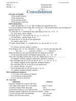
7.1.1.2 Place the specimen so indented on the stage of the
toolmaker’s microscope so that the Y-axis readings (YA and YB
in Fig. 1) do not differ by more than 0.15 mm (0.006 in.). For
each of the ten indentation sets record the readings A through
H (defined in Fig. 1) on the X-axis of the toolmaker’s
microscope and the readings YA and YB on the Y-axis.
7.1.2 Calculations:
7.1.2.1 For each of the ten sets of measurements calculate
the probe separations, S1j, S2j, and S3j from the equations:
S 1j 5 @ ~ C j 1D j ! /2 # 2 @ ~ A j 1B j ! /2 # ,
5.3 Specimen Support—A copper block at least 100 mm
(approximately 4 in.) in lateral dimensions and at least 40 mm
(approximately 1.5 in.) thick, shall be used to support the
specimen and provide a heat sink. It shall contain a hole that
will accommodate a thermometer (see 5.4) in such a manner
that the center of the bulb of the thermometer shall be not more
than 10 mm below the central area of the top of the block
where the specimen is to be placed.
S 2j 5 @ ~ E j 1F j ! /2 # 2 @ ~ C j 1D j ! /2 # , and
S 3j 5 @ ~ G j 1H j ! /2 # 2 @ ~ E j 1F j ! /2 #
where the index j is the set number and has a value from 1
to 10.
7.1.2.2 Calculate the average value for each of the three
separations using the Sij calculated above and the equation:
5.4 Thermometer having a range from − 8 to 32°C and
conforming to the requirements for Thermometer 63C as
prescribed in Specification E2251.
S¯ i 5
5.5 Vernier Calipers.
S D(
1
10
10
j51
5 S ij
5.6 Toolmaker’s Microscope capable of measuring increments of 2.5 µm.
6. Test Specimen
6.1 The specimen shall consist of a continuous rectangular
thin metallic film with a thickness greater than 0.01 µm and
less than 100 µm. Thickness variation shall be less than 610 %
of the nominal thickness for thickness from 0.01 µm to 0.1 µm,
inclusive; for greater thicknesses, the variation shall be less
than 65 % of the nominal thickness. The specimen shall be
used as prepared by deposition of a material or by a thinning
FIG. 1 Measurement Locations for Typical Probe Indentation
Pattern
2
F390 − 11
8.4 Place the test specimen on the mounting block under the
probe with the length parallel to the line of the probe array to
within6 2°. Lower the probe onto the test specimen ensuring
that the center of the probe array is centered on the specimen
within 610 % of the specimen length l and width w. Establish
a current (see 8.5.1) between the outer probes. Record the
voltage and current. Perform ten times.
where the index i successively takes the values 1, 2, and 3
(see 7.1.2.1).
7.1.2.3 Calculate the sample standard deviation si for each
of the three separations using theS¯i calculated in 7.1.2.2, the Sij
calculated in 7.1.2.1, and the equation:
si 5
S D F( ~
10
1
3
j51
S ij 2 S¯ i ! 2
G
½
8.5 Caution—Spurious and inaccurate results can arise from
a number of sources.
8.5.1 It is recommended that, consistent with the desired
accuracy, the applied current be as low as possible to reduce
specimen heating. In high resistance or very thin films, it may
be desirable to reduce the specimen current to prevent resistance heating. A drifting of the voltage reading may indicate a
change in the resistance due to heating.
8.5.2 Wear and deformation of the tips in use may make
frequent inspection and replacement necessary.
8.5.3 Spurious currents can be introduced into the test
specimen by high-frequency generators. If equipment is used
near such sources, adequate shielding should be provided.
7.1.2.4 Calculate the average probe spacing S¯ as follows:
S D~
1
S¯ 5
3
S¯ 1 1S¯ 2 1S¯ 3 !
7.1.2.5 Calculate the probe spacing correction factor Fsp as
follows:
F sp 5 111.082@ 1 2 ~ S¯ 2 /S¯ ! #
7.1.3 Requirements—For the probe assembly to be acceptable it must meet the following requirements:
7.1.3.1 Each of the three sets of ten measurements for Si
shall have a sample standard deviation si of less than 1 % of S¯i.
7.1.3.2 The average values of the separations (S¯1, S¯2, and S¯3)
shall not differ by more than 5 % of S¯.
7.1.3.3 The probe indentations shall not puncture the film.
9. Calculations
7.2 Electrical Equipment—The suitability and accuracy of
the electrical equipment shall be established in the following
manner. It is recommended that this be done immediately prior
to a referee measurement.
7.2.1 Measure the current through and voltage across a
standard resistor whose resistance value is within a factor of
ten of the V/I ratio of the film to be measured. Perform ten
times.
7.2.2 Calculate the resistance ri for the ratio of voltage to
current for each measurement.
7.2.2.1 Calculate the average resistance r¯ as follows:
S D(
1
r¯ 5
10
10
j51
9.1 Calculate the specimen resistance Ri from the ratio of
measured voltage and current.
9.2 Calculate the average specimen resistance R¯ as follows:
R¯ 5
s5
1
3
10
j51
10
j51
R¯ i
S D @(
1
3
10
j51
~R
i
2 R¯ !
2
#
½
9.3.1 Requirement—For acceptance of the resistance, the
sample standard deviation s shall be less than 1 % of R¯.
ri
9.4 Calculate the ratio of the specimen width w (see 6.2) to
the average probe separation S¯ (see 7.1.2.4). Calculate the ratio
of specimen length l to specimen width w. Determine the lateral
correction factor c from Table 1 by means of linear interpolation.
7.2.2.2 Calculate the sample standard deviation as follows:
S D @(
1
10
9.3 Calculate the sample standard deviation as follows:
where:
ri = one of the ten values of resistance determined in 7.2.1.
sr 5
S D(
~ r i 2 r¯ ! 2 # ½
7.2.3 Requirements—For the electrical measuring equipment to be suitable, it must meet the following requirements:
7.2.3.1 The value of r¯ must be within 1.0 % of the known
value of r.
7.2.3.2 The sample standard deviation sr must be less than
1.0 % of r¯.
7.2.3.3 The resolution of the equipment must be such that
differences in resistance of 0.05 % can be detected.
TABLE 1 Lateral Correction Factor, c, for Rectangular Thin Films
8. Procedure
8.1 Connect the voltage measuring apparatus to the two
center probes.
8.2 Connect the current source to the outer two probes.
8.3 Equilibrate the specimen at room temperature (236
2°C) on the heat-sink block. Record the temperature.
3
w/ S¯
! /w = 1
! /w = 2
! /w = 3
! /w = 4
1.00
1.25
1.50
1.75
2.00
2.50
3.00
4.00
5.00
7.50
10.00
15.00
20.00
40.00
`
...
...
...
...
...
...
2.4575
3.1137
3.5098
4.0095
4.2209
4.3882
4.4516
4.5190
4.5324
...
...
1.4788
1.7196
1.9454
2.3532
2.7000
3.2246
3.5749
4.0361
4.2357
4.3947
4.4553
4.5129
4.5324
0.9988
1.2467
1.4893
1.7238
1.9475
2.3541
2.7005
3.2248
3.5750
4.0362
4.2357
4.3947
4.4553
4.5129
4.5324
0.9994
1.2248
1.4893
1.7238
1.9475
2.3541
2.7005
3.2248
3.5750
4.0362
4.2357
4.3947
4.4553
4.5129
4.5324
F390 − 11
10.1.1.6 Previous treatment and tests.
10.1.2 Dimensions and data, including:
10.1.2.1 Length and width,
10.1.2.2 Average values and standard deviations of probe
spacing,
10.1.2.3 Standard resistor value,
10.1.2.4 Measured average value and standard deviation of
standard resistor, and
10.1.2.5 Temperature.
10.1.3 Measured values of current and voltage.
10.1.4 Calculated average value and standard deviation of
resistance.
10.1.5 Values of correction factors used.
10.1.6 Calculated value of room temperature sheet resistance.
9.5 Calculation the ratio of the film thickness t (see 6.3) to
the average probe separation S¯ (see 7.1.2.4). Find the correlation factor F(t/ S¯) from Table 2 by means of linear interpolation.
9.6 Calculate the geometrical correction factor F as follows:
F 5 c 3 F ~ t/S¯ ! 3 F sp
where
Fsp = probe spacing correction factor (see 7.1.2.5).
9.7 Calculate the sheet resistance Rs as follows:
R s 5 R¯ 3 F
10. Report
10.1 For a referee test the report shall include the following:
10.1.1 A description of the specimen, including:
10.1.1.1 Type of film,
10.1.1.2 Specimen identification,
10.1.1.3 Color,
10.1.1.4 Appearance,
10.1.1.5 Source, and
10.2 Fur a routine test only such items as are deemed
significant by the parties to the test need be reported.
11. Precision and Bias
11.1 Precision—A two-laboratory comparative test of the
measurement of sheet resistance on two groups of thin metallic
films using separate pieces of equipment has yielded agreement
to within 60.44 % of the average value for sheet resistance
values in the range from 25 to 40 Ω/ 2 and 61.7 % for sheet
resistance values in the range from 0.010 to 0.060 Ω/2.
11.1.1 Precision—Subcommittee F01.17 will conduct an
interlaboratory test to confirm the precision of this test method.
TABLE 2 Thickness Correction Factor for Thin Films
t/S
F(t/S)
0.4000
0.5000
0.5555
0.6250
0.7143
0.8333
1.0000
1.1111
1.2500
1.4286
1.6666
2.0000
0.9995
0.9974
0.9948
0.9898
0.9798
0.9600
0.9214
0.8907
0.8490
0.7938
0.7225
0.6336
11.2 Bias——Since there is no accepted reference material
suitable for determining the bias for the procedure in this test
method, bias has not been determined.
12. Keywords
12.1 collinear four-point probe; electrical resistance; electrical sheet resistance; four-point probe; resistance; thin films;
thin conductive films; thin metallic films
ASTM International takes no position respecting the validity of any patent rights asserted in connection with any item mentioned
in this standard. Users of this standard are expressly advised that determination of the validity of any such patent rights, and the risk
of infringement of such rights, are entirely their own responsibility.
This standard is subject to revision at any time by the responsible technical committee and must be reviewed every five years and
if not revised, either reapproved or withdrawn. Your comments are invited either for revision of this standard or for additional standards
and should be addressed to ASTM International Headquarters. Your comments will receive careful consideration at a meeting of the
responsible technical committee, which you may attend. If you feel that your comments have not received a fair hearing you should
make your views known to the ASTM Committee on Standards, at the address shown below.
This standard is copyrighted by ASTM International, 100 Barr Harbor Drive, PO Box C700, West Conshohocken, PA 19428-2959,
United States. Individual reprints (single or multiple copies) of this standard may be obtained by contacting ASTM at the above
address or at 610-832-9585 (phone), 610-832-9555 (fax), or (e-mail); or through the ASTM website
(www.astm.org). Permission rights to photocopy the standard may also be secured from the ASTM website (www.astm.org/
COPYRIGHT/).
4