Astm f 996 11
Bạn đang xem bản rút gọn của tài liệu. Xem và tải ngay bản đầy đủ của tài liệu tại đây (164.11 KB, 7 trang )
Designation: F996 − 11
Standard Test Method for
Separating an Ionizing Radiation-Induced MOSFET
Threshold Voltage Shift Into Components Due to Oxide
Trapped Holes and Interface States Using the Subthreshold
Current–Voltage Characteristics1
This standard is issued under the fixed designation F996; the number immediately following the designation indicates the year of original
adoption or, in the case of revision, the year of last revision. A number in parentheses indicates the year of last reapproval. A superscript
epsilon (´) indicates an editorial change since the last revision or reapproval.
1. Scope
1.6 This standard does not purport to address all of the
safety concerns, if any, associated with its use. It is the
responsibility of the user of this standard to establish appropriate safety and health practices and determine the applicability of regulatory limitations prior to use.
1.1 This test method covers the use of the subthreshold
charge separation technique for analysis of ionizing radiation
degradation of a gate dielectric in a metal-oxidesemiconductor-field-effect transistor (MOSFET) and an isolation dielectric in a parasitic MOSFET.2,3,4 The subthreshold
technique is used to separate the ionizing radiation-induced
inversion voltage shift, ∆VINV into voltage shifts due to oxide
trapped charge, ∆Vot and interface traps, ∆V it. This technique
uses the pre- and post-irradiation drain to source current versus
gate voltage characteristics in the MOSFET subthreshold
region.
2. Referenced Documents
2.1 ASTM Standards:5
E666 Practice for Calculating Absorbed Dose From Gamma
or X Radiation
E668 Practice for Application of ThermoluminescenceDosimetry (TLD) Systems for Determining Absorbed
Dose in Radiation-Hardness Testing of Electronic Devices
E1249 Practice for Minimizing Dosimetry Errors in Radiation Hardness Testing of Silicon Electronic Devices Using
Co-60 Sources
E1894 Guide for Selecting Dosimetry Systems for Application in Pulsed X-Ray Sources
1.2 Procedures are given for measuring the MOSFET subthreshold current-voltage characteristics and for the calculation
of results.
1.3 The application of this test method requires the MOSFET to have a substrate (body) contact.
1.4 Both pre- and post-irradiation MOSFET subthreshold
source or drain curves must follow an exponential dependence
on gate voltage for a minimum of two decades of current.
3. Terminology
3.1 Definitions of Terms Specific to This Standard:
3.1.1 anneal conditions—the current and/or voltage bias and
temperature of the MOSFET in the time period between
irradiation and measurement.
3.1.2 doping concentration— n- or p-type doping, is the
concentration of the dopant in the MOSFET channel region
adjacent to the oxide/silicon interface.
3.1.3 Fermi level—this value describes the top of the
collection of electron energy levels at absolute zero temperature.
3.1.4 intrinsic Fermi level—the energy level that the Fermi
level has in the absence of any doping.
3.1.5 inversion current, IINV—the MOSFET channel current
at a gate-source voltage equal to the inversion voltage.
1.5 The values stated in SI units are to be regarded as
standard. No other units of measurement are included in this
standard.
1
This test method is under the jurisdiction of ASTM Committee F01 on
Electronics and is the direct responsibility of Subcommittee F01.11 on Nuclear and
Space Radiation Effects.
Current edition approved Jan. 1, 2011. Published January 2011. Originally
approved in 1991. Last previous edition approved in 2010 as F996 – 10. DOI:
10.1520/F0996-11.
2
McWhorter, P. J. and P. S. Winokur, “Simple Technique for Separating the
Effects of Interface Traps and Trapped Oxide Charge in MOS Transistors,” Applied
Physics Letters, Vol 48, 1986, pp. 133–135.
3
DNA-TR-89-157, Subthreshold Technique for Fixed and Interface Trapped
Charge Separation in Irradiated MOSFETs, available from National Technical
Information Service, 5285 Port Royal Rd., Springfield, VA 22161.
4
Saks, N. S., and Anacona, M. G., “Generation of Interface States by Ionizing
Radiation at 80K Measured by Charge Pumping and Subthreshold Slope
Techniques,” IEEE Transactions on Nuclear Science, Vol NS–34 , No. 6, 1987, pp.
1348–1354.
5
For referenced ASTM standards, visit the ASTM website, www.astm.org, or
contact ASTM Customer Service at For Annual Book of ASTM
Standards volume information, refer to the standard’s Document Summary page on
the ASTM website.
Copyright © ASTM International, 100 Barr Harbor Drive, PO Box C700, West Conshohocken, PA 19428-2959. United States
1
F996 − 11
5. Significance and Use
3.1.6 inversion voltage, VINV—the gate-source voltage corresponding to a surface potential of 2φB.
3.1.7 irradiation biases—the biases on the gate, drain,
source, and substrate of the MOSFET during irradiation.
3.1.8 midgap current, IMG—the MOSFET channel current at
a gate-source voltage equal to the midgap voltage.
3.1.9 midgap voltage, VMG—the gate-source voltage corresponding to a surface potential of φB.
3.1.10 oxide thickness, tox—the thickness of the oxide of the
MOSFET under test.
3.1.11 potential, φB—the potential difference between the
Fermi level and the intrinsic Fermi level.
3.1.12 subthreshold swing—the change in the gate-source
voltage per change in the log source or drain current of the
MOSFET channel current below the inversion current. The
value of the subthreshold swing is expressed in V/decade (of
current).
3.1.13 surface potential, φs—the potential at the MOSFET
semiconductor surface measured with respect to the intrinsic
Fermi level.
5.1 The electrical properties of gate and field oxides are
altered by ionizing radiation. The method for determining the
dose delivered by the source irradiation is discussed in Practices E666, E668, E1249, and Guide E1894. The time dependent and dose rate effects of the ionizing radiation can be
determined by comparing pre- and post-irradiation voltage
shifts, ∆Vot and ∆Vit. This test method provides a means for
evaluation of the ionizing radiation response of MOSFETs and
isolation parasitic MOSFETs.
5.2 The measured voltage shifts, ∆Vot and ∆Vit, can provide
a measure of the effectiveness of processing variations on the
ionizing radiation response.
5.3 This technique can be used to monitor the total-dose
response of a process technology.
6. Interferences
6.1 Temperature Effects—The subthreshold drain current
varies as the exponential of qφB/kT, and other terms which vary
as a function of temperature. Therefore, the temperature of the
measurement should be controlled to within 6 2°C, since the
technique requires a comparison of pre- and post-irradiation
data. At cryogenic temperatures, this test method may give
misleading results.4
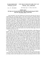
4. Summary of Test Method
4.1 The subthreshold charge separation technique is based
on standard MOSFET subthreshold current-voltage characteristics. The subthreshold drain or source current at a fixed drain
to source voltage, VDS, is measured as a function of gate
voltage from the leakage current (or limiting resolution of the
measurement apparatus) through inversion. The drain current
and gate voltage are related by IDα 10VG. When plotted as log
ID versus VG, the linear I-V characteristic can be extrapolated
to a calculated midgap current, IMG. By comparing the pre- and
post-irradiation characteristics, the midgap voltage shift, ∆VMG
can be determined. The value of ∆VMG is equal to ∆Vot, which
is the voltage shift due to oxide trapped charge. The difference
between the inversion voltage shift, ∆VINV, and ∆VMG is equal
to ∆Vit, which is the voltage shift due to interface traps. This
procedure is shown in Fig. 1 for a p-channel MOSFET.
6.2 Floating Body (Kink) Effects—Floating body effects
occur in MOSFETs without body (substrate) ties. This test
method should not be applied to a MOSFET without a
substrate or substrate/source contact.
6.3 Short Channel Effects—To minimize drain voltage dependence on the subthreshold curve, a small drain measurement voltage is recommended but not necessary.
6.4 Leakage Current—Because the MOSFET midgap current is below the capabilities of practical current-voltage
measurement instrumentation, extrapolation of the subthreshold swing is required for the determination of a MOSFET
midgap voltage. Extrapolation of ideal linear MOSFET subthreshold current-voltage characteristics is unambiguous, because of the constant subthreshold swing. An example of near
ideal subthreshold characteristics is given in Fig. 2, where the
FIG. 1 Determination of Radiation Induced Voltage Shift for
p-Channel MOSFET
FIG. 2 Near Ideal Subthreshold Characteristics from an
n-Channel Transistor
2
F996 − 11
subthreshold current swing is relatively constant between 10−11
and 10−6 A. Nonideal subthreshold characteristics, that are
aberrations from the theoretical linear subthreshold swing, can
complicate the subthreshold current swing extrapolation to the
midgap voltage. For subthreshold characteristics that have
multiple subthreshold swings, the value of the midgap voltage
would be dependent on the values of the subthreshold current
from which the extrapolation is made. Nonideal subthreshold
characteristics are caused by MOSFET leakage currents that
can be either independent of, or a function of, gate-source
voltage.
6.4.1 Junction Leakage Current—This leakage current is
from the drain to the substrate and is independent of gatesource voltage. Junction leakage current masks the actual
MOSFET channel subthreshold current below the leakage
current level. Junction leakage current is easily distinguished
from the channel subthreshold current as is shown in Fig. 2 by
the flat section of the drain current, ID, below 10−11A. This
figure also shows the advantage of using the source current, I
S, for extrapolation. The source current is not affected by
junction leakage so that a measure of the MOSFET channel
current is obtained to the instrumentation noise level. However,
if there is not a separate source and substrate contact (for
example, power MOSFETs), the drain current must be used.
Only the part of the subthreshold curve above the junction
leakage or instrumentation noise level should be used for
extrapolation. A minimum of two decades of source or drain
current above the leakage or noise is required for application of
this test method.
6.4.2 Gate Leakage—Gate leakage can be any combination
of leakage from the gate to source, drain, or substrate.
Typically this leakage will be a function of the gate-source
voltage. If gate leakage is greater than 1.0 µA for any
gate-source voltage, the test method should not be applied.
Gate leakages less than 1.0 µA can still cause nonideal
subthreshold characteristics. The minimum value of the subthreshold source or drain current used for extrapolation to the
midgap voltage must be above any changes in the subthreshold
swing that can be attributed to gate leakage. Plotting the log of
the gate leakage along with log source and drain current on the
same graph, will aid in the determination of gate leakage
effects on the drain and source subthreshold swing.
6.4.3 Edge Leakage Current—Most microcircuit MOSFETs
use an open geometry layout so that ionizing radiation induced
drain to source leakage can occur in n-channel devices outside
of the intentional MOSFET channel. The effect of this edge
leakage on the subthreshold swing is dependent on the aspect
ratios and threshold voltages of the intentional and parasitic
MOSFETs. The aspect ratio of the parasitic MOSFET would
usually be much smaller than a standard width MOSFET
layout. Thus, when the MOSFET channel is in strong
inversion, the channel current will typically dominate.
However, as the channel current is reduced, edge leakage can
go from a minimal fraction to dominating the measured drain
or source current if the parasitic MOSFET inversion voltage is
less than the intentional MOSFET. This effect can be observed
in the measured subthreshold characteristics as a deviation
from the ideal linear subthreshold curve that is a function of the
gate-source voltage. Examples of parasitic MOSFET induced
deviations from the ideal linear subthreshold swing are given in
Fig. 3 and Fig. 4. In Fig. 3, the subthreshold swing changes
from the initial swing near inversion to a much larger mV/
decade swing. In Fig. 4, a more pronounced deviation is
shown. The section of the subthreshold curve that should be
used for extrapolation to the midgap voltage is shown in both
figures. The upper section of the subthreshold curve above the
lower current level deviations was used. Any lower current
change in the subthreshold swing from the initial subthreshold
swing below strong inversion should be considered a parasitic
MOSFET induced deviation. Only the part of the subthreshold
curve above this deviation should be used for extrapolation as
is shown in Fig. 3 and Fig. 4. Some n-channel MOSFETs may
have post-irradiation edge leakage sufficiently large to prevent
any observation of a subthreshold swing. The subthreshold
charge separation technique cannot be applied to these
samples. A minimum of two decades of source or drain current
above any subthreshold swing deviation is required for application of this test method. Open and closed (annular) geometry
layouts can be used to separate edge leakage current from the
MOSFET channel current.
6.4.4 Backchannel and Sidewall Leakage in a SOI
MOSFET—In a silicon-on-insulator (SOI) MOSFET, the backchannel leakage arises from a parasitic MOSFET located at the
interface between the epitaxial silicon and the insulator. Sidewall leakages arise from the parasitic MOSFET formed at the
edges of the intentional MOSFET. These parasitics distort the
subthreshold curve in the same manner as described in 6.4.3.
7. Apparatus
7.1 To measure the subthreshold current-voltage characteristics of a MOSFET, the instrumentation required consists of,
as a minimum, two voltage sources and four ammeters.
7.2 The power supplies are used to apply voltage to the gate
and drain of the MOSFET. The ammeters are used to measure
the gate, drain, source, and substrate currents.
7.3 For MOSFETs that have a common source/substrate
contact, only three ammeters are required.
FIG. 3 Example of a Parasitic MOSFET Induced Deviation From
the Ideal Linear Subthreshold Swing
3
F996 − 11
8. Test Specimens and Sampling
8.1 Test Specimens—This test method can be applied to
MOSFETs in wafer form using a probe station or in package
form.
8.2 Sampling—This test method determines the properties
of a single MOSFET. If sampling procedures are used to select
MOSFETs for test, they must be agreed upon in advance by the
parties to the test.
9. Calibration
9.1 Determine the current noise levels of the apparatus for
measuring the MOSFET current-voltage characteristics. Perform a gate-source voltage sweep without a DUT in the test
fixture. If a probe station is being used, move the probes into
the proximity of each other which would be representative of
probing of the actual MOSFET. Record the gate, drain, source,
and substrate current noise levels.
FIG. 4 Example of a Parasitic MOSFET Induced Deviation from
the Ideal Linear Subthreshold Swing
10. Test Conditions
7.4 For a typical digital microcircuit MOSFET the voltage
sources and ammeters should meet the specification given in
Table 1.
10.1 This test method only describes the application of the
subthreshold charge separation technique. The total-dose irradiation test procedure, which, for example, includes the type of
irradiation exposure, the total-dose measurement interval(s),
the irradiation bias condition, the anneal bias condition, and the
time between irradiation and test, must be agreed upon in
advance by the parties to the test.
7.5 For a power, parasitic field oxide, or high voltage linear
MOSFET, the maximum voltage requirement for the gatesource power supply can be substantially larger. Field oxide
field effect transistor (FETs) may have pre-irradiation threshold
voltages of several hundred volts. The gate-source power
supply is required to be such that the MOSFET drain-to-source
subthreshold current can be measured from leakage into strong
inversion. The resolution of a gate-source power supply must
be at least 0.5 % of the maximum gate-source voltage, for the
MOSFET subthreshold current-voltage measurement.
10.2 MOSFET Type—p-channel or n-channel.
10.3 Before this test method can be implemented, the
gate-source and drain-source voltages that are appropriate for
the MOSFET type to be measured must be selected. These vary
from one MOSFET type to another.
10.3.1 The magnitude of the drain-source voltage used to
measure the subthreshold is recommended to be between 100
and 150 mV or the microcircuit Vcc. The drain-source voltage
is positive for an n-channel and negative for a p-channel. Since
the drain-source voltage, VDS, can influence the subthreshold
current-voltage characteristics because of short channel effects,
VDS must be agreed upon in advance by the parties to the test.
10.3.2 The gate-source voltage sweep range is adjusted to
measure the MOSFET subthreshold from leakage to a channel
current that is at least ten times the inversion current, IINV. The
gate-source voltage step size is adjusted so that a minimum of
two or three drain and source currents are measured per decade
of subthreshold current.
10.3.3 The source and substrate are grounded.
7.6 The test fixture, containing the MOSFET under test
(DUT), and the cabling connecting the test instrumentation,
must be designed for low current measurements specified in
Table 1. Probe stations can be used for MOSFETs in wafer
form as long as a current resolution of 100 pA can be
maintained.
7.7 The test fixture may be the same or different from the
fixture(s) used during irradiation and anneal (irradiation and
anneal fixture(s)). Any handling of the DUT must be performed
so as to minimize static discharge or other voltage transients
that may damage (alter current-voltage characteristics) the
DUT.
7.8 For control of measurement and data recording, the
subthreshold current-voltage characteristics can be measured
with a programmable tester having the proper current and
voltage capabilities, or with computer control of independent
power supplies and ammeters. To minimize apparatus setup,
programmable testers are usually selected.
10.4 Measure the DUT subthreshold current-voltage characteristics.
10.5 Determine the suitability of the application of this test
method to the DUT. Base the decision on the existence and
magnitude of the leakage currents discussed in 6.4.
10.5.1 Plot the log of all DUT currents versus the gatesource voltage on the same graph for comparison. The purpose
of plotting all currents is to analyze the DUT for junction and
gate leakage paths, and parasitics that can cause distortions of
the subthreshold drain or source curves, or both (see 6.4).
10.5.2 If the DUT is found unacceptable for this test
method, choose a new sample and return to 10.3.
TABLE 1 Minimal Instrumentation Specifications
Drain-source power supply
Gate-source power supply
Ammeters
±10 V, 0.01 V resolution
±10 V, 0.005 V resolution
±10 mA, 10 pA resolution
4
F996 − 11
10.6 Decide on whether the source or drain current will be
used for application of this test method. Use the source current,
unless the source and substrate contacts are common or if the
subthreshold drain current has less junction and gate leakage
current than the source current. For these two cases, use the
drain current.
the MOSFET is in the linear region of operation, that is
normally the case for a VDS of 100 to 150 mV. If:
V DS $ V GS 2 V INV,
the MOSFET is in the saturated region of operation.
12.2.3 If the MOSFET is in the linear region of operation,
then:
11. Procedure
K 5 G M /V DS.
11.1 Pre-Irradiation Characterization:
11.1.1 Select the circuit configuration for subthreshold measurement (see10.2).
11.1.2 Program the gate-source voltage range and the drainsource voltage (if applicable) to measure the DUT subthreshold
current-voltage characteristics (see 10.3).
11.1.3 Insert the DUT into the test fixture.
11.1.4 Measure the DUT subthreshold current-voltage characteristics. Record the gate, drain, source, and substrate currents (providing all contacts are available) versus the gatesource voltage.
11.1.5 If necessary, remove the DUT from test fixture and
insert the DUT into the irradiation fixture (see 7.7).
11.1.6 Apply irradiation bias as soon as possible and perform DUT irradiation.
12.2.4 If the MOSFET is in the saturation region of
operation, then:
K 5 G M / ~ V GS 2 V INV! .
12.2.5 An example of a plot of ∆ Ic/∆VGS versus VGS is
given in Fig. 5. The maximum value from this plot is the value
of GM used to solve for K.
12.3 Calculate Midgap and Inversion Currents:
12.3.1 Obtain values for N and tox from the semiconductor
facility that processed the DUT. Approximate values can be
used for these parameters. A factor of 3 error in N is usually
sufficient for a 65 % error in ∆Vot and ∆Vit.
12.3.2 The values of midgap and inversion currents, IMG
and IINV, are found from the following equations:
11.2 Post-Irradiation Characterization:
11.2.1 If necessary, remove the DUT from the irradiation
fixture and insert the DUT into the test fixture (see 7.7).
11.2.2 Adjust the programmed gate-source voltage range (if
applicable) to compensate for the ionizing radiation-induced
inversion voltage shift (see 10.3.2).
11.2.3 Measure the DUT subthreshold current-voltage characteristics. Record the gate, drain, source, and substrate currents versus the gate-source voltage.
11.2.4 If irradiation or anneal testing, or both, are to
continue, perform the next two steps.
11.2.4.1 If necessary, remove DUT from test fixture and
insert in the irradiation fixture or an anneal fixture (see 7.7).
11.2.4.2 Apply irradiation or anneal bias as soon as possible
and perform DUT irradiation if applicable.
I MG 5 K
a
2β 2
I INV 5 K
a
2β 2
S D~
S D~
a5
LD 5
φB 5
ni
N
2
ni
N
2
e βφB
βφ B 2 1 ! 1/2
(1)
e 2βφB
2βφ B 2 1 ! 1/2
(2)
= 2ε s t ox
S D
S D
kTε s
Nq2
1/2
(4)
kT
N
ln
q
ni
(5)
q
kT
(6)
β5
where:
n i = intrinsic carrier concentration = 1.01 × 1010 cm
at
12. Calculation
(3)
ε oxL D
−3
12.1 Perform all test method calculations using the DUT
source or drain current, Ic, based on the decision in 10.5.
12.2 Calculate a Value for the Transconductance—The
value of the transconductance is obtained from the preirradiation Ic and the gate-source voltage, VGS, data. The
pre-irradiation value of transconductance is used in the analysis
of all the post-irradiation and anneal measurements.
12.2.1 The value of the transconductance, GM, is the maximum slope from the plot of the pre-irradiation Ic versus VGS
data. The value of the transconductance can be more easily
obtained from the plot of the pre-irradiation ∆Ic/∆VGS versus
VGS. The maximum value of ∆Ic/∆VGS corresponds to the
maximum slope from the Ic versus VGS plot.
12.2.2 Determine the value of VGS that corresponds to the
chosen value of GM. If the value of GM is constant for a range
of V GS, then use the minimum value of VGS. If:
FIG. 5 Plot ofGM Versus Gate Voltage for Drain Voltage of 0.1 V
V DS,V GS 2 V INV,
5
F996 − 11
and
~ 300 K ! 5 3.87 3 1016 T 3/2 exp~ 20.605 q/kT! cm23 ,
εs
εox
q
k
T
∆V it 5 ∆V INV 2 ∆V MG.
−12
= silicon dielectric constant = 1.05 × 10
F/cm,
= oxide (insulator) dielectric constant = 3.45 × 10
F/cm,
= elementary charge = 1.60 × 10⁻¹⁹ C,
= Boltzmann constant = 1.38 × 10⁻²³ J/K, and
= temperature in Kelvin.
−13
These values are obtained for each post-irradiation and
anneal measurement.
13. Report
13.1 Describe the facility used to irradiate the DUT(s) by
the following information:
13.1.1 Type of facility (for example, x-ray or 60Co), and
13.1.2 Dose rate in rd(SiO2)/s.
12.3.3 The values of the midgap and inversion currents
calculated from the pre-irradiation MOSFET data are used in
the calculation of ∆VINV and ∆VMG for all post-irradiation and
anneal measurements.
13.2 For each DUT, report the following:
13.2.1 Semiconductor facility that processed the DUT and
the process if available,
13.2.2 DUT identification number,
13.2.3 Value of N,
13.2.4 Value of t ox,
13.2.5 Value of G M,
13.2.6 Irradiation, anneal, and measurement temperatures,
13.2.7 Irradiation biases, and
13.2.8 Whether the drain or source current was used in the
calculations.
12.4 Calculate ∆VINV. These calculations are performed for
each post-irradiation and anneal measurement.
12.4.1 Find the pre-irradiation value of the inversion
voltage, VINVI. The value of VINVI, that corresponds to the
calculated value of IINV, is found from the pre-irradiation Ic
versus VGS data by using linear interpolation between the two
closest measurements on either side of the inversion current,
IINV.
12.4.2 Find the post-irradiation value of the inversion
voltage, VINVγ . The value of VINVγ is found from the postirradiation Ic versus VGS data using linear interpolation as in
12.4.1.
12.4.3 The value of ∆VINV is given by:
∆V INV 5 V INVγ 2 V
13.3 For each application of the test method, report the
following:
13.3.1 Total dose in rd(SiO2),
13.3.2 Time between last irradiation and subthreshold
measurement,
13.3.3 Anneal bias between last irradiation and subthreshold measurement,
13.3.4 The minimum and maximum subthreshold current
values used in the linear least squares fit to find the midgap
voltage,
13.3.5 The maximum value of the junction leakage current,
and
13.3.6 The values of ∆Vot and ∆Vit.
.
INVI
12.5 Calculate ∆VMG. These calculations are performed for
each post-irradiation and anneal measurement.
12.5.1 Find the pre-irradiation value of midgap voltage,
VMGI. The value of VMGI is found from the pre-irradiation log
Ic versus VGS data by extrapolation to the calculated midgap
current, IMG. Because the value of the midgap current is
typically much less than the measurement accuracy of the
apparatus, the value of midgap voltage is found by extrapolation of the linear section of the subthreshold log IC versus VGS
curve to the value of the midgap current as shown in Fig. 1
through Figs. 3 and Fig 4 (see 6.4). Extrapolate the subthreshold curve to the midgap current, IMG, using a linear least
squares fit to the Ic data. The maximum and minimum values
of Ic data used for the least squares fit can be defined by the
parties to the test or by the user (see 12.1). The minimum and
maximum Ic values must be on the linear section of the
subthreshold curve (see 6.4). These values can be determined
after the irradiation of the DUT and must be identical for the
pre-irradiation and all post-irradiation measurements used in
the calculation of results.
12.5.2 Find the post-irradiation value of midgap voltage,
VMGγ. The value of VMGγ is found from the pre-irradiation log
Ic versus VGS data by extrapolation of the linear least squares fit
to the calculated midgap current (see 12.5.1).
12.5.3 The value of ∆ VMG is given by:
14. Precision and Bias6
14.1 Precision—An interlaboratory experiment was conducted with five laboratories and the coordinating lab participating. Four additional laboratories had planned on participating but did not complete the study.
14.1.1 Each participating laboratory was asked to perform
measurements according to this test method using the samples
provided. A sample consisted of a pair of packaged parts, one
irradiated to 500 Krd(SiO2) (plus 24 h 80°C bake) and the
second was not irradiated. Each packaged part contained 6
MOSFETs, 3 n-channel and 3 p-channel MOSFETs (16 àm ì
2, 3, and 4 µm). Devices were labeled based on the geometry
and type, for example, the unirradiated 2 µm n-channel
transistor on Sample A is labeled A2n and the irradiated 2 µm
n channel transistor sample is labeled A2n(rad). One laboratory
tested all nine sample pairs, one laboratory tested four of the
nine, and the remaining three laboratories each tested one pair.
14.1.2 The original plan was to assume device-device variations to be insignificant, as all devices came from the same
∆V MG 5 V MGγ 2 V MGI.
12.6 The values for the radiation induced voltage shift due
to oxide trapped charge, ∆Vot, and the voltage shift due to
interface traps, ∆Vit, are given by:
6
Supporting data have been filed at ASTM International Headquarters and may
be obtained by requesting Research Report RR:F01-1014.
∆ V ot 5 ∆V MG
6
F996 − 11
with the test method. The worst case standard deviation of the
mean measured values was 25 % of the mean, and the 95 %
confidence reproducibility limit is 35 %. Although this study
did not attempt to measure the repeatability, it is on the order
of 1–2 % (dependent on the equipment used to measure I–V
characteristics) and is an insignificant component of the
precision in this case.
14.1.4 The reproducibility of this test method was determined to be 35 % (95 % confidence limit). The precision is
essentially the same as the reproducibility, as the repeatability
is insignificant compared to the reproducibility.
diffusion lot, and to base comparisons on testing done on
different samples at the different laboratories. Device-device
uniformity, however, was not good, and comparisons were
made only where at least three laboratories tested the same
device.
14.1.3 Table 2 provides the comparison of Vot and Vit for
four devices and four laboratories. The high attrition was due
to damaged devices and to devices screened out in accordance
TABLE 2 Interlaboratory Test Data
Laboratory
1
2
3
4
Mean
Standard
Deviation
Percent
Delta Vit (V)
Delta Vot (V)
A3n
A2n
F3n
A4p
A3n
A2n
F3n
1.269 1.298 1.282 –0.637 –0.512 –0.479 –0.537
1.29
1.47
1.29
–1.07 –0.56 –0.59 –0.62
0.971
–0.546
1.02 1.231
–0.903 –0.603 –0.55
1.193 1.333 1.181 –0.870 –0.558 –0.540 –0.568
0.150 0.123 0.182
0.218 0.046 0.056 0.046
12.6 %
9.2 % 15.4 % 25.1 %
8.2 % 10.4 %
8.0 %
A4p
–0.476
–0.44
14.2 Bias—The bias for this test method has not been
determined since there is no suitable reference material.
–0.65
–0.522
0.112
15. Keywords
15.1 c/v characteristics; current–voltage characteristics; interface states; ionizing radiation; MOSFET; oxide-trapped
holes; threshold voltage shift; trapped holes
21.5 %
ASTM International takes no position respecting the validity of any patent rights asserted in connection with any item mentioned
in this standard. Users of this standard are expressly advised that determination of the validity of any such patent rights, and the risk
of infringement of such rights, are entirely their own responsibility.
This standard is subject to revision at any time by the responsible technical committee and must be reviewed every five years and
if not revised, either reapproved or withdrawn. Your comments are invited either for revision of this standard or for additional standards
and should be addressed to ASTM International Headquarters. Your comments will receive careful consideration at a meeting of the
responsible technical committee, which you may attend. If you feel that your comments have not received a fair hearing you should
make your views known to the ASTM Committee on Standards, at the address shown below.
This standard is copyrighted by ASTM International, 100 Barr Harbor Drive, PO Box C700, West Conshohocken, PA 19428-2959,
United States. Individual reprints (single or multiple copies) of this standard may be obtained by contacting ASTM at the above
address or at 610-832-9585 (phone), 610-832-9555 (fax), or (e-mail); or through the ASTM website
(www.astm.org). Permission rights to photocopy the standard may also be secured from the ASTM website (www.astm.org/
COPYRIGHT/).
7