Astm f 1999 14
Bạn đang xem bản rút gọn của tài liệu. Xem và tải ngay bản đầy đủ của tài liệu tại đây (94.32 KB, 4 trang )
Designation: F1999 − 14
Standard Practice for
Installation of Rigid Poly(Vinyl Chloride) (PVC) Fence
Systems1
This standard is issued under the fixed designation F1999; the number immediately following the designation indicates the year of
original adoption or, in the case of revision, the year of last revision. A number in parentheses indicates the year of last reapproval. A
superscript epsilon (´) indicates an editorial change since the last revision or reapproval.
1. Scope
Alloy Steel Bars for Concrete Reinforcement
D2564 Specification for Solvent Cements for Poly(Vinyl
Chloride) (PVC) Plastic Piping Systems
F964 Specification for Rigid Poly (Vinyl Chloride) (PVC)
Exterior Profiles Used for Fencing and Railing
1.1 This practice covers the minimum requirement for and
methods of installation for rigid poly(vinyl chloride) (PVC)
fencing systems and fence accessories in areas where the
maximum frost penetration does not exceed 30 in. [76 cm]. In
all cases, refer also to the specific manufacturer’s instructions
for installation.
3. Terminology
1.2 This practice is intended to guide those responsible for
or concerned with installation of rigid (PVC) fence systems.
3.1 Definitions of Terms Specific to This Standard:
3.1.1 clip—a component used to lock rails into routed posts.
1.3 This practice does not preclude any test method that is
proven to give equal or better performance under any weather,
soil, or frost conditions.
3.1.2 corner post—a post that accepts fence rails so that a
fence ends in one direction and starts in another, more or less,
perpendicular direction.
1.4 End-use and applicable code requirements shall be
considered in the choice of fence style, spacing, height, and
installation method.
1.4.1 Paddock fencing for livestock may need to be more
durable than perimeter fence.
1.4.2 Residential fence styles may not be designed for
balcony or guardrail use.
3.1.3 end cap—a component to cover the open end of a rail
or other extrusion.
3.1.4 end post—the end or last vertical structural support
member of the fence.
3.1.5 exterior profile—a rigid poly(vinyl chloride) (PVC)
extrusion that conforms to Specification F964.
3.1.6 gate—a hinged panel for passage into or out of a
fenced area.
1.5 The values stated in inch-pound units are to be regarded
as standard. The values given in brackets are for information
only.
1.6 This standard does not purport to address all of the
safety concerns, if any, associated with its use. It is the
responsibility of the user of this standard to establish appropriate safety and health practices and determine the applicability of regulatory limitations prior to use.
3.1.7 hinge post—the post to which a gate is attached.
3.1.8 notch—a method of creating a tab used to lock rails
into routed posts.
3.1.9 outside brackets—components used to fasten rails to
the outside of posts, when routed posts are not used.
3.1.10 picket—a vertical member in a fence panel, between
or attached to the horizontal members.
2. Referenced Documents
3.1.11 picket cap—a component used to cover or decorate
the open end(s) of picket.
2.1 ASTM Standards:2
A706/A706M Specification for Deformed and Plain Low-
3.1.12 post cap—a component used to cover the top of a
post.
1
This practice is under the jurisdiction of ASTM Committee F14 on Fences and
is the direct responsibility of Subcommittee F14.30 on Rigid Polymer Fence
Systems.
Current edition approved Aug. 1, 2014. Published August 2014. Originally
approved in 2000. Last previous edition approved in 2006 as F1999 - 00(2006).
DOI: 10.1520/F1999-14.
2
For referenced ASTM standards, visit the ASTM website, www.astm.org, or
contact ASTM Customer Service at For Annual Book of ASTM
Standards volume information, refer to the standard’s Document Summary page on
the ASTM website.
3.1.13 posts—the vertical structural support members of the
fence.
3.1.14 rails—the horizontal members which insert into or
attach to the posts. They serve as the sole sections between
posts or as back rails to which picket verticals are attached.
3.1.15 routed posts—posts with holes cut into them to allow
rails to be inserted.
Copyright © ASTM International, 100 Barr Harbor Drive, PO Box C700, West Conshohocken, PA 19428-2959. United States
1
F1999 − 14
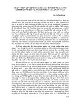
7.3 Installation of Posts—This practice includes post setting
methods. Careful consideration should be taken to choose the
correct method based on soil types at the installation location.
7.3.1 Method 1—Partially fill holes with concrete, then set
the post into the concrete leaving approximately 2 to 4 in. [51
to 101 mm] of concrete below the bottom of the post (see Fig.
1). Continue filling the hole with concrete to within 6 to 9 in.
[152.4 to 228.6 mm] of the top. Fill the remainder of the hole
with soil or fine rocks. Where frost is not likely, the hole may
be filled to ground level with concrete (see Note 1). The post
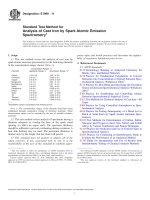
shall extend a minimum of 18 in. [457.2 mm] into the concrete
(see Fig. 2). Check to see that the post remains plumb until the
concrete has set.
4. Materials
4.1 Exterior Profiles, in accordance with Specification
F964.
4.2 Solvent Cement— Poly(Vinyl Chloride) (PVC) solvent
cement in accordance with Specification D2564.
4.3 Reinforcing Steel Rods, in accordance with Specification
A706/A706M low-alloy steel deformed bars for concrete
reinforcement.
5. Protection of Material in Transportation and Storage
5.1 Exterior profiles shall be supported in a manner that will
prevent sagging, twisting, or bending. Fence products shall be
stored in a manner that prevents accumulation of dust and dirt.
Exposure to sunlight is not harmful.
NOTE 1—Filling hole to top with concrete in frost areas will enhance
upheaval of post and footers as concrete freezes faster than fill.
7.3.2 Method 2—Tap the post into the bottom of the hole
until the desired height of the post above ground level is
reached (see Note 2 and Fig. 3). Add concrete around the post
to the level specified in 7.3.1. Check to see that the post
remains plumb until the concrete has set.
6. Site Preparation
6.1 Unless otherwise specified in the contract or purchase
order, the purchaser shall indicate the location of fence lines,
gates, and terminal posts with suitable stakes. Stake intervals
shall not exceed 500 ft [152.5 m] or line of sight.
NOTE 2—This method should not be used where there are mucky or
loose soil conditions as without concrete under the post, it may sink if
downward pressure is applied.
6.2 Unless otherwise specified in the contract or purchase
order, the purchaser shall indicate the location of all underground utilities, USC&G benchmarks, property monuments,
and other underground structures.
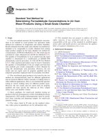
7.3.3 Method 3—Tap the post into the bottom of the hole
until the desired height of the post above ground level is
reached (see Fig. 4). Fill the hole one fourth of the depth with
concrete, then add fine rocks or gravel to one half of the depth
of the hole, then add concrete to three fourths of the depth of
the hole. Fill the remainder of the hole with soil, gravel, or fine
rocks (see Note 1). Check to see that the post remains plumb
until the concrete has set.
7.3.4 Method 4—Place 4–6 inches of crushed stone in the
bottom of the post holes, then set the post into the hole and
continue filling in around the post with crushed stone to within
four inches of grade. Compact the stone with a solid
instrument, such as a breaker bar or heavy steel rod. Fill the
remainder of the hole with soil or fine rocks.
6.3 Unless otherwise specified in the contract or purchase
order, the purchaser shall perform all necessary site clearing
and grading. Clearance on both sides of the fence line is
required.
7. Installation of Posts
7.1 Preparation of Post Holes:
7.1.1 Set posts in concrete in holes of diameter and depth as
follows. Intended use and local conditions shall determine post
footing dimensions, that is, under normal conditions the
diameter shall be 4 in. [101 mm] greater than the largest cross
section of the post. The depth shall be a minimum of 24 in.
[609 mm] plus an additional 3 in. [76 mm] for each 1-ft
[305-mm] increased fence height over 4 ft [1.22 m].
7.1.2 In areas where frost is common, the footing shall
extend a minimum of 6 in. [152.4 mm] below the maximum
frost level.
7.2 Preparation of Post—To secure post vertically, provide
a means such as, but not limited to, notching, drilling,
roughing, pinning, etc.
TABLE 1 Thermal Expansion in Inches [Millimetres ] for PVC
Fence ProfilesA
Rail Length,
ft [m]
6
8
10
12
14
16
[1.8]
[2.44]
[3.05]
[3.6]
[4.27]
[4.88]
80°F Temperature
Change
⁄
3 32
⁄
18
⁄
⁄
7⁄32
1⁄ 4
5 32
3 16
[2.38]
[3.2]
[3.97]
[4.76]
[5.55]
[6.4]
100°F
Temperature
Change
1 ⁄8
[3.2]
5⁄32
[3.97]
3⁄16
[4.76]
7⁄32
[5.55]
9⁄32
[7.14]
5⁄16
[7.94]
120°F
Temperature
Change
5⁄32
[3.97]
3⁄16
[4.76]
1⁄ 4
[6.4]
9⁄32
[7.14]
11⁄32
[8.73]
3⁄ 8
[9.53]
A
These values are calculated using a coefficient of linear thermal expansion of 4.4
× 10−5 in./ in./ °F.
FIG. 1
2
F1999 − 14
FIG. 2
FIG. 4
FIG. 5
9. Installation of Post Caps and Picket Tops, etc.
9.1 Post caps, end caps, and picket caps, if not pre-fastened
by the manufacturer, shall be attached in accordance with the
manufacturer’s recommendation, or by noncorrosive fasteners,
or by solvent cement bonding.
FIG. 3
10. Installation of Gates on Posts
10.1 Gate hinge posts require more support than line posts.
Follow the manufacturer’s instructions regarding the use of
inserts to minimize deflection.
NOTE 3—This method looks very similar to Fig. 1, with crushed stone
in place of the concrete.
NOTE 4—Method 4 is to be used in soil types that tend to crack open
when dry as to help reduce post settling during dry conditions.
10.2 Install gates true to opening and plumb in a closed
position.
8. Installation of Rails and Sections
10.3 Gates shall operate freely, and closures shall be properly installed in accordance with all applicable codes and the
manufacturer’s recommendations.
8.1 Explanation or contraction values for fence profiles are
given in Table 1. Rails shall extend into routed posts with
sufficient distance between notches or clips, etc. and the inside
wall of the post to accommodate the given contraction. When
two rails are inserted into a post, end to end, a gap shall be
provided between them for expansion. In all cases, rails shall
extend a minimum of 1 in. [25.4 mm] into routed posts. The
fractional dimensions shown in Table 1 are applied to both
ends of the rail.
10.4 Unless specified by an applicable code, the purchaser
shall indicate the operational direction of the gates.
11. Appearance
11.1 The areas of installation shall be left neat and free of
any debris caused by the installation of fence.
8.2 If outside brackets are used, they shall be fastened
securely with noncorrosive fasteners in accordance with the
manufacturer’s instructions.
12. Keywords
12.1 fence; installation; rigid poly(vinyl chloride) (PVC)
3
F1999 − 14
ASTM International takes no position respecting the validity of any patent rights asserted in connection with any item mentioned
in this standard. Users of this standard are expressly advised that determination of the validity of any such patent rights, and the risk
of infringement of such rights, are entirely their own responsibility.
This standard is subject to revision at any time by the responsible technical committee and must be reviewed every five years and
if not revised, either reapproved or withdrawn. Your comments are invited either for revision of this standard or for additional standards
and should be addressed to ASTM International Headquarters. Your comments will receive careful consideration at a meeting of the
responsible technical committee, which you may attend. If you feel that your comments have not received a fair hearing you should
make your views known to the ASTM Committee on Standards, at the address shown below.
This standard is copyrighted by ASTM International, 100 Barr Harbor Drive, PO Box C700, West Conshohocken, PA 19428-2959,
United States. Individual reprints (single or multiple copies) of this standard may be obtained by contacting ASTM at the above
address or at 610-832-9585 (phone), 610-832-9555 (fax), or (e-mail); or through the ASTM website
(www.astm.org). Permission rights to photocopy the standard may also be secured from the Copyright Clearance Center, 222
Rosewood Drive, Danvers, MA 01923, Tel: (978) 646-2600; />
4