Astm f 2754 f 2754m 09 (2013)
Bạn đang xem bản rút gọn của tài liệu. Xem và tải ngay bản đầy đủ của tài liệu tại đây (136.67 KB, 4 trang )
Designation: F2754/F2754M − 09 (Reapproved 2013)
Standard Test Method for
Measurement of Camber, Cast, Helix and Direction of Helix
of Coiled Wire1
This standard is issued under the fixed designation F2754/F2754M; the number immediately following the designation indicates the year
of original adoption or, in the case of revision, the year of last revision. A number in parentheses indicates the year of last reapproval.
A superscript epsilon (´) indicates an editorial change since the last revision or reapproval.
2.2.2.1 helix (free end lift)—the maximum lift of the free
end of the wire when laid on a flat surface, Fig. 1(b).
2.2.2.2 helix (hanging helix)—the maximum distance between two adjacent coils of wire, Fig. 1(c). A hanging helix can
also be measured by suspending the coils.
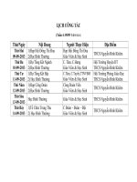
2.2.3 helix direction—can be left— or right-handed depending upon how the wire was coiled, Fig. 1(d)
2.2.3.1 left-handed helix—the wire is coiled in a counterclockwise direction, Fig. 2(a).
2.2.3.2 right-handed helix—the wire is coiled in a clockwise
direction, Fig. 2(b).
2.2.4 camber—the deflection in the width direction of a flat
or shaped wire, Fig. 1(e).
1. Scope
1.1 This test method covers the various standard methods
that are used for measuring camber, cast, helix, and helix
direction. The wire may be coiled with or without a spool.
1.2 This test method applies to round wire that has a
diameter between 0.0127 to 4.78 mm (0.0005 to 0.188 in.). It
also applies to flat or shaped wire.
1.3 This test method does not apply to superelastic nitinol
wire. It does apply to the as-drawn condition of nitinol wire.
1.4 This test method does not apply to the measurement of
the straightness of straightened to length wire and tubing.
1.5 The values stated in either SI units or inch-pound units
are to be regarded separately as standard. The values stated in
each system may not be exact equivalents; therefore, each
system shall be used independently of the other. Combining
values from the two systems may result in non-conformance
with the standard.
3. Summary of Test Method
3.1 The maximum diameter of at least one complete circumference is measured using a linear scale while it is resting
completely flat on a flat surface such as a table, workbench, or
floor (cast measurement). The maximum lift of the free end of
the wire when laid on a flat surface is the free end lift helix and
is measured using a linear scale. A hanging helix can be
measured using a linear scale while the wire is being suspended
(hanging helix free end lift). Camber is the offset in the width
dimension of a flat or shaped wire and can also be measured
using a linear scale while the wire is resting on a flat surface.
Alternatively, a coordinate measurement machine or optical
comparator may be used. Helix direction is the direction which
the wire has been coiled.
1.6 This standard does not purport to address all of the
safety concerns, if any, associated with its use. It is the
responsibility of the user of this standard to establish appropriate safety and health practices and determine the applicability of regulatory limitations prior to use.
2. Terminology
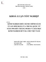
2.1 Fig. 1(a) through Fig. 1(e) illustrate the physical meaning of cast, helix, direction of helix, and camber.
2.2 Definitions:
2.2.1 cast—the maximum diameter of coiled wire when one
complete circumference rests completely on a flat surface such
as a table, workbench, or floor. Fig. 1(a).
2.2.2 helix—there are two common methods for measuring
helix—free end lift and hanging helix. These definitions are
defined by Fig. 1(b) and Fig. 1(c), respectively.
4. Significance and Use
4.1 The process of coiling wire causes the wire to take on a
curvature from the process of being mechanically deformed
into a coiled geometry. The curvature in the wire is permanent
unless the wire is straightened. It will affect how the coiled
wire will react when it is subjected to additional wire forming
operations. In addition, residual stresses induced from the
coiling operation can cause elastic recoil or spring back in
subsequent wire forming operations unless the material is
straightened and stress relieved prior to forming. These residual stresses can create wide variations in the dimensions of
components and or parts that have been built using the coiled
wire (cast).
1
This test method is under the jurisdiction of ASTM Committee F04 on Medical
and Surgical Materials and Devices and is the direct responsibility of Subcommittee
F04.15 on Material Test Methods.
Current edition approved Oct. 1, 2013. Published October 2013. Originally
approved in 2009. Last previous edition approved in 2009 as F2754/F2754M – 09.
DOI: 10.1520/F2754_F2754M-09R13.
Copyright © ASTM International, 100 Barr Harbor Drive, PO Box C700, West Conshohocken, PA 19428-2959. United States
1
F2754/F2754M − 09 (2013)
NOTE 1—(a) Definition of cast. (b) Definition of helix as measured by lift method. (c) Definition of helix as measured by hanging method. (d) Definition
of helix direction. (e) Definition of camber.
FIG. 1 Standard Definitions for Cast, Helix, and Camber of Spooled Wire
NOTE 1—(a) Definition of left-handed helix direction. (b) Definition of right-handed helix direction.
FIG. 2 Standard Definition for Direction of Helix
4.2 The direction that the wire has been coiled affects how
the wire will be taken off of the coil for subsequent wire
forming operations (helix direction).
5.3 Special equipment is not required for measurement of
camber, helix, or the direction of helix.
4.3 Lift or spacing between adjacent coils also affects how
the wire will be taken off of the coil and can also affect the
dimensions of components and or parts that have been built
using the coiled wire due to residual stresses (helix).
6. Test Specimen
6.1 Test Specimen for Measuring Cast:
6.1.1 It is preferred to fixture the spool or coil in a suitable
manner so it does not move as the wire is removed. It is
important to keep a firm tension on the wire to prevent tangling
which could alter the measurement.
6.1.2 Scrap the first 1.5 to 3 m (5 to 10 ft) of wire in order
to eliminate any possible end effects and wire damage from
being tied off. Ensure that the wire is easily coming off of the
spool or coil without any crossing over of the wire.
6.1.3 Allow the uncoiled wire to naturally form at least one
complete circle that rests completely flat on a level surface
such as a smooth table, bench, or the floor.
5. Apparatus
5.1 A linear scale is required for measurement of the cast of
coiled wire. An alternate approach is to use a profilometer or
coordinate measurement machine.
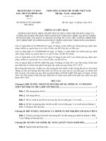
5.2 A template is useful for measuring the cast of coiled
wire that is greater than 0.6 m (24 in), Fig. 3. An alternative
approach is to use a coordinate measurement machine or
optical comparato
2
F2754/F2754M − 09 (2013)
FIG. 3 Example of a Template Used for Measuring Large Diameter Spooled Wire Cast
If the cast is greater than 1 m (36 in.), use a sectioned piece of
wire as is described in 6.1.4. The sectioned piece of wire
should be slid on the template until the curvature matches as
closely an arc on the template. This is the cast measurement
and should be measured in 0.25 m (10 in.) increments or as is
specified on the production order. An alternate approach is to
use a optical comparator or coordinate measurement machine.
6.1.4 For wire with a cast 1 m or greater (or 36 in. or
greater), cut a section of wire 0.5 m (18 in.) in length from the
spool.
6.2 Test Specimen for Determining the Direction of Helix—
Cut enough wire from the spool or coil for approximately 2 to
4 full diameters of the natural cast of wire. It is important to
keep tension on the wire as it is unspooled in order to prevent
tangling which could effect the measurement.
7.2 Determination of the Direction of Helix:
7.2.1 Suspend the wire specimen described in 6.2 by grasping it between a couple of fingers or by suspending it on a
straight object such as an ink pen and observe the direction that
it spirals away from you.
7.2.1.1 A right hand helix spirals away from you in a
clockwise direction, Fig. 2(a). A left hand helix spirals away
from you in a counterclockwise direction, Fig. 2(b).
6.3 Test Specimen for Measurement of Helix:
6.3.1 Free Lift Method—Remove approximately 2 to 4 full
diameters of the natural cast of the wire and allow them to rest
on a flat surface. It is important to keep tension on the wire as
it is unspooled in order to prevent tangling which could effect
the measurement.
6.3.2 Hanging Method—Remove approximately 2 to 4 full
diameters of the natural cast of the wire and suspend them
using your index finger. It is important to keep tension on the
wire as it is unspooled in order to prevent tangling which could
effect the measurement.
7.3 Measurement of Helix of Coiled Wire:
7.3.1 Measurement of Helix by Free End Lift Method—
Using the wire specimen described in 6.3.1 if the free end does
not lift from the top of the flat surface, the wire has a zero lift
by the free end lift method. If a lift is observed, use a linear
scale to measure the amount of maximum spacing between the
free end and adjacent coil. If the free end lift is between 0 to 25
mm (0 to 1 in.), the helix shall be reported to the nearest 10 mm
(0.25 in.). If the free end lift is greater than 25 mm (1 in.), the
helix shall be reported to the nearest 15 mm (0.5 in.). This
procedure is to be used to measure and report the free end lift
unless agreed upon otherwise between the purchaser and
supplier. An optical comparator or coordinate measurement
machine can be used alternatively to measure helix.
7.3.2 Measurement of Helix by Suspension (Hanging)
Method:
7.3.2.1 Using the test specimen described in 6.3.2, the
suspended or hanging helix is measured using a linear scale at
the point of maximum separation at the bottom of the loop.
One complete diameter of wire should be removed from the
spool and suspended on a straight shaft. Hanging helix should
be reported in 1 cm (0.5 in.) increments unless agreed upon
otherwise between the purchaser and the supplier.
6.4 Test Specimen for Measurement of Camber in Flat or
Shaped Wire—A cut length, typically 30 cm (12.0 in.), or as
agreed upon between the purchaser and supplier, should be
removed from the spool or coil.
7. Procedure
7.1 Measurement of Cast:
7.1.1 Allow the test specimen to form at least one complete
circle that rests completely flat on a level surface such as a
smooth table, bench, or the floor.
7.1.1.1 For wire with a cast less than 2.5 cm (1 in.), measure
the cast at the largest diameter of the circle using a linear scale,
profilometer, or coordinate measurement machine. The cast
should be rounded to the closest 5 mm (0.25 in.) measurement.
For wire with a cast between 2.5 cm (1 in.) and less than 1 m
(36 in.), measure the cast at the largest diameter of the circle
using a linear scale, optical comparator, or coordinate measurement machine. The cast should be rounded to the closest 2.5
cm (1 in.) measurement or as is specified on the purchase order.
3
F2754/F2754M − 09 (2013)
8.1.1 Material and sample identification.
8.1.2 Cast reported in SI or inch-pounds units as requested
by the purchaser.
8.1.3 Helix in SI or inch-pounds units as requested by the
purchaser.
8.1.4 Direction of the helix if it has been requested by the
purchaser.
8.1.5 Camber reported in SI or inch-pounds units as requested by the purchaser for flat or shaped wire.
7.3.2.2 Use of background lighting or a distinct in color
background will enhance the visibility of the helix when
smaller diameter wire is being measured.
7.4 Measurement of Camber in Flat or Shaped Wire—Using
the wire specimen described in 6.4, the amount of camber
should be measured using a linear scale. Place the cut length of
wire on a flat surface with the two cut ends of the wire against
a straight edge. The camber value is the distance between the
straight edge and inside radius of the wire. See Fig. 1(e).
Report the amount of camber present to the closest 3 mm
(0.125 in.) unless otherwise agreed upon by the purchaser and
the supplier.
9. Keywords
9.1 camber; coil; helix; helix direction
8. Report
8.1 The report shall include the following information
unless otherwise specified:
ASTM International takes no position respecting the validity of any patent rights asserted in connection with any item mentioned
in this standard. Users of this standard are expressly advised that determination of the validity of any such patent rights, and the risk
of infringement of such rights, are entirely their own responsibility.
This standard is subject to revision at any time by the responsible technical committee and must be reviewed every five years and
if not revised, either reapproved or withdrawn. Your comments are invited either for revision of this standard or for additional standards
and should be addressed to ASTM International Headquarters. Your comments will receive careful consideration at a meeting of the
responsible technical committee, which you may attend. If you feel that your comments have not received a fair hearing you should
make your views known to the ASTM Committee on Standards, at the address shown below.
This standard is copyrighted by ASTM International, 100 Barr Harbor Drive, PO Box C700, West Conshohocken, PA 19428-2959,
United States. Individual reprints (single or multiple copies) of this standard may be obtained by contacting ASTM at the above
address or at 610-832-9585 (phone), 610-832-9555 (fax), or (e-mail); or through the ASTM website
(www.astm.org). Permission rights to photocopy the standard may also be secured from the Copyright Clearance Center, 222
Rosewood Drive, Danvers, MA 01923, Tel: (978) 646-2600; />
4