Tiêu chuẩn iso 17268 2012
Bạn đang xem bản rút gọn của tài liệu. Xem và tải ngay bản đầy đủ của tài liệu tại đây (639.59 KB, 40 trang )
INTERNATIONAL
STANDARD
ISO
17268
Second edition
2012-12-01
Gaseous hydrogen land vehicle refuelling
connection devices
Dispositifs de raccordement pour le ravitaillement des véhicules
terrestres en hydrogène gazeux
Reference number
ISO 17268:2012(E)
--``,,,``,,`,`
Copyright International Organization for Standardization
Provided by IHS under license with ISO
No reproduction or networking permitted without license from IHS
© ISO 2012
Licensee=University of Alberta/5966844001, User=sharabiani, shahramfs
Not for Resale, 12/02/2013 05:00:45 MST
ISO 17268:2012(E)
COPYRIGHT PROTECTED DOCUMENT
©
ISO 2012
All rights reserved. Unless otherwise specified, no part of this publication may be reproduced or utilized in any form or by any means,
electronic or mechanical, including photocopying and microfilm, without permission in writing from either ISO at the address below or ISO’s
member body in the country of the requester.
ISO copyright office
Case postale 56 • CH-1211 Geneva 20
Tel. + 41 22 749 01 11
Fax + 41 22 749 09 47
Web www.iso.org
Published in Switzerland
--``,,,``,,`,```,,,,`,```,```,,,-`-`,,`,,`,`,,`---
ii
Copyright International Organization for Standardization
Provided by IHS under license with ISO
No reproduction or networking permitted without license from IHS
© ISO 2012 – All rights reserved
Licensee=University of Alberta/5966844001, User=sharabiani, shahramfs
Not for Resale, 12/02/2013 05:00:45 MST
ISO 17268:2012(E)
Page
Contents
Foreword ............................................................................................................................................................................ iv
1
Scope ...................................................................................................................................................................... 1
2
Normative references ......................................................................................................................................... 1
3
Termsanddefinitions ......................................................................................................................................... 2
4
General construction requirements ............................................................................................................... 3
5
Nozzles ................................................................................................................................................................... 3
6
Receptacles........................................................................................................................................................... 4
7
Designverificationtestprocedures ............................................................................................................... 5
8
Instructions ......................................................................................................................................................... 13
9
Marking................................................................................................................................................................. 14
Annex A (normative) Receptacle/nozzle interface envelope ................................................................................ 15
Annex B (normative) Hydrogen Receptacles ............................................................................................................ 16
Annex C (normative)Loosefittestfixtures .............................................................................................................. 22
Annex D (normative)Tightfittestfixtures................................................................................................................. 27
Annex E (normative)Wearpatterntestfixtures ....................................................................................................... 32
--``,,,``,,`,```,,,,`,```,```,,,-`-`,,`,,`,`,,`---
iii
© ISO 2012 – All rights reserved
Copyright International Organization for Standardization
Provided by IHS under license with ISO
No reproduction or networking permitted without license from IHS
Licensee=University of Alberta/5966844001, User=sharabiani, shahramfs
Not for Resale, 12/02/2013 05:00:45 MST
ISO 17268:2012(E)
Foreword
ISO (the International Organization for Standardization) is a worldwide federation of national standards bodies
(ISO member bodies). The work of preparing International Standards is normally carried out through ISO
technical committees. Each member body interested in a subject for which a technical committee has been
established has the right to be represented on that committee. International organizations, governmental and
non-governmental, in liaison with ISO, also take part in the work. ISO collaborates closely with the International
Electrotechnical Commission (IEC) on all matters of electrotechnical standardization.
International Standards are drafted in accordance with the rules given in the ISO/IEC Directives, Part 2.
The main task of technical committees is to prepare International Standards. Draft International Standards
adopted by the technical committees are circulated to the member bodies for voting. Publication as an
International Standard requires approval by at least 75 % of the member bodies casting a vote.
Attention is drawn to the possibility that some of the elements of this document may be the subject of patent
rights. ISO shall not be held responsible for identifying any or all such patent rights.
ISO 17268 was prepared by Technical Committee ISO/TC 197, Hydrogen technologies.
This second edition cancels and replaces the first edition (ISO 17268:2006), which has been technically revised.
--``,,,``,,`,```,,,,`,```,```,,,-`-`,,`,,`,`,,`---
iv
Copyright International Organization for Standardization
Provided by IHS under license with ISO
No reproduction or networking permitted without license from IHS
© ISO 2012 – All rights reserved
Licensee=University of Alberta/5966844001, User=sharabiani, shahramfs
Not for Resale, 12/02/2013 05:00:45 MST
INTERNATIONAL STANDARD
ISO 17268:2012(E)
Gaseous hydrogen land vehicle refuelling connection devices
1 Scope
This International Standard defines the design, safety and operation characteristics of gaseous hydrogen land
vehicle (GHLV) refuelling connectors.
GHLV refuelling connectors consist of the following components, as applicable:
—
receptacle and protective cap (mounted on vehicle);
—
nozzle.
This International Standard applies to refuelling connectors which have working pressures of 11 MPa, 25 MPa,
35 MPa and 70 MPa, hereinafter referred to in this International Standard as the following:
—
H11 – 11 MPa at 15 °C;
—
H25 – 25 MPa at 15 °C;
—
H35 – 35 MPa at 15 °C;
—
H35HF – 35 MPa at 15 °C (high flow for commercial vehicle applications);
—
H70 – 70 MPa at 15 °C.
Nozzles and receptacles that meet the requirements of this International Standard will only allow GHLVs to be
filled by fuelling stations dispensing hydrogen with nominal working pressures equal to or lower than the vehicle
fuel system working pressure. They will not allow GHLV to be filled by fuelling stations dispensing blends of
hydrogen with natural gas.
Refuelling connectors dispensing blends of hydrogen with natural gas are excluded from the scope of this
International Standard.
NOTE
This International Standard can be used for certification purposes.
--``,,,``,,`,```,,,,`,```,```,,,-`-`,,`,,`,`,,`---
2 Normative references
The following documents, in whole or in part, are normatively referenced in this document and are indispensable
for its application. For dated references, only the edition cited applies. For undated references, the latest edition
of the referenced document (including any amendments) applies.
ISO 188, Rubber, vulcanized or thermoplastic — Accelerated ageing and heat resistance tests
ISO 1431-1, Rubber, vulcanized or thermoplastic — Resistance to ozone cracking — Part 1: Static and dynamic
strain testing
ISO 9227, Corrosion tests in artificial atmospheres — Salt spray tests
ISO 12103-1, Road vehicles — Test dust for filter evaluation — Part 1: Arizona test dust
ISO 14687-2, Hydrogen fuel — Product specification — Part 2: Proton exchange membrane (PEM) fuel cell
applications for road vehicles
ISO 15501-1, Road vehicles — Compressed natural gas (CNG) fuel systems — Part 1: Safety requirements
1
© ISO 2012 – All rights reserved
Copyright International Organization for Standardization
Provided by IHS under license with ISO
No reproduction or networking permitted without license from IHS
Licensee=University of Alberta/5966844001, User=sharabiani, shahramfs
Not for Resale, 12/02/2013 05:00:45 MST
ISO 17268:2012(E)
3 Termsanddefinitions
For the purposes of this document, the following terms and definitions apply.
3.1
connector
joined assembly of nozzle and receptacle which permits the transfer of hydrogen
3.2
cycle
the process of a making a positive connection between the nozzle and the receptacle, pressurizing to the
maximum working pressure, depressurising and disconnecting
3.4
dry hydrogen
hydrogen which meets or exceeds the quality level in ISO 14687-2
3.5
leak test gas
gas for testing leaks that consists of dry hydrogen, or dry helium, or blends of a minimum 10 % of hydrogen or
helium with nitrogen.
3.6
maximum working pressure
maximum pressure that a connector will experience in service independent of temperature
NOTE
The maximum working pressure is 125 % of the nominal working pressure at 15 °C for the purpose of testing
of nozzles and receptacles in this International Standard.
3.7
nominal working pressure
pressure for which the connector is intended to be operated for a given gas temperature of 15 ºC
NOTE
This defines a full tank gas density.
3.8
nozzle
device connected to a fuel dispensing system, which permits the quick connect and disconnect of fuel supply
to the vehicle or storage system
3.9
positive locking means
feature, which requires actuation of an interlocking mechanism to achieve proper connection of the nozzle to
the receptacle before pressure is applied
3.10
protective cap
means to prevent dirt and other contaminants from getting into the inlet of the vehicle receptacle
3.11
receptacle
device connected to a vehicle or storage system which receives the nozzle
NOTE
2
This can also be referred to as a fuelling inlet of gas filling port in other documents.
Copyright International Organization for Standardization
Provided by IHS under license with ISO
No reproduction or networking permitted without license from IHS
© ISO 2012 – All rights reserved
Licensee=University of Alberta/5966844001, User=sharabiani, shahramfs
Not for Resale, 12/02/2013 05:00:45 MST
--``,,,``,,`,```,,,,`,```,```,,,-`-`,,`,,`,`,,`---
3.3
dry helium
helium with a dew point adequate to prevent condensation during testing and at least 99 % pure
ISO 17268:2012(E)
4 General construction requirements
4.1 Nozzles and receptacles shall be designed in accordance with reasonable concepts of safety, durability
and maintainability.
4.2
Nozzles and receptacles designed and tested in accordance with this International Standard shall
a)
prevent hydrogen fuelled vehicles from being filled by fuelling stations with working pressures or flow rates
higher than the vehicle,
b)
prevent hydrogen fuelled vehicles from being filled by other compressed gas fuelling stations, and
c)
prevent other gaseous fuelled vehicles from being filled by hydrogen fuelling stations.
4.3
Nozzles and receptacles shall be well fitted and manufactured in accordance with good engineering practice.
4.4
Nozzles and receptacles shall be
a)
designed to minimise the possibility of incorrect assembly,
b)
designed to be secure against displacement, distortion, warping or other damage,
c)
constructed to maintain operational integrity under normal and reasonable conditions of handling and
usage, and
d)
designed with no self-evident means of defeating the safety features.
4.5 Nozzles and receptacles shall be manufactured of materials suitable and compatible for use with
compressed hydrogen at the pressure and the temperature ranges to which they will be subjected as specified
in 5.8 and 6.9. Materials used in the construction of nozzles, receptacles and protective caps shall be nonsparking or spark-reducing. All pressure bearing and wetted components shall also be made from material that
is compatible with deionised water. Non-metallic material compatibility shall be documented by the component
manufacturer or an independent third party.
4.6
The nozzle shall be connected to or disconnected from the receptacle without the use of tools.
4.7 The H11 and H25 receptacles shall be mounted on the vehicle in compliance with ISO 15501-1. All other
receptacles shall be mounted on the vehicle in compliance with the envelope requirements specified in Annex A.
--``,,,``,,`,```,,,,`,```,```,,,-`-`,,`,,`,`,,`---
4.8 Protective caps are intended to protect the receptacle from foreign debris and shall not hold pressure.
Resistance shall be appropriate to prevent inadvertent dislodging. All protective caps shall have a retainer to
attach them to the receptacle or vehicle.
5 Nozzles
5.1 Nozzles shall comply with the dimensional requirements of 6.1 to ensure proper interchangeability.
Nozzles shall couple with receptacles of equal or higher nominal working pressures and they shall be designed
so that they will not couple with receptacles of lower nominal working pressures. The nozzle shall extend to
within 1 mm of the stop ring for all nominal working pressures. Nozzles shall be designed so that they will not
couple with gaseous fuelled vehicles other than GHLV.
5.2
a)
Nozzles shall be one of the following three types.
TYPE A - A nozzle for use with dispensing hoses that may remain fully pressurized at dispenser shutdown.
The nozzle shall not allow gas to flow until a positive connection has been achieved. The nozzle shall
be equipped with an integral valve or valves, incorporating an operating mechanism which first stops
3
© ISO 2012 – All rights reserved
Copyright International Organization for Standardization
Provided by IHS under license with ISO
No reproduction or networking permitted without license from IHS
Licensee=University of Alberta/5966844001, User=sharabiani, shahramfs
Not for Resale, 12/02/2013 05:00:45 MST
ISO 17268:2012(E)
the supply of gas and safely vents the trapped gas before allowing the disconnection of the nozzle from
the receptacle. The operating mechanism shall ensure the vent connection is open before the release
mechanism can be operated and the gas located between the nozzle shut-off valve and the receptacle
check valve is safely vented prior to nozzle disconnection.
b)
TYPE B - A nozzle for use with dispensing hoses that may remain fully pressurized at dispenser shutdown.
A separate three-way valve connected directly, or indirectly, to the inlet of the nozzle shall be used to
safely vent trapped gas prior to nozzle disconnection. The nozzle shall not allow gas to flow until a positive
connection has been achieved. Venting shall be achieved prior to disconnection of the nozzle. External
three-way valves shall be constructed and marked so as to indicate clearly the open, shut and vent positions.
c)
TYPE C - A nozzle for use with dispensing hoses which are depressurized (0,5 MPa and below) at
dispenser shutdown. The nozzle shall not allow gas to flow until a positive connection has been achieved.
The function of preventing flow may be controlled by the dispenser as long as it is receiving a positive
connection signal from the nozzle.
5.3 Nozzles shall be designed for a life of 100 000 cycles with manufacturer specified maintenance. The
three-way valve used for actuating Type B nozzles shall meet the same number of cycles as the nozzle (i.e.
100 000 cycles).
5.4 The act of venting, or de-pressurising, of the connection space between all nozzle types and receptacles
shall be performed prior to disconnection. A provision shall be made for the venting or de-pressurising of all
nozzle types to be directed to a safe location.
5.6 The H11 and H25 nozzles shall fit within the envelope described in ISO 15501-1. All other nozzles shall
fit within the envelope specified in Annex A.
5.7 Nozzles shall have a means to prevent the ingress of solid matter from upstream sources. For example, the
requirement shall be deemed met if the nozzle has a filter upstream of adequate size to protect its functionality.
5.8 The nozzle shall be designed to operate properly at ambient temperatures ranging from −40 °C to 50 °C
and at hydrogen gas temperatures ranging from −40 °C to 85 °C.
5.9
The nozzle shall not have any mechanical means of opening the receptacle check valve.
6 Receptacles
6.1
Standard receptacle dimensions: A receptacle shall comply with the design specifications detailed in Annex B.
NOTE
The main O-ring seal for all pressure ratings less than 70 MPa is situated at the leading edge of the receptacle.
For the 70 MPa receptacle, the main O-ring seal is situated in the bore of the receptacle. The 70 MPa receptacle also
includes an O-ring at the leading edge of the receptacle to seal with nozzles having pressure ratings less than 70 MPa.
6.2 Receptacles shall comply with all sections of this International Standard. The failure of any test conducted
with the receptacle and nozzle test samples shall constitute a failure of the receptacle design.
6.3
Receptacles shall be designed for a life of 15 000 cycles and 15 years with manufacturer specified maintenance.
6.4 Receptacle designs, which employ means on the back diameter to accommodate mounting, or for
mounting accessories or marking purposes, shall not have such means extend beyond the back diameter
dimensions of the profile specified in Annex B, as applicable. Acceptable means shall include wrench flats,
4
Copyright International Organization for Standardization
Provided by IHS under license with ISO
No reproduction or networking permitted without license from IHS
© ISO 2012 – All rights reserved
Licensee=University of Alberta/5966844001, User=sharabiani, shahramfs
Not for Resale, 12/02/2013 05:00:45 MST
--``,,,``,,`,```,,,,`,```,```,,,-`-`,,`,,`,`,,`---
5.5 The means for attaching the nozzle to the fuel dispensing system hose shall not rely on the joint between
the male and female threads for sealing, such as tapered pipe threads.
ISO 17268:2012(E)
protective cap anchoring grooves, use of hex stock, undercutting for marking, and threads for protective caps.
Such receptacle designs shall not compromise proper nozzle interchangeability.
6.5 The receptacle shall be equipped with an internal check valve to prevent the escape of gas. The check
valve shall be of the non-contact type, opening by differential pressure only.
6.6 The means for attaching the receptacle to the vehicle fuel system shall not rely on the joint between the
male and female threads for sealing, such as tapered pipe threads.
6.7 Receptacles shall be designed so that they are either tolerant of solid contamination, or have a means to
protect themselves from said contamination to maintain safe functionality. For example, the requirement shall
be deemed met if the receptacle has a filter upstream of adequate size to protect the functionality of the check
valve. A receptacle shall have a means to prevent the ingress of fluids and foreign matter when disconnected.
6.8 The receptacle shall have provisions to be firmly attached to the vehicle and shall comply with applicable
abnormal load tests specified in 7.10.
6.9
The receptacle shall be designed to operate properly from −40 °C to 85 °C.
7 Designverificationtestprocedures
7.1
General requirements
Nozzles and receptacles shall meet the requirements of all sections of this International Standard.
7.2
Test conditions
Unless otherwise stated
tests shall be conducted at 20 °C ± 5 °C,
b)
all pressure tests shall be conducted with leak test gas unless otherwise noted,
c)
all leak tests shall be conducted with leak test gas, and
d)
test fluids and devices shall be at equilibrium conditions with the test environment at the beginning of all tests.
--``,,,``,,`,```,,,,`,```,```,,,-`-`,,`,,`,`,,`---
a)
7.3
Nozzle tests
Nozzle tests shall be performed with the test fixtures identified under Annex C, Annex D or Annex E, as
applicable. A new receptacle test sample shall be used for each nozzle test. The failure of any test conducted
with the nozzle and receptacle test sample shall constitute a failure of the nozzle design.
7.4
Receptacle tests
Receptacles shall be evaluated with nozzle(s) which have been deemed compliant to this International Standard.
The failure of any test conducted with the receptacle and nozzle test samples shall constitute a failure of the
receptacle design.
7.5
User – Machine interface
This test shall be performed to verify the connection and disconnection forces and torques of an unpressurized
and pressurized device.
The disconnection forces and torques shall be applied in a direction that tends to disconnect and release the
nozzle. The torque shall be applied to the disconnection/release actuator or three-way valve. For example, if
there is a handle, the torque shall be applied through axis rotation of the nozzle handle equal to the exterior
handling surface of the nozzle mechanism and in such a direction that tends to unhook and release the nozzle.
The test shall be deemed to be successfully passed if the following conditions are met:
—
The appearance of the nozzle and receptacle shall be such as to clearly suggest the proper method of use.
—
It shall not be possible to deliver gas using any nozzles unless the nozzle and receptacle are connected
properly and positively locked.
5
© ISO 2012 – All rights reserved
Copyright International Organization for Standardization
Provided by IHS under license with ISO
No reproduction or networking permitted without license from IHS
Licensee=University of Alberta/5966844001, User=sharabiani, shahramfs
Not for Resale, 12/02/2013 05:00:45 MST
ISO 17268:2012(E)
—
It shall not be possible to remove a nozzle when the contained pressure is greater than 1,0 MPa.
—
Upon disconnection, all types of nozzles shall stop the flow of gas. No hazardous condition shall result
from disconnection. Type C nozzles shall be at 0,5 MPa during this test.
—
When the contained pressure is less than or equal to 0,5 MPa, Type A and B nozzles shall be capable of
being disconnected with forces less than 225 N and torques less than 7 N•m.
—
On unpressurised devices the axial force to connect and lock or unlock and disconnect the device shall be
less than or equal to 90 N.
—
On a secondary positive locking device which incorporates a rotary locking mechanism, the torque to lock
or unlock the locking means shall not exceed 1 N•m.
—
On a secondary positive locking device which incorporates an axial locking mechanism, the force to lock
or unlock the locking means shall not exceed 90 N.
7.6
Dropping
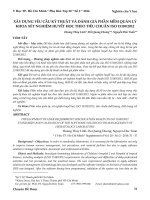
This test shall be performed to verify that a nozzle can safely withstand a drop of 2 m under –40 °C conditions.
Dimensions in metres
Key
1
Support
2
11 mm diameter fuelling hose
3
Nozzle
4
Concrete floor
Figure 1 — Test arrangement for dropping test
Following all drops described previously, the nozzle shall be capable of normal connection to the receptacle.
In addition, the nozzle shall comply with the leakage tests specified in 7.7 and 7.11 as well as the hydrostatic
strength test specified in 7.16.
7.7
Leakage at room temperature
These tests shall be performed to verify leakage rate of nozzle, receptacle, connector and receptacle check
valve at room temperature.
Tests shall be conducted at 0,5 MPa and 150 % of the nominal working pressure. All devices shall be checked
for leakage from the time of connection, through pressurization, to the time of disconnection.
To verify the leakage rate of the nozzle, the receptacle and the connector, pressurized leak test gas shall be
applied to the inlet of the connector, the disconnected nozzle and the outlet of the disconnected receptacle.
6
Copyright International Organization for Standardization
Provided by IHS under license with ISO
No reproduction or networking permitted without license from IHS
© ISO 2012 – All rights reserved
Licensee=University of Alberta/5966844001, User=sharabiani, shahramfs
Not for Resale, 12/02/2013 05:00:45 MST
--``,,,``,,`,```,,,,`,```,```,,,-`-`,,`,,`,`,,`---
A nozzle conditioned at –40 °C for 24 hours shall be connected to a 5 m length of the appropriately rated
fuelling hose, and then dropped 2 m onto a concrete floor as shown in Figure 1. The nozzle shall be dropped
ten times within five minutes of removal from the conditioning chamber, then pressurised to maximum working
pressure and subjected to ten additional drops within five further minutes.
ISO 17268:2012(E)
To verify the leakage rate of the receptacle check valve, pressurized leak test gas shall be applied to the inlet of
the connector. The upstream portion of the receptacle shall be quickly depressurized, the nozzle disconnected
and the receptacle check-valve checked for leakage.
Following the tests described above, the nozzle, receptacle, connector and receptacle check valve shall be
bubble free for 1 minute. If bubbles are detected then the leak rate shall be measured by either an external
vacuum test using leak test gas (global accumulation test) or an equivalent method to show that the leak rate
is less than 20 cm3/h of hydrogen at 20 °C.
NOTE
The permitted leakage rate is applicable to tests with 100 % hydrogen only. Permitted leakage rates for other
gases or gas mixtures are to be converted to an equivalent leakage rate to that for 100 % hydrogen.
7.8
Valve operating handle
This test shall be performed to verify that nozzles equipped with operating handles can withstand a maximum
force without damage.
A 200 N force shall be applied to the valve operating handle at the point furthest away from the axis of rotation
in both the opening and closing directions. The test shall be performed with the nozzle properly connected to
a receptacle, and with the nozzle intentionally, improperly engaged relative to the receptacle.
Following the tests, the nozzle shall maintain safe operating functionality.
7.9
Receptacle vibration resistance
This test shall be performed to verify receptacle and protective cap resistance to vibration.
The receptacle and protective cap shall be secured in a test apparatus and vibrated at each integer frequency
from 5 Hz to 60 Hz for eight minutes at each frequency. The amplitude of the vibration shall be at least 1,5 mm
from 5 Hz to 20 Hz, 1,2 mm from 20 Hz to 40 Hz, and 1 mm from 40 Hz to 60 Hz. The tests shall be conducted
once in the axial direction, and again in the radial direction.
Following the tests, there shall be no visible damage to the receptacle and protective caps. The receptacle
shall comply with all the receptacle leakage tests specified in 7.7 and 7.11 as well as the hydrostatic strength
test specified in 7.16.
7.10
Abnormal loads
This test shall be performed to verify that the nozzle and receptacle can withstand abnormal loads in service.
The connected nozzle and receptacle may be subjected to the following abnormal loads in service:
a)
pulls along the nozzle or receptacle longitudinal axis;
b)
moments applied to the end fitting of the nozzle.
The connected nozzle and receptacle shall be able to withstand abnormal loads of a = 1 000 N, b = 120 N•m
without distortion or damage.
Also, the connected nozzle and receptacle shall be able to withstand abnormal loads of a = 2000 N; b = 240 N•m
without leakage. The moment arm shall be measured from the point of attachment of the receptacle to the
vehicle body to the hose inlet of the nozzle.
The nozzle and receptacle test fixture shall be tested in the pressurized and non-pressurized condition. During
the pressurized test the nozzle and receptacle test fixture shall be pressurized to maximum working pressure.
The appropriate “Loose Fit” test fixture (see Annex C) shall be used for this test. The test fixture shall be
mounted as a cantilever to a supporting member. For the purposes of this test, the supporting member shall
be capable of withstanding the specified loads without displacement or deflection. The nozzle shall be properly
connected to the test fixture.
Following the tests, the nozzle and connector shall comply with the appropriate leakage tests specified in 7.7
and 7.11 as well as the hydrostatic strength test specified in 7.16.
7.11
7.11.1
Low and high temperatures
Purpose
--``,,,``,,`,```,,,,`,```,```,,,-`-`,,`,,`,`,,`---
7
© ISO 2012 – All rights reserved
Copyright International Organization for Standardization
Provided by IHS under license with ISO
No reproduction or networking permitted without license from IHS
Licensee=University of Alberta/5966844001, User=sharabiani, shahramfs
Not for Resale, 12/02/2013 05:00:45 MST
ISO 17268:2012(E)
These tests shall be performed to verify leakage rate and operation of nozzle, receptacle and connector at low
and high temperatures.
7.11.2
General
Prior to conditioning, the devices shall be purged with nitrogen and then sealed from atmosphere under a
pressure of 7 MPa leak test gas. All tests shall be conducted while the devices are continuing to be exposed to
the specified test temperatures. The outlet of the device shall be plugged and the test pressure shall be applied
to the inlet of the device.
Leakage tests
Fuelling connection devices shall be leak tested in accordance with the test conditions listed below after
2 hours of conditioning for the components and leak detector (if used):
a)
The nozzle and receptacle coupled, conditioned at −40 °C and pressurised at 0,5 MPa and maximum
working pressure.
b)
The nozzle and receptacle coupled, conditioned at 50 °C and pressurised at 1 MPa and maximum
working pressure.
c)
The receptacle uncoupled, conditioned at −40 °C and pressurised at 0,5 MPa and maximum working pressure.
d)
The receptacle uncoupled, conditioned at 85 °C and pressurised at 1 MPa and maximum working pressure.
e)
The nozzle uncoupled, conditioned at −40 °C and pressurised at 0,5 MPa and maximum working pressure.
f)
The nozzle uncoupled, conditioned at 50 °C and pressurised at 1 MPa and maximum working pressure.
Pressurised leak test gas shall be applied to the test components. The external body shall then be checked for
bubble tight leakage using
g)
at −40 °C, immersion in a 100 % denatured ethyl alcohol mixture for 1 min, and
h)
at 50 °C or 85 °C, immersion in 50 °C or 85 °C water for 1 min.
Following the tests, the nozzle, receptacle and connector shall be bubble free for 1 minute or have a leak rate
less than 20 cm3/h at 20 °C.
NOTE
The permitted leakage rate is applicable to tests with 100 % hydrogen only. Permitted leakage rates for other
gases or gas mixtures are to be converted to an equivalent leakage rate to that for 100 % hydrogen.
7.11.4
Operation tests
The devices shall function under the following conditions.
a)
The nozzle and receptacle connected and disconnected ten times when conditioned at −40 °C and
pressurised to maximum working pressure.
b)
The nozzle and receptacle connected and disconnected ten times when conditioned at 85 °C and
pressurised to maximum of working pressure.
Following the tests, the devices shall connect and disconnect normally and deliver gas.
7.12
7.12.1
Durability and maintainability
Purpose
These tests shall be performed to verify that the nozzle, receptacle, receptacle check valve and connector can
withstand durability cycling.
7.12.2
Nozzle durability test
During the following tests, all devices shall be maintained according to the manufacturer’s instructions.
Requirements for maintenance at cycles less than specified by the manufacturer shall be considered as noncompliant with this International Standard.
8
Copyright International Organization for Standardization
Provided by IHS under license with ISO
No reproduction or networking permitted without license from IHS
© ISO 2012 – All rights reserved
Licensee=University of Alberta/5966844001, User=sharabiani, shahramfs
Not for Resale, 12/02/2013 05:00:45 MST
--``,,,``,,`,```,,,,`,```,```,,,-`-`,,`,,`,`,,`---
7.11.3
ISO 17268:2012(E)
The nozzle shall be capable of withstanding 100 000 cycles. For the purpose of this test, one cycle of operation
for Type A, B and C nozzles shall consist of the following.
a)
Properly connecting the nozzle to the receptacle test fixture.
b)
Pressurizing the connector to maximum working pressure using leak test gas.
c)
Depressurizing the connector.
d)
Disconnecting the nozzle.
While disconnected the test fixture shall be rotated relative to the nozzle at random or equal degree increments
throughout this test.
The receptacle test fixture shall be replaced at 15 000 cycle intervals as specified in Table 1 below.
Table1—Testfixtureselectionfornozzledurabilitytests
Number of cycles
Figure
Geometry
0 - 15 000
Annex D
Tight fit
15 000 - 30 000
Annex D
Tight fit
30 000 - 45000
Annex C
Loose fit
45 000 - 60 000
Annex C
Loose fit
60 000 - 75 000
Annex D
Tight fit
75 000 - 90 000
Annex D
Tight fit
90 000 - 100 000
Annex C
Loose fit
At the end of the 100 000 cycles the nozzle locking mechanism shall be checked at the normal disconnect
pressure to ensure it is properly engaged on the receptacle.
At the end of the 100 000 cycles the nozzle shall comply with 7.5, 7.7, 7.11 and 7.15. The nozzle shall comply
with 7.7 when tested with the appropriate simulated wear pattern test fixture shown in Annex E, as applicable.
After 15 000 cycles, the worn receptacle test fixtures shall not be in excess of wear patterns shown in Annex E
as applicable and shall comply with 7.7.
7.12.3
Receptacle check valve durability test
The receptacle check valve shall be capable of withstanding 15 000 operational cycles. For the purposes of
this test, one cycle of operation shall consist of the following:
a)
Properly connecting the receptacle to the nozzle test fixture.
b)
Pressurizing the connector to nominal working pressure in 6 pulses using leak test gas.
c)
Depressurizing the connector by first venting the upstream side of the receptacle check valve and then
lowering the pressure on the downstream side of the receptacle check valve to between 0 and a maximum
of 0,5 MPa prior to the next cycle.
Following 15 000 cycles of operation, the receptacle check valve shall then be subjected to 24 hours of flow at
the inlet/outlet flow conditions that cause the most severe chatter.
Following the test, the receptacle check valve shall comply with the leakage tests specified in 7.7 and 7.11 as
well as the electrical resistance test as specified in 7.15.
7.12.4
Receptacle durability test
The receptacle shall be capable of withstanding 15 000 operational cycles. For the purposes of this test, one
cycle of operation shall consist of the following:
a)
Properly connecting the receptacle to the nozzle.
b)
Pressurizing the connector to maximum working pressure using leak test gas.
--``,,,``,,`,```,,,,`,```,```,,,-`-`,,`,,`,`,,`---
9
© ISO 2012 – All rights reserved
Copyright International Organization for Standardization
Provided by IHS under license with ISO
No reproduction or networking permitted without license from IHS
Licensee=University of Alberta/5966844001, User=sharabiani, shahramfs
Not for Resale, 12/02/2013 05:00:45 MST
c)
Holding maximum working pressure for 30 seconds, minimum.
d)
Depressurizing the nozzle.
e)
Disconnecting the nozzle.
f)
Depressurizing the receptacle.
Following the tests, the receptacle shall then comply with the leakage tests specified in 7.7 and 7.11 as well as
the electrical resistance test specified in 7.15.
7.12.5
Connected nozzle and receptacle durability test
A nozzle test fixture or a receptacle test fixture, as applicable, shall be connected to the device under test.
The outlet of the receptacle shall be open to atmospheric pressure. The supply port of the nozzle shall be
connected to a supply system which will supply sufficient leak test gas as required below.
Each nozzle and receptacle shall be cycled for 30 cycles. Each cycle shall consist of a total of the full flow
of gas with the supply pressure starting at nominal working pressure. A cycle shall be two seconds in length
and the supply pressure shall not fall below 80 % nominal working pressure at the end of each cycle. The test
supply system shall not limit the flow during this test.
Following the tests, the connected nozzle and receptacle shall then comply with the leakage tests specified in 7.7.
7.13
7.13.1
Sealing material aging test
Purpose
These tests shall be performed to verify sealing material resistance to aging.
7.13.2
Oxygen aging test procedure
Sealing materials shall be listed and rated by the manufacturer as being resistant to oxygen aging. Samples
of synthetic material parts shall be subjected to 96 hours of exposure at 70 °C and at 2 MPa. This test shall be
conducted in accordance with ISO 188.
Following the tests, synthetic material parts of fuelling connection devices shall not crack or show visible
evidence of deterioration.
7.13.3
Ozone aging test procedure
Sealing materials exposed to the atmosphere without the continuous presence of internal gas pressure (e.g.
receptacle face seal O-ring) shall be listed and rated by the manufacturer as being resistant to ozone aging.
Samples of synthetic material parts shall be stressed to 20 % elongation and exposed for a period of 120 hours to
air at 40 °C with a volume fraction of ozone of 5 x 10 -7. This test shall be conducted in accordance with ISO 1431-1.
Following the tests, synthetic material parts of fuelling connection devices shall not crack or show visible
evidence of deterioration.
7.14
Non-metallic material hydrogen resistance test
This test shall be performed to verify wetted non-metallic material resistance to hydrogen.
Representative sample(s) of wetted non-metallic material shall be prepared, measured and weighed. The
samples shall then be immersed in hydrogen at nominal working pressure for 168 hours at 20 °C ± 5 °C.
Following this time period, the test pressure shall be reduced to atmospheric pressure in less time than the
seals would have to depressurise in actual service, not to exceed 1 second.
Following the tests, the test samples shall not exhibit evidence of explosive decompression damage. In addition, the
samples shall not swell more than 25 %, shrink more than one percent and incur a weight loss in excess of 10 %.
7.15
Electrical resistance
This test shall be performed to verify the electrical resistance of the connector.
The electrical resistance of the connector shall be measured.
The electrical resistance of the connected receptacle and nozzle shall not be greater than 1000 ohms either in
the pressurised or unpressurised state.
7.16
10
Hydrostatic strength
Copyright International Organization for Standardization
Provided by IHS under license with ISO
No reproduction or networking permitted without license from IHS
© ISO 2012 – All rights reserved
Licensee=University of Alberta/5966844001, User=sharabiani, shahramfs
Not for Resale, 12/02/2013 05:00:45 MST
--``,,,``,,`,```,,,,`,```,```,,,-`-`,,`,,`,`,,`---
ISO 17268:2012(E)
ISO 17268:2012(E)
These tests shall be performed to verify the hydrostatic strength of the nozzle, receptacle and connector.
Because the hydrostatic strength test is a terminal test, the test samples shall not be used for any other
subsequent testing.
Outlet openings of the uncoupled nozzle, the uncoupled receptacle and the connector shall be plugged and
valve seats or internal blocks made to assume the open position. A hydrostatic pressure of 3 times maximum
working pressure shall be applied to the nozzle, to the receptacle as well as the connector for a period of at
least three minutes.
During the test, then uncoupled nozzle, the uncoupled receptacle and the connector shall not leak.
7.17
7.17.1
Corrosion resistance
Purpose
These tests shall be performed to verify nozzle and receptacle resistance to corrosion.
7.17.2
General
New samples shall be used. Protective caps shall be in place. Vent holes in the protective caps shall not be
plugged. Process connections may be plugged.
7.17.3
Nozzle test
The nozzle and the receptacle shall be supported in a horizontal position. The nozzle shall be exposed for
96 hours to a salt spray as specified in ISO 9227.
Throughout the test, the temperature within the test chamber shall be maintained between 33 °C and 36 °C.
The salt spray solution shall consist of a mass fraction of 5 % of sodium chloride and 95 % distilled water.
A pressure of 0,5 MPa of air shall also be continuously applied to the inlet of the nozzle. The nozzle shall be
operated once an hour to dispense air (to the atmosphere through a dummy receptacle) during the first eight
hour test period.
Immediately following the 96 hour test the nozzle shall be rinsed and gently cleaned of salt deposits.
The nozzle shall not show evidence of corrosion or loss of protective coatings and shall comply with the
leakage tests specified in 7.7.
7.17.4
Receptacle test
The receptacle shall be supported in a horizontal position and shall be exposed for 1 000 hours to a salt spray
as specified in ISO 9227. Throughout the test, the temperature within the test chamber shall be maintained
between 33 °C and 36 °C. The salt spray solution shall consist of a mass fraction of 5 % sodium chloride and
95 % distilled water.
Immediately following the 1 000 hour test, the areas of receptacles protected by dust caps shall be examined.
The receptacle shall then be rinsed and gently cleaned of salt deposits.
The receptacle shall not show evidence of corrosion or loss of protective coatings and there shall be no
evidence that water has entered the area protected by dust caps. The receptacle shall then comply with the
leakage tests specified in 7.7.
7.18
Deformation
This test shall be performed to verify that field connected/assembled parts can withstand a specified
installation over-torque.
The nozzle and the receptacle shall be connected and assembled to 150 % of the manufacturer’s assembly torque.
While still connected and assembled, the connector shall comply with the leakage tests specified in 7.7 and the
hydrostatic strength test specified in 7.16.
7.19
Contamination test
This test shall be performed to verify that the nozzle and receptacle can withstand contamination.
A tank or vessel shall be filled to a depth of 100 mm ± 5 mm with a solution/suspension having a volume
fraction of 5 % salt and sand complying to A4 coarse grade of test dust of ISO 12103-1, or the equivalent
11
© ISO 2012 – All rights reserved
--``,,,``,,`,``
Copyright International Organization for Standardization
Provided by IHS under license with ISO
No reproduction or networking permitted without license from IHS
Licensee=University of Alberta/5966844001, User=sharabiani, shahramfs
Not for Resale, 12/02/2013 05:00:45 MST
ISO 17268:2012(E)
dissolved/suspended in distilled water. The connection end of the nozzle and receptacle shall be dipped into
the solution/suspension for one to five seconds and removed. The nozzle and receptacle shall be dipped in a
manner that the entire connection area is submerged without touching the bottom.
After dipping both the nozzle and receptacle in the solution/suspension, the receptacle and nozzle shall be
connected. The coupled pair shall have leak test gas at the maximum working pressure blown through for 5 s
for 10 consecutive cycles. The nozzle and receptacle shall not be cleaned during the test.
The connector shall be subjected to the leakage test specified in 7.7 after each cycle.
7.20
Thermal cycle test
This test shall be performed to verify that the nozzle and receptacle can withstand thermal cycling.
The nozzle, receptacle, and a connector shall be pressurized to the nominal working pressure. The components
shall be subjected to an external temperature of 85 °C within one half hour, and soaked at that temperature for
2 hours. The components shall then be subjected to an external temperature of −40 °C in less than one hour
and soaked at that temperature for 2 hours. Finally, the external temperature shall be returned to 15 °C within
one half hour to complete the cycle. This cycle shall be repeated 100 times.
The nozzle, receptacle and connector shall comply with the leakage tests specified in 7.7 and 7.11 as well as
the hydrostatic strength test specified in 7.16.
7.21
Pre-cooled hydrogen exposure test
This test shall be performed to verify that the nozzle and receptacle can withstand exposure to pre-cooled
hydrogen during fuelling.
The connector shall be subjected to pre-cooled hydrogen gas at −40 °C at a flow rate of 30 g/s at 15 °C and
90 % relative humidity for a minimum of 3 minutes. The nozzle shall be depressurized, then disconnected
within 10 seconds and re-connected to another dry receptacle after a two minute hold period. This test shall
be repeated 10 times.
This test procedure shall be repeated for an additional ten cycles, except that the hold period shall be increased
to 15 minutes.
The nozzle, receptacles and connector shall comply with the leakage tests specified in 7.7 and 7.11. Failure to
disconnect the nozzle within 10 seconds shall constitute failure of the test.
7.22
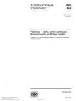
Misconnected nozzle test
This test shall be performed to verify that a misconnected nozzle shall not flow gas.
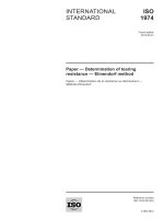
A series of thin shims as shown in Figure 2 shall be inserted in the space between the nozzle and the stop ring
of the receptacle to create a misconnected condition. If it is not possible to manufacture a shim small enough
to create a misconnected condition, the receptacle stop ring position shall be adjusted to accommodate the
shim (see Figure 3).
The connector shall be subjected to 10 MPa leak test gas for 1 minute.
The test shall be repeated with the use of 90 degree arc shims.
Figure 2 — Use of shims to create a misconnected connector
12
Copyright International Organization for Standardization
Provided by IHS under license with ISO
No reproduction or networking permitted without license from IHS
--``,,,``,,`,```,,,,`,```,```,,,-`-`,,`,,`,`,,`---
© ISO 2012 – All rights reserved
Licensee=University of Alberta/5966844001, User=sharabiani, shahramfs
Not for Resale, 12/02/2013 05:00:45 MST
ISO 17268:2012(E)
Key
1
Adjustment depth
a
30 mm for 35 MPa and 40 mm for 70 MPa
Figure 3 — Adjustment of stop ring position to accommodate a shim
The nozzle shall not flow gas in the misconnected state.
7.23
Upward/downward nozzle compatibility test
This test shall be performed to verify that a nozzle shall connect to a receptacle rated to a higher nominal working
pressure, and to verify that a nozzle shall not connect to a receptacle rated to a lower nominal working pressure.
7.23.1
Upwards nozzle compatibility test
The nozzle shall be connected to representative receptacles rated to a higher nominal working pressure and
pressurized with leak test gas.
The connector shall comply with the leakage tests specified in 7.7.
7.23.2
Downwards nozzle compatibility test
Attempts shall be made to connect the nozzle to representative receptacles of maximum length tolerance rated
to a lower nominal working pressure.
The nozzle shall not connect to representative receptacles rated to a lower nominal working pressure.
7.24
Washout test
This test shall be performed to verify that the main internal O-ring seal of an H70 receptacle does not washout
when connected with a nozzle rated to a lower nominal working pressure.
The connector shall be subjected to hydrogen gas at a flow rate of 65 g/s (+2 g/s) and at maximum working
pressure for a minimum of 10 seconds. This test shall be repeated 10 times with a delay of at least 5 seconds
between bursts.
The test shall be conducted at temperatures of -40°C (+ 5°C) and 85°C (+ 5°C) with the unpressurized connector
preconditioned for 30 minutes at the test temperature.
There shall be no displacement of the internal O-ring seal(s) after the test. The receptacle shall then comply
with the leakage tests specified in 7.7 and 7.11.
8 Instructions
Manufacturers of receptacles and nozzles shall provide clear and concise printed instructions and diagrams in
a form that can be easily understood and are adequate for
a)
proper field assembly,
b)
installation,
c)
safe operation by all users,
© ISO 2012 – All rights reserved
Copyright International Organization for Standardization
Provided by IHS under license with ISO
No reproduction or networking permitted without license from IHS
--``,,,``,,`,```,,,,`,```,```,,,-`-`,,`,,`,`,,`---
Licensee=University of Alberta/5966844001, User=sharabiani, shahramfs
Not for Resale, 12/02/2013 05:00:45 MST
13
ISO 17268:2012(E)
d)
suitability and use, and
e)
transport, storage and handling.
Special tools required for connection of receptacles to tubing shall be clearly identified in the instructions.
In addition, the manufacturer shall provide clear instructions on the required maintenance and required periodic
inspection of components as well as the expected service life of the receptacle and nozzle including the
expected service life of components, if different.
9 Marking
Markings required by this Clause shall be in a legible and easily understandable form. These markings shall
be embossed, cast, low stress stamped or otherwise formed in the part or a permanently attached plate. This
includes markings baked into an enamelled surface. Permanently attached marking plates shall be securely
attached by mechanical means. All markings shall be at least 2,5 mm high.
Nozzles and receptacles shall bear the following information:
a)
The manufacturer’s or dealer’s name, trademark or symbol;
b)
The model designation;
c)
The appropriate standard designation, H11, H25, H35, H35HF or H70;
d)
The applicable Type A, B or C (Nozzles only);
e)
In the case of Type A nozzle, the direction of the ON and OFF operation of the actuating mechanism;
f)
Marking for traceability of receptacles in suitable lots. Nozzles shall carry individual serial numbers.
A reference to this International Standard, ISO 17268:2012.
14
Copyright International Organization for Standardization
Provided by IHS under license with ISO
No reproduction or networking permitted without license from IHS
--``,,,``,,`,```,,,,`,```,```,,,-`-`,,`,,`,`,,`---
© ISO 2012 – All rights reserved
Licensee=University of Alberta/5966844001, User=sharabiani, shahramfs
Not for Resale, 12/02/2013 05:00:45 MST
ISO 17268:2012(E)
Annex A
(normative)
Receptacle/nozzle interface envelope
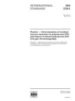
Dimensions in millimetres
NOTE
a
Depending on the vehicle design, the overall depth of the fuelling cavity need not be as large as indicated here.
Minimum length of the receptacle that shall be clear of provisions for attachment of receptacle or protective cap.
b For minimum coupling clearance only. System designers shall ensure that the dust or protective cap operates freely
in the provided space.
Figure A.1 — Receptacle/nozzle interface envelope
--``,,,``,,`,```,,,,`,```,```,,,-`-`,,`,,`,`
15
© ISO 2012 – All rights reserved
Copyright International Organization for Standardization
Provided by IHS under license with ISO
No reproduction or networking permitted without license from IHS
Licensee=University of Alberta/5966844001, User=sharabiani, shahramfs
Not for Resale, 12/02/2013 05:00:45 MST
ISO 17268:2012(E)
Annex B
(normative)
Hydrogen Receptacles
Dimensions in millimetres
Material shall demonstrate hydrogen compatibility as described in 4.5 and a minimum hardness of 80 Rockwell
B (HRB). Unless otherwise specified, surface finish shall be 0,4 µm to 3,2 µm.
a Shaded area represents an area, which shall be kept free of all components except for the seal. Surface finish shall
be 0,8 µm ± 0,05 µm.
b Reference sealing material surface to a no. 110 O-Ring with the following dimensions: internal diameter: 9,19 mm ±
0,13 mm; width: 2,62 mm ± 0,08 mm.
c
Nozzle side: No part of the nozzle assembly shall extend beyond the receptacle stop ring.
d Vehicle side: The stop ring shall have a continuous shape that has an effective diameter of 30 mm or more and a
thickness greater than 5 mm.
Figure B.1 — H11 Hydrogen Receptacle
16
Copyright International Organization for Standardization
Provided by IHS under license with ISO
No reproduction or networking permitted without license from IHS
--``,,,``,,`,```,,,,`,```,```,,,-`-`,,`,,`,`,,`---
© ISO 2012 – All rights reserved
Licensee=University of Alberta/5966844001, User=sharabiani, shahramfs
Not for Resale, 12/02/2013 05:00:45 MST