Bsi bs au 169a 1992 (1999) iso 3795 1989
Bạn đang xem bản rút gọn của tài liệu. Xem và tải ngay bản đầy đủ của tài liệu tại đây (423.3 KB, 14 trang )
BRITIS H S TAND ARD
BS AU 1 69a:
1 992
IS O 3 795 : 1 989
NM — 14A
12 pages
Method for
D etermination of
b urning b ehaviour of
interior materials for
road vehicles, and
tractors and machinery
for agriculture and
forestry
BS AU 169a:1992
Committees responsible for this
British Standard
The preparation of this British Standard was entrusted by the Automobile
Standards Policy Committee (AUE/- ) to Technical Committee AUE/1 5, upon
which the following bodies were represented:
Association of Trailer Manufacturers
Caravan Club
Department of Transport
Metropolitan Police
Motor Industry Research Association
National Caravan Council Limited
Society of Motor Manufacturers and Traders Limited
This British Standard, having
been prepared under the
direction of the Automobile
Standards Policy Committee,
was published under the
authority of the Standards
Board and comes into effect on
1 May 1 992
© BSI 03- 1 999
First published December 1 978
Second edition May 1 992
The following BSI references
relate to the work on this
standard:
Committee reference AUE/1 5
Draft for comment 87/70299 DC
ISBN 0 580 20825 7
Amendments issued since publication
Amd. No.
Date
Comments
BS AU 169a:1992
Contents
Page
Committees responsible
Inside front cover
National foreword
ii
1
Scope
1
2
Normative reference
1
3
Definitions
1
4
Principle
1
5
Apparatus
1
6
Samples
5
7
Procedure
6
8
Calculation
7
9
Test report
7
Figure 1 — Example of combustion chamber with sample holder
and drip pan
2
Figure 2 — Example of combustion chamber
3
Figure 3 — Typical drip pan
3
Figure 4 — Example of sample holder
4
Figure 5 — Example of section of lower U- frame design for wire
support facility
5
Figure 6 — Sample
6
Publication(s) referred to
© BSI 03- 1 999
Inside back cover
i
BS AU 1 69a:1 992
National foreword
This British Standard has been prepared under the direction of the Automobile
Standards Policy Committee and is identical with ISO 3795: 1 989 “Road
v ehicles,
and tractors and m achinery fo r agriculture and fores try — Determ ination of
b urning b ehav iour o f interior m aterials
”, published by the international
Organization for Standardization (ISO) .
This revision of this standard supersedes BS AU 1 69: 1 978 which is withdrawn.
The revision comprises extension of the title and scope to cover tractors and
machinery for agriculture and forestry. The technical content of the standard
remains unaltered.
Cross-reference . The Technical Committee has reviewed the provisions of
ISO 2768- 1 : 1 989, to which normative reference is made in the text, and has
decided that they are acceptable for use in conj unction with this standard.
A British Standard does not purport to include all the necessary provisions of a
contract. Users of British Standards are responsible for their correct application.
Compliance with a British Standard does not of itself confer immunity
from legal obligations.
Summary of pages
This document comprises a front cover, an inside front cover, pages i and ii,
pages 1 to 8, an inside back cover and a back cover.
This standard has been updated (see copyright date) and may have had
amendments incorporated. This will be indicated in the amendment table on
the inside front cover.
ii
© BSI 03- 1 999
ISO 3795:1 989 (E)
1 Scope
when different materials are connected together
This International Standard specifies a method for
determining the horizontal burning rate of
materials used in the occupant compartment of road
vehicles (for example, passenger cars, lorries/trucks,
estate cars, coaches), and of tractors and machinery
for agriculture and forestry, after exposure to a
intermittently (for example, by sewing,
high- frequency welding, riveting) , then in order to
permit the preparation of individual samples in
accordance with clause 6 , such materials will not be
considered as composite materials
3.3
small flame.
exposed side
This method permits testing of materials and parts
side which faces towards the occupant compartment
of the vehicle interior equipment individually or in
when the material is mounted in the vehicle
combination up to a thickness of 1 3 mm. It is used to
j udge the uniformity of production lots of such
materials with respect to their burning behaviour.
4 Principle
A sample is held horizontally in a U- shaped holder
Because of the many differences between the real
and is exposed to the action of a defined low- energy
world situation (application and orientation within
flame for 1 5 s in a combustion chamber, the flame
vehicle interior, conditions of use, ignition source,
acting on the free end of the sample. The test
etc. ) and the precise test conditions specified in this
determines if and when the flame extinguishes or
International Standard, this method cannot be
the time in which the flame passes a measured
considered as suitable for evaluation of all true
distance.
in- vehicle burning characteristics.
2 Normative reference
5 Apparatus
5.1
Com b ustion cham b er
(see Figure 1 ), preferably
The following standard contains provisions which,
of stainless steel and having the dimensions given
through reference in this text, constitute provisions
in Figure 2. The front of the chamber contains a
of this International Standard. At the time of
flame- resistant observation window, which may
publication, the edition indicated was valid. All
cover the front and which can be constructed as an
standards are subj ect to revision, and parties to
access panel.
agreements based on this International Standard
are encouraged to investigate the possibility of
applying the most recent edition of the standard
indicated below. Members of IEC and ISO maintain
registers of currently valid International Standards.
ISO 2768- 1 : 1 989,
General tolerances —
The bottom of the chamber has vent holes, and the
top has a vent slot all around. The combustion
chamber is placed on four feet, 1 0 mm high.
The chamber may have a hole at one end for the
introduction of the sample holder containing the
sample; in the opposite end, a hole is provided for
Part 1 : Tolerances for linear and angular
the gas line. Melted material is caught in a pan
dim ensions w itho ut indiv idual to lerance
(see Figure 3) which is placed on the bottom of the
indicatio ns.
3 Definitions
chamber between vent holes without covering any
vent hole area.
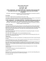
5.2
Sam p le holder,
consisting of two U- shaped metal
For the purposes of this International Standard, the
plates or frames of corrosion- proof material.
following definitions apply.
Dimensions are given in Figure 4.
3.1
The lower plate is equipped with pins, the upper one
burning rate
with corresponding holes in order to ensure
quotient of the burnt distance measured according
to this International Standard and the time taken to
burn this distance
it is expressed in millimetres per minute
3.2
composite material
consistent holding of the sample. The pins also serve
as the measuring points at the beginning and end of
the burning distance.
A support shall be provided in the form of 0, 25 mm
diameter heat- resistant wires spanning the frame
at 25 mm intervals over the bottom U- shaped frame
(see Figure 5).
material composed of several layers of similar or
different materials intimately held together at their
surfaces by cementing, bonding, cladding, welding,
etc.
© BSI 03- 1 999
1
ISO 3795:1 989 (E)
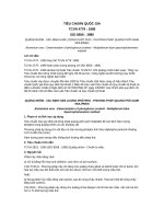
Figure 1 — Example of combustion chamber with sample holder and drip pan
2
© BSI 03 - 1 999
ISO 3795:1 989 (E)
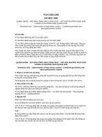
Figure 2 — Example of combustion chamber
Figure 3 — Typical drip pan
© BSI 03- 1 999
3
ISO 3795:1 989 (E)
The plane of the lower side of samples shall
5.3
be 1 78 mm above the floor plate. The distance of the
provided by a Bunsen burner having an inside
Gas b urner.
The small ignition source is
front edge of the sample holder from the end of the
diameter of 9, 5 mm. It is located in the test cabinet
chamber shall be 22 mm; the distance of the
so that the centre of its nozzle is 1 9 mm below the
longitudinal sides of the sample holder from the
centre of the bottom edge of the open end of the
sides of the chamber shall be 50 mm (all inside
sample (see Figure 2).
dimensions) . (See Figure 1 and Figure 2. )
5.4
Tes t gas
. The gas supplied to the burner shall
have a calorific value of approximately 38 MJ/m
3
(for example natural gas).
Figure 4 — Example of sample holder
4
© BSI 03- 1 999
ISO 3795:1 989 (E)
Figure 5 — Example of section of lower U-frame design for wire support facility
5.5
Metal comb , at least 1 1 0 mm in length, with
When the shape and dimensions of a product do not
seven to eight smooth rounded teeth per 25 mm.
permit taking a sample of the given size, the
5.6
Stop- watch , accurate to 0, 5 s.
following minimum dimensions shall be
5.7
Fume cupboard. The combustion chamber may
be placed in a fume cupboard assembly provided
maintained:
a) For samples having a width of 3 mm to 60 mm,
that the internal volume is at least 20 times, but not
the length shall be 356 mm. In this case, the
more than 1 1 0 times, greater than the volume of the
material is tested in the product width.
combustion chamber and provided that no single
b) For samples having a width of 60 mm
height, width, or length dimension of the fume
to 1 00 mm, the length shall be at least 1 38 mm.
cupboard is greater than 2, 5 times either of the
In this case the potential burning distance
other two dimensions.
corresponds to the length of the sample, the
Before the test, the vertical velocity of the air
measurement starting at the first measuring
through the fume cupboard shall be
point.
measured 1 00 mm in front of and behind the final
c) Samples having a width of less than 60 mm
position where the combustion chamber will be
and shorter than 356 mm, and samples having a
located. It shall be between 0, 1 m/s and 0, 3 m/s in
width of 60 mm to 1 00 mm and shorter
order to avoid possible discomfort, by combustion
than 1 38 mm, cannot be tested according to this
products, to the operator. It is possible to use a fume
method; neither can samples having a width less
cupboard with natural ventilation and an
than 3 mm.
appropriate air velocity.
6 Samples
6.1 Shape and dimensions
6.2 Sampling
At least five samples shall be taken from the
material under test. In materials having different
burning rates in different material directions
The shape and dimensions of samples are given
(preliminary tests will show this), the five (or more)
in Figure 6. The thickness of the sample
samples are to be taken and placed in the test
corresponds to the thickness of the product to be
apparatus so that the highest burning rate will be
tested. It shall not be more than 1 3 mm. When
measured.
taking the sample permits, the sample shall have a
constant section over its entire length.
© BSI 03- 1 999
5
ISO 3795:1 989 (E)
Figure 6 — Sample
When the material is supplied in widths, a length of
at least 500 mm shall be cut covering the entire
width. From this, the samples shall be taken so as to
be at least 100 mm from the material edge and
equidistant from each other.
Samples shall be taken in the same way from
finished products, when the shape of the product
permits. When the thickness of the product
is 13 mm or more, it shall be reduced to 13 mm by a
mechanical process applied to the side which does
not face the occupant compartment.
Composite materials (see 3.2 ) shall be tested as if
they were of uniform construction.
In the case of materials made of superimposed
layers of different composition which are not
composite materials, all the layers of material
included within a depth of 13 mm from the surface
facing towards the occupant compartment shall be
tested individually.
7.3 Adjust the gas flame to a height of 38 mm using
the mark in the chamber, the air intake of the
burner (5.3 ) being closed. Before starting the first
test, the flame shall burn at least for 1 min for
stabilization.
7.4 Push the sample holder (5.2 ) into the
combustion chamber (5.1 ) so that the end of the
sample is exposed to the flame, and after 15 s cut off
the gas flow.
7.5 The measurement of the burning time starts at
the moment when the foot of the flame passes the
first measuring point. Observe the flame
propagation on the side burning faster than the
other (upper or lower side).
7.6 Measurement of burning time is completed
when the flame has come to the last measuring
point or when the flame extinguishes before coming
to the last measuring point. If the flame does not
reach the last measuring point, measure the burnt
distance up to the point where the flame
6.3 Conditioning
extinguished. Burnt distance is the decomposed
The samples shall be conditioned for at least 24 h part of the sample, which is destroyed on its surface
but not more than 7 days at a temperature
or in the interior by burning.
of 23 °C ± 2 °C and a relative humidity
Insofar as the sample does not ignite or does not
of 50 % ± 5 % and shall be maintained under these 7.7
continue
burning after the burner has been
conditions until immediately prior to testing.
extinguished, or when the flame extinguishes before
reaching the first measuring point, so that no
7 Procedure
burning time is measured, note in the test report
7.1 Place samples with napped or tufted surfaces on
that the burning rate is 0 mm/min.
a flat surface and comb twice against the nap using 7.8 When running a series of tests or repeat tests,
the comb (5.5 ).
ensure that the combustion chamber and sample
7.2 Place the sample in the sample holder (5.2 ) so
holder have a maximum temperature of 30 °C
that the exposed side will be downwards to the
before starting the next test.
flame.
6
© BSI 03-1999
ISO 3795:1 989 (E)
8 Calculation
The burning rate,
d) preparation of the sample, including the
B, in millimetres per minute, is
given by the formula
B
=
transverse) ;
f) number of samples tested:
g) test results:
is the burnt distance, in millimetres;
is the time, in seconds, to burn distance
greater than 1 3 mm) according to 6.2 ;
e) position of sample in the product (lengthwise,
s-- × 60
t
where
s
t
method of reducing the thickness (if thickness is
s.
— burnt distance, in millimetres, and burning
time, in seconds;
— other observations (self- extinguishing, etc. );
9 Test report
The test report shall include the following
particulars:
a) type, marking and colour of the test sample;
b) whether the sample was a composite or a single
material;
c) dimensions of the sample, including maximum
h) all calculated single values of burning rate, in
millimetres per minute;
i) special test conditions (use of fume cupboard,
use of ventilator, etc. );
j ) any conditions different from those specified in
this International Standard;
k) date of test.
and minimum values of thickness;
© BSI 03- 1 999
7
8
blank
BS AU 1 69a:1 992
Publication(s) referred to
See national foreword.
© BSI 03- 1 999
|
|
|
|
|
|
|
|
|
BSI Ð British Standards Institution
|
|
|
|
|
|
|
BSI is the independent national body responsible for preparing British Standards. It
|
|
|
|
|
|
|
presents the UK view on standards in E urope and at the international level. It is
incorporated by Royal Charter.
Revisions
|
|
|
|
British Standards are updated by amendment or revision. Users of British Standards
should make sure that they possess the latest amendments or editions.
|
|
|
It is the constant aim of BSI to improve the quality of our products and services. We
|
|
|
|
|
|
|
|
would be grateful if anyone finding an inaccuracy or ambiguity while using this
British Standard would inform the Secretary of the technical committee responsible,
the identity of which can be found on the inside front cover. Tel: 02 0 8996 9000.
Fax: 02 0 8996 7400.
|
|
BSI offers members an individual updating service called PLUS which ensures that
|
|
|
|
|
|
|
|
|
|
subscribers automatically receive the latest editions of standards.
Buying standards
Orders for all BSI, international and foreign standards publications should be
addressed to Customer Services. Tel: 02 0 8996 9001 . Fax: 02 0 8996 7001 .
|
|
|
|
In response to orders for international standards, it is BSI policy to supply the BSI
implementation of those that have been published as British Standards, unless
|
|
|
|
|
|
otherwise requested.
Information on standards
|
|
|
|
|
|
|
|
|
BSI provides a wide range of information on national, E urop ean and international
standards through its Library and its Technical Help to E xporters Service. Various
BSI electronic information services are also available which give details on all its
products and services. Contact the Information C entre. Tel: 02 0 8996 71 1 1 .
Fax: 02 0 8996 7048.
|
|
|
Subscribing members of BSI are kept up to date with standards developments and
|
|
|
|
|
|
|
|
|
receive substantial discounts on the purchase price of standards. For details of
these and other benefits contact Membership Administration. Tel: 020 8996 7002.
Fax: 02 0 8996 7001 .
Copyright
|
|
Copyright subsists in all BSI publications. BSI also holds the copyright, in the UK, of
|
|
the publications of the international standardization bodies. E xcept as permitted
|
|
|
|
|
|
under the C opyright, D esigns and Patents Act 1 988 no extract may be reproduced,
stored in a retrieval system or transmitted in any form or by any means ± electronic,
photocop ying, recording or otherwise ± without p rior written permission from BSI.
|
|
|
|
This does not preclude the free use, in the course of implementing the standard, of
necessary details such as symbols, and size, type or grade designations. If these
|
|
details are to be used for any other purpose than implementation then the prior
|
|
written permission of BSI must be obtained.
|
|
|
|
|
|
|
|
|
|
|
|
|
|
|
BSI
|
|
389 C hiswick High Road
|
|
London
|
|
W4 4AL
|
|
|
|
|
|
|
If permission is granted, the terms may include royalty payments or a licensing
agreement. Details and advice can be obtained from the Copyright Manager.
Tel: 02 0 8996 7070.