Bsi bs au 050 4 3 1a 1998 (iso 4250 3 1997)
Bạn đang xem bản rút gọn của tài liệu. Xem và tải ngay bản đầy đủ của tài liệu tại đây (688.09 KB, 18 trang )
BRITISH STANDARD AUTOMOBILE SERIES
BS AU
50-4-3.1 a:
1 998
ISO 425 0-3:
1 997
Tyres and wheels —
Part 4: Rim profiles and dimensions —
Section 3: Off-the-road rims —
Subsection 3.1 a Specification for
narrow and wide base off-the-road
vehicle rims
IC S 43 . 0 40 . 5 0
Reprodu ced by I H S u n d er l i cen se wi th BSI - U n con trol l ed Copy
BS AU 5 0-4-3.1 a:1 998
National foreword
This British Standard reproduces verbatim ISO 4250- 3: 1 997 and implements
it as the UK national standard. It supersedes BS AU 50- 4- 3. 1 : 1 991 , which is
withdrawn.
The UK participation in its preparation was entrusted to Technical Committee
AUE/4, Tyres and wheels for motor vehicles, which has the responsibility to:
— aid enquirers to understand the text;
— present to the responsible international/European committee any
enquiries on the interpretation, or proposals for change, and keep the UK
interests informed;
— monitor related international and European developments and
promulgate them in the UK.
A list of organizations represented on this committee can be obtained on
request to its secretary.
Cross-references
The British Standards which implement international or European
publications referred to in this document may be found in the BSI Standards
Catalogue under the section entitled “International Standards Correspondence
Index”, or by using the “Find” facility of the BSI Standards Electronic
Catalogue.
A British Standard does not purport to include all the necessary provisions of
a contract. Users of British Standards are responsible for their correct
application.
Compliance with a British Standard does not of itself confer immunity
from legal obligations.
Summary of pages
This document comprises a front cover, an inside front cover, pages i and ii,
the ISO title page, page ii, pages 1 to 1 1 and a back cover.
This standard has been updated (see copyright date) and may have had
amendments incorporated. This will be indicated in the amendment table on
the inside front cover.
This British Standard, having
been prepared under the
direction of the Engineering
Sector Board, was published
under the authority of the
Standards Board and comes
into effect on
1 5 January 1 998
© BSI 04- 1 999
ISBN 0 5 80 2941 8 8
Reprodu ced by I H S u n d er l i cen se wi th BSI - U n con trol l ed Copy
Amendments issued since publication
Amd. No.
Date
Comments
BS AU 5 0-4-3.1 a:1 998
Contents
Page
National foreword
Foreword
Inside front cover
ii
1
Scope
1
2
Rim identification
1
3
Rim contours
1
4
Rim knurling
1
5
Rim load and inflation pressures
1
6
Rim dimensions
1
Annex A (informative) Sealing ring grooves and O- rings for
earth- mover rims
© BSI 04- 1 999
Reprodu ced by I H S u n d er l i cen se wi th BSI - U n con trol l ed Copy
10
Figure 1 — Contours of 5° full tapered bead seat rims
2
Figure 2 — Contours of 5° full tapered bead seat rims
4
Figure 3 — Contours of semi- drop- centre rims
5
Figure 4 — Contours of 1 5° drop- centre rims
6
Figure 5 — Contours of 5° drop- centre rims
7
Figure 6 — Transverse knurling details
8
Table 1 — Contours of 5° full tapered bead seat rims
3
Table 2 — Contours of 5° full tapered bead seat rims
4
Table 3 — Contours of semi- drop- centre rims
5
Table 4 — Contours of 1 5° drop- centre rims
6
Table 5 — Contours of 5° drop- centre rims
7
Table 6 — Knurling widths for rim
8
Table 7 — Earth- mover specified rim diameters
9
i
ii
Reprodu ced by I H S u n d er l i cen se wi th BSI - U n con trol l ed Copy
blank
Reprodu ced by I H S u n d er l i cen se wi th BSI - U n con trol l ed Copy
BS AU 5 0-4-3.1 a:1 998
Foreword
ISO (the International Organization for Standardization) is a worldwide
federation of national standards bodies (ISO member bodies). The work of
preparing International Standards is normally carried out through ISO technical
committees. Each member body interested in a subject for which a technical
committee has been established has the right to be represented on that committee.
International organizations, governmental and non-governmental, in liaison with
ISO, also take part in the work. ISO collaborates closely with the International
Electrotechnical Commission (IEC) on all matters of electrotechnical
standardization.
Draft International Standards adopted by the technical committees are circulated
to the member bodies for voting. Publication as an International Standard requires
approval by at least 75 % of the member bodies casting a vote.
International Standard ISO 4250-3 was prepared by Technical Committee
ISO/TC 31,
Subcommittee SC 6,
Tyres,
rim s and v alv es,
Off- the- road tyres and
rim s.
This second edition cancels and replaces the first edition (ISO 4250-3:1987), of
which it constitutes a technical revision.
ISO 4250 consists of the following parts, under the general title
Earth- m ov er tyres
and rim s:
—
—
—
Annex A of this part of ISO 4250 is for information only.
Part 1 : Tyres des ignations and dim ensions;
Part 2: Lo ads and inflatio n p res sures;
Part 3: Rim s.
Descriptors:
designation.
Site equipment, self-propelled machines, earth-moving equipment, rims, dimensions,
ii
Reprodu ced by I H S u n d er l i cen se wi th BSI - U n con trol l ed Copy
© BSI 04-1999
BS AU 50-4-3.1 a:1 998
Loose flanges shall be marked on an externally
1 Scope
ISO 4250 consists of three parts (see the Foreword)
laying down the technical elements relating to
designation and dimensions of tyres and rims for
earth- moving machinery: it also gives load tables for
visible surface. The marking shall indicate nominal
height and nominal diameter.
3 Rim contours
Rim contours are given in Figure 1 to Figure 5 and
these tyres.
This part of ISO 4250 sets out the designation,
contours and dimensions for rims for narrow and
wide base off- road tyres primarily intended for
Table 1 to Table 5.
4 Rim knurling
earth- moving machinery.
Rim knurling details are given in Figure 6 and
Annex A gives details of sealing ring grooves and
Table 6.
O- rings for earth- mover rims.
NOTE
Terms used are in accordance with ISO 391 1 : 1 977,
/
Wh eels rim s — No m enclature, designatio n, m arking and u nits o f
m eas urem ent.
manufacturer’s recommendations, even though the
tyre may be approved for a higher load or inflation
2.1 Codes shall be used to identify:
(see Table 6);
D
b) nominal width between flanges;
c) nominal flange height or rim profile
designations.
2.2 The rim marking shall consist of codes for:
a) specified rim diameter,
The load and inflation pressure imposed on the rim
and wheel shall not exceed the rim and wheel
2 Rim identification
a) specified rim diameter,
5 Rim loads and inflation pressures
D
;
b) nominal width between flanges.
pressure. Consult the rim and wheel manufacturer
to determine if rim and wheel capacities are
adequate for the intended service.
6 Rim dimensions
Rim dimensions are standardized for size and
contour only, and for particular tyre and rim
combinations designated to ensure proper mounting
and fit of the tyre to the rim.
The markings shall be on the weather side of the rim
and visible when the tyre is mounted on the rim
Where a disk is fitted by the rim/wheel
manufacturer, the marking shall appear on either
the disc or rim base.
© BSI 04- 1 999
Reprodu ced by I H S u n d er l i cen se wi th BSI - U n con trol l ed Copy
1
BS AU 5 0-4-3.1 a:1 998
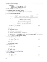
NO TE 1
The figure applies to rim diameter codes 25, 29, 33, 35, 39, 43, 45, 49, 51 and 57. (See Table 7 for specified rim diameters. )
NO TE 2
Flange and bead seat shall be removable on one side.
Figure 1 — Contours of 5 ° full tapered bead seat rims
2
Reprodu ced by I H S u n d er l i cen se wi th BSI - U n con trol l ed Copy
© BSI 04- 1 999
BS AU 50-4-3.1 a:1 998
Table 1 — C ontours of 5 ° full tapered bead seat rims
D imens ions in millimetres
A
G
B
P
± 13
± 2
min.
min.
Rim width code/flange
height code
R
2
tol.
1 1 . 2 5 /2 . 0
2 86
51
32, 5
1 01
32
± 1,5
1 3 . 0 0 /2 . 5
330
63 , 5
45 , 5
1 01
38
± 1,5
330
70
48, 5
1 01
47, 5
± 1,5
1 5 . 0 0/3 . 0 0
3 81
76
55
1 1 7, 5
44, 5
± 1,5
1 5 . 00/3 . 0 –49
3 81
76
55
1 1 7, 5
51
± 2
1 7 . 0 0/2 . 0
43 2
51
32, 5
1 01
32
± 1,5
1 7 . 0 0/3 . 5
43 2
89
58
1 39
51
± 2
1 9 . 5 0/2 . 0
495 , 5
51
32, 5
1 01
32
± 1,5
1 9 . 5 0/2 . 5
495 , 5
63 , 5
45 , 5
1 01
38
± 1,5
1 9 . 5 0/4. 0
495 , 5
1 01 , 5
66
1 39
57
± 2
2 0 . 0 0/2 . 0
508
51
32, 5
1 01
32
± 1,5
2 2 . 0 0/3 . 0
559
76
55
1 39
44, 5
± 1,5
2 2 . 0 0/4. 0
559
1 01 , 5
66
1 39
57
± 2
2 2 . 0 0/4. 5
559
1 1 4, 5
74
1 39
63 , 5
± 2
2 2 . 00/4. 5 –5 1
559
114
74
1 90 , 5
63 , 5
± 2
2 4. 0 0/3 . 0
609 , 5
76
55
1 39
44, 5
± 1,5
2 4. 0 0/5 . 0
609 , 5
127
86, 5
1 90 , 5
70
± 2
2 5 . 0 0/3 . 5
63 5
58
1 39
51
± 2
2 6. 00/5 . 0 –5 1
660 , 5
86, 5
1 90 , 5
70
± 2
2 7 . 0 0/3 . 5
686
58
1 39
51
± 2
2 7 . 0 0/6. 0
686
9 7, 5
1 90 , 5
84
± 2, 5
2 8. 0 0/3 . 5
71 1
58
1 39
51
± 2
2 8. 0 0/4. 0
71 1
1 01 , 5
66
1 39
57
± 2
2 9 . 0 0/6. 0
73 6, 5
1 52, 5
9 7, 5
1 90 , 5
84
± 2, 5
3 1 . 0 0/4. 0
787 , 5
1 01 , 5
66
1 39
57
± 2
3 2 . 0 0/4. 0
81 3
1 01 , 5
66
1 39
57
± 2
3 2 . 0 0/4. 5
81 3
1 1 4, 5
74
1 39
63 , 5
± 2
3 6. 0 0/4. 5
91 4, 5
1 1 4, 5
74
1 39
63 , 5
± 2
1 1 4, 5
74
1 39
63 , 5
± 2
1 3 . 0 0/2 . 7 5
a
40 . 0 0/4. 5
a
1 01 6
89
127
89
1 52, 5
89
For rim diameter code > 49 .
© BS I 0 4- 1 99 9
Reprodu ced by I H S u n d er l i cen se wi th BSI - U n con trol l ed Copy
3
BS AU 5 0-4-3.1 a:1 998
NOTE 1
This figure applies to rim diameter code 25 (see Table 7 for specified rim diameters) .
NOTE 2
Flange and brad seat shall be removable on one side.
Figure 2 — Contours of 5 ° full tapered bead seat rims
Table 2 — C ontours of 5 ° full tapered bead seat rims
Dimensions in millimetres
A
Rim width code/flange
G
height code
tol .
tol.
B
P
min.
min.
R
R
2
± 1,5
8. 50/1 . 3
21 6
± 5
33
± 1,5
25, 5
50
23
8
1 0. 00/1 . 5
254
± 5
38
± 1,5
28
59
25, 5
8
1 2. 00/1 . 3
305
± 6, 5
33
± 1,5
25, 5
47
23
10
1 4. 00/1 . 5
355, 5
± 6, 5
38
± 1,5
28
59
25, 5
10
1 7. 00/1 . 7
432
± 13
43
± 2
25, 5
60
23
4
Reprodu ced by I H S u n d er l i cen se wi th BSI - U n con trol l ed Copy
3
max.
8
© BSI 04- 1 999
BS AU 50-4-3.1 a:1 998
NOTE 1
This figure applies to rim diameter codes 24 and 25 (see Table 7 for specified rim diameters) .
NOTE 2
Flange and bead seat shall be removable on one side
Figure 3 — Contours of semi-drop-centre rims
Table 3 — Contours of semi-drop-centre rims
Dimensions in millimetres
A
Rim width
code/flange height
code
tol.
G
B
P
H
± 1,5
min.
min.
min.
R
2
Rim diameter
code
± 1,5
8. 00 TG SDC
203
± 3, 5
35, 5
1 7, 5
47
1 6, 5
24
1 0. 00 VA SDC
254
± 5
43
25, 5
59
11
23
24
1 2. 00/1 . 3 SDC
305
± 6, 5
33
25, 5
47
7
23
25
1 4. 00/1 . 3 SDC
355, 5
± 6, 5
33
25, 5
47
7
23
25
© BSI 04- 1 999
Reprodu ced by I H S u n d er l i cen se wi th BSI - U n con trol l ed Copy
6, 5
5
BS AU 5 0-4-3.1 a:1 998
NOTE
This figure applies to rim diameter codes 56, 5 and 59, 5 (see Table 7 for specified rim diameters) .
Figure 4 — Contours of 1 5 ° drop-centre rims
Table 4 — Contours of 1 5 ° drop-centre rims
Dimensions in millimetres
A
B
± 10
min.
Rim width code
Ha
La
Q
P
max.
min.
R2
R3
R4
max.
max.
R5a
20. 0
508
57
1 09, 5
1 06
201 , 5
1 20, 5
32
1 9, 5
44, 5
32
22. 0
559
57
1 09, 5
1 57
201 , 5
1 20, 5
32
1 9, 5
44, 5
32
23. 5
597
66, 5
1 31 , 5
111
248
1 52
41
25, 5
48
38, 5
27. 0
686
66, 5
1 31 , 5
200
248
1 52
41
25, 5
48
38, 5
a
These dimensions comprise the minimum well envelope for tyre mounting purposes of dimension
6
Reprodu ced by I H S u n d er l i cen se wi th BSI - U n con trol l ed Copy
Q.
© BSI 04- 1 999
BS AU 50-4-3.1 a:1 998
NOTE
The figure applies to rim diameter codes 24 and 25 (see Table 7 for specified rim diameters) .
Figure 5 — Contours of 5° drop-centre rims
Table 5 — Contours of 5 ° drop-centre rims
Dimensions in millimetres
A
Rim width
G
B
P
H
L
Q
R1
R2
code flange
R3
R4
R5
height code
tol.
tol.
min.
max. min.
min.
min.
max.
0
max.
Rim
diameter
+ 3
code
min.
9. 00/1 . 5
228, 5
± 5, 0
38
± 1,5
25
36
49
48
25, 5
1 02
19
8
14
22
24 max. 24
1 0. 00/1 . 3
254
± 6, 0
33
± 1,5
25
40
49
45
25, 5
1 02
23
10
12
17
1 5 min.
24
1 2. 00/1 . 3
305
± 6, 5
33
± 1,5
25
40
40
45
30
90
23
10
12
17
1 5 min.
25
1 3. 00/1 . 4
330
± 6, 5
36
± 1,5
25
40
40
48
30
1 02
23
10
12
17
1 5 min.
25
1 4. 00/1 . 3
355, 5
± 6, 5
33
± 1,5
25
40
40
45
30
90
23
10
12
17
1 5 min.
25
1 4. 00/1 . 5
355, 5
± 6, 5
38
± 1,5
27
43
40
52
30
90
25, 5 1 0
12
17
1 5 min.
25
© BSI 04- 1 999
Reprodu ced by I H S u n d er l i cen se wi th BSI - U n con trol l ed Copy
7
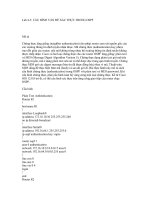
BS AU 5 0-4-3.1 a:1 998
Figure 6 — Transverse knurling details
Table 6 — Knurling widths for rim
D imensions in millimetres
Knurling width
Rim width codes
Fixed flange side
Removable flange side
2 5 min.
51 max.
a) Rim diameter codes 2 5 to 49
1 1 . 2 5 to 1 5. 00
38 min.
1 7. 00 and ab ove
67 max.
67 max.
38 min.
38 min.
67 max.
67 max.
53, 5 min.
53, 5 min.
b ) Rim diameter codes 51 and larger
2 2 . 00 and ab ove
8
Reprodu ced by I H S u n d er l i cen se wi th BSI - U n con trol l ed Copy
© BSI 04- 1 999
BS AU 5 0 -4 -3 . 1 a:1 998
Tab le 7 — E arth-mover sp ecifie d rim
diamete rs
Rim diame te r co de s
S p e cifie d d iame te r,
D
mm
24
61 4, 4
25
63 5 , 0
29
73 6, 6
33
83 8, 2
35
889, 0
39
990, 6
43
1 0 92 , 2
45
1 1 43 , 0
49
1 2 44, 6
51
1 2 95 , 4
57
1 447 , 8
5 6. 5
1 43 5 , 1
5 6. 5
1 51 1 , 3
© BS I 0 4- 1 99 9
Reprodu ced by I H S u n d er l i cen se wi th BSI - U n con trol l ed Copy
9
BS AU 50-4-3.1 a:1 998
Annex A (informative)
Sealing ring grooves and O-rings for
earth-mover rims
10
Reprodu ced by I H S u n d er l i cen se wi th BSI - U n con trol l ed Copy
© BSI 04- 1 999
BS AU 50-4-3.1 a:1 998
Dimensions in millimetres
Rim base
DB
Rim size
;DB
Bead seat ring
R
r
tol.
11-20 SDC
12-20 SDC
13-20 SDC
10.00VA-24 SDC
16.00T-24 SDC
8.00TG-24 SDC
8.50-25/1.3
10.00-25/1.5
11.23-25/1.3
12.00-25/1.3
14.00-25/1.5
17.00-25/1.7
12.00-25/1.3 SDC
14.00-25/1.3 SDC
11.25-25
13.00-25
15.00-25
16.00-25
17.00-25
19.50-25
20.00-25
22.00-25
24.00-25
25.00-25
– 29
– 33
– 35
– 39
– 43
– 45
– 49
– 51
– 57
487,4
T1
DR
; DR
± 0,3
1 531,2
T2
tol.
488,6
L
!
Proposed
O-ring
designation
+2
0
1 535
OR 220
± 1,2
589
1 850,4 ± 1,2
590,2
1 854,2
OR 224
600
609,6
1 885
1,6
601,2
max.
3,2
3,2
1 915,1 ± 2,4
610,8
1 888,8
1,2 5°
5
1 918,9 ± 2,4
OR 225
620,6
1 949,7 ± 1,2
621,8
1 953,4 ± 1,2
600
1 885
602
1 891,2
+ 1,2
– 2,4 4,8
OR 325
+ 1,2
– 2,4 1,6 2°
5,6
7
1,6
1
1
1
1
1
701,6
803,2
854,1
955,7
057,3
108,1
209,7
244,6
397
2 204,1
2 523,3
2 683,2
3 002,4
3 321,6
3 481,2
3 800,4
3 910 ± 2,4
6,4
4 388,8
1
1
1
1
7,2
1
703,6
805,2
856,1
957,7
059,3
110,1
211,7
246,6
399
2 210,4
2 529,6
2 689,5
3 008,7
3 327,9
3 487,5
3 806,7
3 916,3 2,4
4 395,1
OR 329
OR 333
OR 335
OR 339
OR 343
OR 345
OR 349
OR 451
— 15° 9,5
OR 457
NOTE O-ring size, shape and properties should provide a lasting positive seal.
© BSI 04-1999
Reprodu ced by I H S u n d er l i cen se wi th BSI - U n con trol l ed Copy
11
BS AU
5 0-4-3.1 a:1 998
ISO 425 0-3:
BSI — British Standards Institution
1 997
BS I is the indep endent national b ody res p ons ib le for p rep aring
Britis h S tandards . It p res ents the UK view on s tandards in E urop e and at the
international level. It is incorp orated b y Royal C harter.
Revisions
Britis h S tandards are up dated b y amendment or revis ion. Us ers of
Britis h S tandards should make s ure that they p oss es s the latest amendments or
editions .
It is the constant aim of BS I to imp rove the quality of our p roducts and services .
We would b e grateful if anyone finding an inaccuracy or amb iguity while us ing
this Britis h S tandard would inform the S ecretary of the technical committee
res p ons ib le, the identity of which can b e found on the inside front cover.
Tel: 02 0 89 96 90 00. Fax: 02 0 89 96 7 40 0 .
BS I offers memb ers an individual up dating s ervice called PLUS which ens ures
that s ub s crib ers automatically receive the lates t editions of s tandards .
Buying standards
O rders for all BS I, international and foreign s tandards p ub lications s hould b e
addres s ed to C us tomer S ervices. Tel: 0 2 0 899 6 9 00 1 . Fax: 0 2 0 899 6 7001 .
In res p ons e to orders for international standards , it is BS I p olicy to sup p ly the
BS I imp lementation of thos e that have b een p ub lis hed as Britis h S tandards,
unless otherwis e requested.
Information on standards
BS I p rovides a wide range of information on national, E urop ean and
international standards through its Lib rary and its Technical H elp to E xp orters
S ervice. Various BS I electronic information s ervices are also availab le which give
details on all its p roducts and s ervices . C ontact the Information C entre.
Tel: 02 0 89 96 71 1 1 . Fax: 02 0 89 96 7 048.
S ub s crib ing memb ers of BS I are kep t up to date with s tandards develop ments
and receive sub s tantial discounts on the p urchase p rice of s tandards. For details
of thes e and other b enefits contact Memb ership Adminis tration.
Tel: 02 0 89 96 70 02 . Fax: 02 0 89 96 7 00 1 .
Copyright
C op yright s ub s is ts in all BS I p ub lications . BS I als o holds the cop yright, in the
UK, of the p ub lications of the internationalstandardization b odies . E xcep t as
p ermitted under the C op yright, D es igns and Patents Act 1 988 no extract may b e
rep roduced, s tored in a retrieval s ystem or transmitted in any form or b y any
means – electronic, p hotocop ying, recording or otherwis e – without p rior written
p ermis s ion from BS I.
This does not p reclude the free us e, in the cours e of imp lementing the standard,
of necess ary details such as s ymb ols, and size, typ e or grade designations. If thes e
details are to b e used for any other p urp os e than imp lementation then the p rior
written p ermiss ion of BS I must b e ob tained.
If p ermis sion is granted, the terms may include royalty p ayments or a licensing
agreement. D etails and advice can b e ob tained from the C op yright Manager.
BS I
3 89 C his wick H igh Road
London
W4 4AL
Reprodu ced by I H S u n d er l i cen se wi th BSI - U n con trol l ed Copy
Tel: 02 0 89 96 70 7 0.