Bsi bs au 210 2 1994 (1999)
Bạn đang xem bản rút gọn của tài liệu. Xem và tải ngay bản đầy đủ của tài liệu tại đây (812.21 KB, 14 trang )
BRITISH STANDARD
Drawbars for caravans
and light trailers —
Part 2: Specification for the design of
aluminium drawbars and chassis
UDC [629.11-43 + 728.76] :629.11.011.1
BS AU
21 0-2:1 994
BS AU 21 0-2:1 994
Committees responsible for this
British Standard
The preparation of this British Standard was entrusted by the Automobile
Standards Policy Committee (AUE/- ) to Technical Committee AUE/8, upon
which the following bodies were represented:
Association of Trailer Manufacturers
British Compressed Air Society
Caravan Club
Department of Transport
National Caravan Council Limited
Society of Motor Manufacturers and Traders Ltd.
Coopted members
This British Standard, having
been prepared under the
direction of the Automobile
Standards Policy Committee,
was published under the
authority of the Standards
Board and comes
into effect on
1 5 July 1 994
© BSI 1 1 - 1 999
The following BSI references
relate to the work on this
standard:
Committee reference AUE 8
Draft for comment 92 76306 DC
ISBN 0 5 80 223 24 8
Amendments issued since publication
Amd. No.
Date
Comments
BS AU 21 0-2:1 994
Contents
Page
Committees responsib le
Foreword
Inside front cover
ii
1
Scope
1
2
References
1
3
D efinitions
1
4
Symbols
1
5
Resistance calculation for drawbars
4
6
D eflection calculation
4
7
Fatigue
4
8
Mechanical design of chassis
7
9
C hassis strength
7
Joining of b ody to chassis
7
10
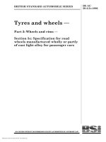
Figure 1 — D rawb ar reference dimensions
2
Figure 2 — Curves relating maximum stress and stress ratio
for 1 0
8
life cycles
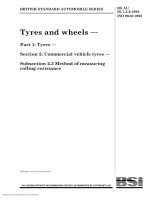
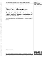
Table 1 — Properties of aluminium alloys
3
Table 2 — Permissible stresses for aluminium alloys
5
List of references
© BSI 1 1 - 1 999
6
Inside back cover
i
BS AU 21 0-2:1 994
Foreword
This Part of BS AU 21 0 was prepared under the direction of the Automobile
Standards Policy Committee. Since the drawbar is only one part of the chassis of
a caravan or light trailer, and as the chassis can be made of materials other than
steel, or even be of composite construction, this Part of BS AU 21 0 aims to set out
requirements for the design of aluminium chassis for caravans and light trailers
A British Standard does not purport to include all the necessary provisions of a
contract. Users of British Standards are responsible for their correct application.
Compliance with a British Standard does not of itself confer immunity
from legal obligations.
Summary of pages
This document comprises a front cover, an inside front cover, pages i and ii,
pages 1 to 8, an inside back cover and a back cover.
This standard has been updated (see copyright date) and may have had
amendments incorporated. This will be indicated in the amendment table on the
inside front cover.
ii
© BSI 1 1 - 1 999
BS AU 21 0-2:1 994
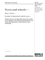
1 Scope
This Part of BS AU 21 0 specifies:
a) a procedure for determining the mechanical
strength of drawbars for caravans and light
trailers where the vertical static force on the
4 Symbols
For the purposes of this Part of BS AU 21 0, the
following symbols are used.
l
is the distance (in mm) from the vertical
axis of the coupling device to the first point
coupling head is not less than 245 N and not
greater than 735 N;
b) requirements for the mechanical design of the
l
on the trailer frame (see Figure 1 ).
x
axis of the coupling device to the drawbar
chassis for caravans and light trailers.
This standard applies to aluminium chassis of
caravans and light trailers provided they are not of
welded construction. It also covers the aluminium
section corresponding to the maximum
strain rate (see Figure 1 ) .
e
is the distance (in mm) from the horizontal
axis of the coupling device to the drawbar
elements of chassis of composite construction, again
neutral axis at the first fixing point on the
provided the aluminium parts have not been
welded.
NOTE
The method for calculation of the mechanical strength of
is the distance (in mm) from the vertical
e
trailer frame (see Figure 1 ).
x
is the distance (in mm) from the horizontal
steel drawbars for caravans and light trailers is covered in
axis of the coupling device to the drawbar
BS AU 21 0- 1 .
neutral axis at the cross section
2 References
(see Figure 1 ).
2.1 Normative references
corresponding to the maximum strain rate
d
is the maximum deflection (in mm) at the
This Part of BS AU 21 0 incorporates, by reference,
coupling device relative to the first fixing
provisions from specific editions of other
point (see Figure 1 ) .
publications. These normative references are cited
at the appropriate points in the text and the
publications are listed on the inside back cover.
Subsequent amendments to, or revisions of, any of
P
D
these publications apply to this Part of BS AU 21 0
This Part of BS AU 21 0 refers to other publications
E
standard are listed on the inside back cover, but
reference should be made to the latest editions.
3 Definitions
(see ISO 3853).
is the modulus of elasticity (in N/mm 2 ); its
value varies according to the alloy
that provide information or guidance. Editions of
these publications current at the time of issue of this
is the value determined by calculation for
the longitudinal force (in N) occurring
between the tractor vehicle and the trailer
only when incorporated in it by updating or revision.
2.2 Informative references
is the manufacturer’s total mass (in kg) of
the caravan or light trailer (see ISO 7237) .
I
g
(see Table 1 ) .
is the moment of inertia (in mm4) ) of the
section.
is the acceleration due to gravity (in m/s 2 )
(see ISO 3853).
For the purposes of this Part of BS AU 21 0, the
definitions given in BS 81 1 8 apply, together with
the following.
3.1
chassis
the element, including the drawbar, between the
axle assembly and the body of the caravan or light
trailer
3.2
drawbar
that part of the chassis which enables the
connection of the caravan or light trailer to the
towing vehicle
© BSI 1 1 - 1 999
1
BS AU 21 0-2:1 994
Figure 1 — Drawbar reference dimensions
2
© BSI 1 1 - 1 999
© BSI 11-1999
TF
H3
H2
TB
TF
O
TF
TE
TF
TB
M
TF
drawn tube
extrusions
sheet
extrusions
sheet and plate
extrusions
extrusions
extrusions
extrusions
extrusions
clad sheet
clad plate
sheet
sheet
extrusions
sheet and plate
extrusions
sheet and plate
sheet and plate
extrusions
Form
20
150d
3.0
25
6.0
10
150d
25
150d
25
150d
25
150d
20
20
12.5
25
6.0
6.0
25
25
25
25
mm
mm
—
20
0.2
3.0
—
6.0
—
3.0
—
0.2
—
—
—
—
—
3.0
12.5
0.2
0.2
—
0.2
—
0.2
Max.
Min.
Thickness
255
270
255
240
255
240
130
—
125
160
110
240
230
370
365
380
130
165
190
170
280
270
295
310
295
295
310
310
280
—
275
185
150
280
370
435
425
440
200
245
300
280
340
320
10
8
8
—
—
7
—
12
—
14
14
8
8
8
11
7
—
6
—
—
12
8
7
—
8
8
7
9
11
—
13
12-16
7
7
7
10
6
8
—
4-8
5-8
10
same as
tensile
115
150
same as
tensile
same as
tensile
tensile
206
118
same as
tensile
same as
tensile
556
525
556
386
324
556
664
772
726
463
494
600
560
660
630
618
587
618
71 700
68 900
68 900
65 500
68 900
72 400
68 900
68 900
2 800 B
2 710 B
2 710 B
C
2 800
Ae
2 690 A
2 670
2 660 A
2 710 B
Elongation
0.2 %
0.2 %
Bearing Modulus
tensile Tensile
of
Density Durability
proof strength 5.65 Ỉ S0 50 mm compressive
strength
proof stress
elasticityb
stress
ratingc
%
%
N/mm2
N/mm2
N/mm2
kg/m3
N/mm2 N/mm2
a See BS 1470.
b For modulus of rigidity multiply by 0.38.
c See BS 8118-1:1991 clause 2.4 .
d For round tube and hollow sections these properties do not apply above 75 mm.
e C for immersion in fresh or sea water.
7020
5251
5154A
2014A
6063
6061
5083
6082
Alloy BS or
international
Condition
no. a
Table 1 — Properties of aluminium alloys
BS AU 210-2:1994
3
BS AU 21 0-2:1 994
5 Resistance calculation for drawbars
6 Deflection calculation
5 .1 The calculation for resistance for drawbars shall
6.1 The deflections
be carried out over the whole length
at the same time as the resistance calculation in
l of the
drawbar, taking into account distances l and e
x
x
in
order to determine the maximum strain rate. The
strain rate shall be checked at the position where
the maximum bending moment occurs when
and
e=e.
x
d
fR
shall be calculated,
x
f
x
x
— For braked trailers:
f
and
— For braked trailers:
d
Only flexure is taken into account for the calculation.
M = 0. 36 Pgl
fD
clause 5 , as follows.
be calculated as follows.
NOTE
f
M (in N·mm)
e/l < 0. 1 5 and e /l < 0. 1 5 shall
5 .2 The maximum bending moment
for the drawbar with
l=l
d,d
fR
d +d
= 0. 75 (
f
fD )
— For unbraked trailers:
x
— For unbraked trailers:
M = 0. 24 Pgl
f
x
5 .3 The maximum bending moment (in N·mm) for
the drawbar with
e/l > 0. 1 5 and e /l
x
x
> 0. 1 5 shall be
d
calculated as follows.
NOTE
Only flexure is taken into account for the calculation.
Three bending moments
M, M
f
fD
and
M
fR
shall be
calculated and the largest value of the three shall be
fR
d +d
= 0. 75 (
f
fD )
The value shall not exceed that defined in 6.2
NOTE
Because of the increased flexibility of aluminium
compared to steel, it should not be taken for granted that the
used for the calculation of the maximum admissible
drawbar design is sufficiently stiff without performing a
stress
deflection calculation.
M
fmax .
6.2 The permissible deflection
— For braked trailers:
M = 0. 36 Pgl
M = 0. 8 De
M = 0. 75 (M + M
f
device shall not exceed:
x
fD
d
x
fR
f
M = 0. 24 Pgl
M = 1 . 0 De
M = 0. 75 (M + M
Because of the constraints on manufacture, all
drawbars shall be considered to have type 1
x
fR
f
classification as defined in BS 81 1 8- 1 : 1 991 .
fD )
5 .4 The permissible stress rates
B, calculated for the
whole length of the drawbar, shall not exceed the
allowed stress
B
bc
to a maximum of 25 mm.
7 Fatigue
x
fD
l
70
fD )
— For unbraked trailers:
f
=
d at the coupling
(see Table 2).
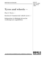
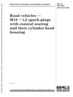
Using the curves in Figure 2, the fatigue life shall be
predicted.
NOTE
Bmin
is the minimum stress, which is the lower numerical
value of the stress in a stress cycle.
Bmax
I/V
3
is the section modulus (in mm ), of the
drawbar cross section corresponding to the
maximum bending moment.
NOTE
is the maximum stress, which is the higher numerical
value of the stress in a stress cycle.
where
It is assumed in this standard that aluminium sheet,
plate or strip conforming to BS 1 470 or bars, extruded round tube
Ömin
Ömax
is the stress ratio, which is the ratio of the minimum
to maximum stress in a stress cycle, tensile stress
being considered positive and compressive stress
negative.
When these points are plotted on Figure 2a) and Figure 2b) ,
they always occur on the curve or in the area defined as
“acceptable”.
or sections conforming to BS 1 474 are used. This does not prevent
other, suitable and fit for purpose, aluminium alloys being used.
The properties of some aluminium alloys are shown in Table 1
and Table 2.
4
© BSI 1 1 - 1 999
BS AU 21 0-2:1 994
Table 2 — Permissible stresses for aluminium alloys
Thickness
Alloy BS or
international
no.
C ondition
Form
Min.
Max.
mm
mm
a
Axial
B
Bending
B
t
N/mm
b
B
c
2
N/mm
2
B
bt
N/mm
2
Shear
B
bc
N/mm
N/mm
TF
1 39
1 39
1 54
1 54
83
20
1 50
1 47
1 47
1 62
1 62
88
1 39
1 39
1 54
1 54
83
1 32
1 32
1 47
1 47
79
1 40
1 40
1 56
1 56
84
1 34
1 34
1 49
1 49
80
82
82
96
96
49
2 01
80
77
94
90
48
2 01
80
77
94
90
48
2 01
87
87
96
96
52
1 39
62
62
69
69
37
117
1 31
1 31
1 45
1 45
78
2 01
0. 2
plate
3. 0
3. 0
21 2
—
25
6. 0
222
6. 0
sheet and
2
222
drawn tube
M
c
b
N/mm
20
sheet and
extrusions
2
—
extrusions
6082
B
q
2
Bearing
—
3. 0
10
1 50
d
25
plate
5083
extrusions
O
sheet and
—
0. 2
1 50
d
25
plate
TF
extrusions
—
1 50
TE
extrusions
—
25
d
6063
6061
d
TF
extrusions
—
1 50
TB
extrusions
—
20
1 35
124
1 53
1 42
81
2 39
extrusions
—
20
1 54
2 02
1 54
224
1 08
2 78
1 2. 5
1 47
1 99
1 47
220
1 00
2 61
25
1 47
2 07
1 47
229
2 01 4A
TF
clad sheet
3. 0
clad plate
1 2. 5
52 51
H3
sheet
0. 2
6. 0
75
69
85
79
45
1 67
51 54A
H2
sheet
0. 2
6. 0
95
88
1 07
1 00
57
1 78
25
111
111
126
1 26
67
216
25
1 00
1 00
114
114
60
2 02
25
1 54
1 54
1 71
1 71
92
2 38
25
1 48
1 48
1 64
1 64
89
227
extrusions
TB
sheet and
—
0. 2
plate
702 0
extrusions
TF
sheet and
—
0. 2
plate
a
b
c
d
See BS 1 470.
Applies only when buckling is not the criterion; see BS 81 1 8- 1 .
Joints in single shear.
For round tub e and hollow sections the permissible stresses do not apply ab ove 75 mm.
© BSI 1 1 - 1 999
5
Figure 2 — C urves relating maximum stress and stress ratio and 1 0
8
life cycles
BS AU 21 0-2:1 994
6
© BSI 1 1 - 1 999
BS AU 21 0-2:1 994
8 Mechanical design of chassis
8.1 Bolted j oints
Minimum spacing between bolt holes
The spacing between the centres of the bolts shall
not be less than 2.5 times the bolt diameter.
8.1 .2 Edge distance
With extruded, rolled or machined edges, the
distance to the edge, measured from the centre of
the bolt hole shall not be less than 1.5 times the bolt
diameter. If, on the beating side, it is less than 2
times the bolt diameter, the permissible beating
strength shall be reduced as follows:
8.1 .1
where
is the modified bearing strength;
is the bearing strength given in Table 2;
is the actual ratio of edge distance to bolt
diameter;
r
is the ratio of edge distance to bolt
diameter.
8.1 .3 Web stiffness
The web stiffness shall be demonstrated by
calculation as detailed in BS 8118-1:1991, by test or
both.
8.1 .4 Bolt material
Steel bolts conforming to BS EN 24014:1992 and
nuts to BS EN 24032:1992 shall be used. Both the
bolts and nuts used shall be rendered corrosion
resistant by zinc plating to BS 3382-2:1961.
Washers shall be provided under all bolt heads and
nuts and these washers shall be zinc plated to
BS 1706:1990 Fe/Zn 8 and passivated. The length of
the unthreaded part of the bolt shall be such that as
far as possible no part of the thread is within the
thickness of the member The thread shall project
beyond the nut by a minimum of two turns. A form
of locking device shall be used.
PBM
PB
ra
c) painted with priming coat with an inhibiting
pigment containing not less than 20 % by weight
of zinc chromate or other approved chromate in a
suitable water resisting vehicle. The priming coat
shall not contain any copper or mercury
compounds, graphite or carbonaceous materials,
or lead; or
d) separated by the use of a continuous
membrane of non-reactive material e.g. plastic.
NOTE A joint made by any other means not detailed in this
standard may be used provided that its load carrying capacity
and life expectancy can be shown to be satisfactory.
8.3 Contact with timber
Aluminium surfaces in contact with timber, unless
the timber is fully seasoned and the environment
dry and unpolluted, shall be painted. Timber in
contact with aluminium shall not be treated with
preservatives containing copper sulfate, zinc
chloride or mercuric salts.
NOTE 1 Other preservatives may be used provided that it can
be shown that the timber so treated is not harmful to the
aluminium.
NOTE 2 Oak, chestnut and western red cedar are likely to be
harmful to aluminium particularly where there are through
fastenings, unless the timber is well seasoned.
9 Chassis strength
The chassis manufacturer shall demonstrate, either
by test or by calculation, or both, that all elements
of the chassis are fit for their declared purpose with
reference to BS 8118:1991.
1 0 Joining of body to chassis
The chassis manufacturer shall provide, in writing,
instructions in respect of strength and fixing
arrangements for the attachment of the caravan or
light trailer body to the chassis. There shall be no
fixing directly or indirectly through the top or
bottom flanges of the drawbar at the foremost body
fixing position.
NOTE Other suitable anti-corrosion coatings may be used that
adequately protect the jointed parts against electrolytic
corrosion.
(see also 8.3 )
For such composite joints, the steel or cast iron
elements shall be either:
a) zinc plated to BS 1706:1990 Fe/Zn 8; or
b) hot dip galvanized to BS 729:1971; or
8.2 Joints with steel or cast iron
© BSI 11-1999
7
8
blank
BS AU 21 0-2:1 994
List of references
(see clause 2 )
Normative references
BSI publications
BRITISH STANDARDS INSTITUTION, London
BS 729:1971,
BS 1706:1990,
BS 3382,
BS 3382-1 & BS 3382-2:1961,
BS 8118,
BS 8118-1:1991,
BS 8118-2:1991,
BS EN 24014:1992,
BS EN 24032:1992,
Sp ecification fo r ho t dip galv anized coatings o n iron and steel articles .
Method for sp ecifying electrop lated coatings of zinc and cadm ium ,
on iron and steel.
Sp ecificatio n fo r electrop lated coatings on threaded com p onents .
Cadm ium o n s teel com p onents.
Zinc on steel com p o nents.
Structural us e of alum inium .
Code of p ractice fo r design.
Sp ecification fo r m aterials,
w o rkm anship and p rotectio n.
Hexago n head b olts — Product grades A and B.
Hexagon nuts,
style 1
— Product grades A and B.
Informative references
BSI publications
BRITISH STANDARDS INSTITUTION, London
BS AU 210,
BS AU 210-1:1987,
BS 1470:1987,
Draw b ars fo r carav ans and light trailers.
Method o f calculation for the m echanical s trength of steel draw b ars .
Sp ecification fo r w rought alum inium and alum inium alloys for general engineering
p urp oses: p late,
BS 1474:1987,
p urp o ses: b ars,
Sp ecificatio n fo r w rought alum inium and alum inium ,
ISO 7237:1981,
ISO 3853:1977,
Strength test.
© BSI 11-1999
sheet and strip .
alloys fo r general engineering
extruded ro und tub es and sections.
Road v ehicles — Mass es and dim ensions o f carav ans — Term s and definitio ns.
Road vehicles — Carav ans and light trailers — Tow ing b rackets and co up ling b alls —
BS AU
21 0-2:1 994
BSI — British Standards Institution
BS I is the indep endent national b ody res p ons ib le for p rep aring
Britis h S tandards . It p res ents the UK view on s tandards in E urop e and at the
international level. It is incorp orated b y Royal C harter.
Revisions
Britis h S tandards are up dated b y amendment or revis ion. Us ers of
Britis h S tandards should make s ure that they p oss es s the latest amendments or
editions .
It is the constant aim of BS I to imp rove the quality of our p roducts and services .
We would b e grateful if anyone finding an inaccuracy or amb iguity while us ing
this Britis h S tandard would inform the S ecretary of the technical committee
res p ons ib le, the identity of which can b e found on the inside front cover.
Tel: 02 0 89 96 90 00. Fax: 02 0 89 96 7 40 0 .
BS I offers memb ers an individual up dating s ervice called PLUS which ens ures
that s ub s crib ers automatically receive the lates t editions of s tandards .
Buying standards
O rders for all BS I, international and foreign s tandards p ub lications s hould b e
addres s ed to C us tomer S ervices. Tel: 0 2 0 899 6 9 00 1 . Fax: 0 2 0 899 6 7001 .
In res p ons e to orders for international standards , it is BS I p olicy to sup p ly the
BS I imp lementation of thos e that have b een p ub lis hed as Britis h S tandards,
unless otherwis e requested.
Information on standards
BS I p rovides a wide range of information on national, E urop ean and
international standards through its Lib rary and its Technical H elp to E xp orters
S ervice. Various BS I electronic information s ervices are also availab le which give
details on all its p roducts and s ervices . C ontact the Information C entre.
Tel: 02 0 89 96 71 1 1 . Fax: 02 0 89 96 7 048.
S ub s crib ing memb ers of BS I are kep t up to date with s tandards develop ments
and receive sub s tantial discounts on the p urchase p rice of s tandards. For details
of thes e and other b enefits contact Memb ership Adminis tration.
Tel: 02 0 89 96 70 02 . Fax: 02 0 89 96 7 00 1 .
Copyright
C op yright s ub s is ts in all BS I p ub lications . BS I als o holds the cop yright, in the
UK, of the p ub lications of the international s tandardization b odies . E xcep t as
p ermitted under the C op yright, D es igns and Patents Act 1 988 no extract may b e
rep roduced, s tored in a retrieval s ystem or transmitted in any form or b y any
means – electronic, p hotocop ying, recording or otherwis e – without p rior written
p ermis s ion from BS I.
This does not p reclude the free us e, in the cours e of imp lementing the standard,
of necess ary details such as s ymb ols, and size, typ e or grade designations. If thes e
details are to b e used for any other p urp os e than imp lementation then the p rior
written p ermiss ion of BS I must b e ob tained.
If p ermis sion is granted, the terms may include royalty p ayments or a licensing
agreement. D etails and advice can b e ob tained from the C op yright Manager.
BS I
3 89 C his wick H igh Road
London
W4 4AL
Tel: 02 0 89 96 70 7 0.