Bsi bs au 050 2 5c 1996 (1999)
Bạn đang xem bản rút gọn của tài liệu. Xem và tải ngay bản đầy đủ của tài liệu tại đây (724.92 KB, 20 trang )
BRITISH STANDARD AUTOMOBILE SERIES
Tyres and wheels —
Part 2: Wheels and rims —
Section 5c: Specification for road
wheels manufactured wholly or partly
of cast light alloy for passenger cars
Reprodu ced by I H S u n d er l i cen se wi th BSI - U n con trol l ed Copy
BS AU
50-2.5 c:1 996
BS AU 5 0-2.5c:1 996
Committees responsible for this
British Standard
The preparation of this British Standard was entrusted to Technical
Committee AUE/4, Tyres and wheels for road vehicles, upon which the
following bodies were represented:
Agricultural Engineers’ Association
Automobile Association
British Industrial Truck Association
British Pressure Gauge Manufacturers’ Association
British Rubber Manufacturers’ Association
Confederation of Passenger Transport UK
Department of Transport
Freight Transport Association
Institute of Road Transport Engineers (Inc)
Motor Cycle Industry’s Association of Great Britain Ltd.
Motor Industry Research Association
National Tyre Distributors’ Association
Retread Manufacturers’ Association
Road Haulage Association Ltd.
Society of Motor Manufacturers and Traders Ltd.
This British Standard, having
been prepared under the
direction of the Engineering
Sector Board, was published
under the authority of the
Standards Board and comes
into effect on
1 5 April 1 996
© BSI 07- 1 999
Amendments issued since publication
First published July 1 976
Amd. No.
Second edition April 1 996
The following BSI references
relate to the work on this
standard:
Committee reference AUE/4
Draft for comment 94/71 3765 DC
ISBN 0 5 80 25 366 X
Reprodu ced by I H S u n d er l i cen se wi th BSI - U n con trol l ed Copy
Date
Comments
BS AU 5 0-2.5 c:1 996
Contents
Page
Committees responsible
Inside front cover
Foreword
ii
5. 1
Scope
1
5. 2
References
1
5. 3
Definitions
1
5. 4
Materials
1
5. 5
Protection of magnesium alloy castings and finished wheels
2
5. 6
Tests on completed wheels
2
5. 7
Documentation
2
5. 8
Marking
2
5. 9
Valve holes
3
Annex A (normative) Quality control/test schedule
6
Annex B (normative) Validation procedure
6
Annex C (normative) Conformity of production
7
Annex D (normative) Tyre fitting test. Procedure for the
introduction of new or modified rim profiles
7
Annex E (normative) Dynamic cornering fatigue test
7
Annex F (normative) Dynamic radial fatigue test
8
Annex G (normative) Impact test
8
Annex H (normative) Testing of finishing systems
9
Annex J (informative) Guidance on certain aspects of
wheel attachment systems
11
Figure 1 — Typical wheels
3
Figure 2 — Wheel nomenclature
4
Figure 3 — Valve holes
10
Figure G. 2 — Machine calibration method
11
List of references
© BSI 07- 1 999
Reprodu ced by I H S u n d er l i cen se wi th BSI - U n con trol l ed Copy
5
Figure G. 1 — Wheel impact machine
Inside back cover
i
BS AU 5 0-2.5c:1 996
Foreword
This S ection of BS AU 5 0 has b een p rep ared b y Technical C ommittee AUE /4. It
sup ersedes BS AU 5 0- 2 . 5 : 1 976, which is withdrawn.
The increas ed p erformance of p ass enger cars led in the 1 97 0s to the us e for the
road wheels of light alloys , generally of aluminium or magnes ium, which offer a
favourab le strength to weight ratio. The firs t edition of BS AU 5 0 - 2 . 5 was
p ub lis hed in 1 97 6 to ensure that the quality of des ign and p roduction was
adequately controlled.
This new edition incorp orates Amendment 1 and Amendment 2 to
BS AU 5 0- 2 . 5 : 1 97 6, and introduces technical changes as follows:
— in
E .1
a maximum length of moment arm is s p ecified;
— in
E .3
the value for
— in
G.3
an additional op tion for the tyre has b een allowed for original
È
and the exp res sion for
R
have b een changed;
equip ment wheels .
References to other s tandards have also b een reviewed and, where p oss ib le, are
now undated. This new edition does not, however, cons titute a full revis ion of the
standard.
Tyre, wheel, rim and valve requirements are given in the following Parts and
S ections of BS AU 5 0 :
—
Part 1: Tyres;
—
Section 0: General;
—
Section 1: Car tyres;
—
Section 2: Commercial vehicle tyres;
—
Section 3: Off-the-road tyres;
—
Section 4: Agricultural tractor and machine tyres;
—
Section 5: Industrial vehicle tyres;
—
Section 6: Motorcycle tyres;
—
Section 7: Moped tyres;
—
Section 8: Code of practice for the storage of tyres, inner tubes and flaps;
—
Part 2: Wheels and rims;
Section 0: General (including terms and definitions, and construction and
workmanship);
—
—
Section 1: (Withdrawn);
Section 2: Specification for dimensions of wheel naves and hub centres for
commercial vehicles;
—
— Section 3: Specification for road-wheel nuts, studs and bolts for commercial
vehicles;
Section 5: Specification for road wheels manufactured wholly or partly of
cast light alloy for passenger cars;
—
Section 6: Specification for road wheels manufactured wholly or partly of
light alloy for mopeds and motor cycles;
—
— Section 7: Code of practice for the selection and care of tyres and wheels for
commercial vehicles;
Section 8: Code of practice for the selection and care of wheels for passenger
cars (including caravans and light trailers);
—
ii
Reprodu ced by I H S u n d er l i cen se wi th BSI - U n con trol l ed Copy
—
Part 3: Valves;
—
Section 1: Specification for valve dimensions;
—
Section 2: Tyre valve threads 5V1, 5V2, 6V1 and 8V1 ;
—
Section 3: Tyre valve threads 9V1, 10V2, 12V1 and 1 3V1;
© BS I 0 7 - 1 9 9 9
BS AU 5 0-2.5 c:1 996
— Section 4: Tyre valve threads 8V2, 1 0V1, 11 V1, 13V2, 1 5V1, 16V1, 17V1 ,
17V2, 17V3, 19V1 and 20V1;
—
Section 5: Dimensions for ISO core chamber No. 1 for tyre inflation valves;
—
Section 6: Dimensions for ISO core chamber No. 2 for tyre inflation valves;
Section 7: Code of practice for the selection and care of tyre inflation valves
for passenger cars (including caravans and light trailers);
—
— Section 8: Code of practice for the selection and care of tyre inflation valves
for commercial vehicles;
—
Part 4: Rim profiles and dimensions;
—
Section 1 : Car rims;
—
Section 2: Commercial vehicle rims;
—
Section 3: Off-the-road rims;
—
Section 4: Agricultural tractor and machine rims;
—
Section 5: Industrial vehicle rims;
—
Section 6: Motorcycle rims;
—
Section 7: Moped rims.
A British Standard does not purport to include all the necessary provisions of a
contract. Users of British Standards are responsible for their correct application.
Compliance with a British Standard does not of itself confer immunity
from legal obligations.
Summary of pages
This document comprises a front cover, an inside front cover, pages i to iv,
pages 1 to 1 2, an inside back cover and a back cover.
This standard has been updated (see copyright date) and may have had
amendments incorporated. This will be indicated in the amendment table on
the inside front cover.
© BSI 07- 1 999
Reprodu ced by I H S u n d er l i cen se wi th BSI - U n con trol l ed Copy
iii
iv
Reprodu ced by I H S u n d er l i cen se wi th BSI - U n con trol l ed Copy
blank
BS AU 50-2.5c:1 996
5.1 Scope
This Section of BS AU 50- 2 specifies performance
5.3.4
wheel loading
requirements and methods of test for wheels with
the mass supported by a wheel
any structural element of light alloy for use on all
5.3.5
passenger cars and three- wheeled motorcycles
specific application wheel
having an unladen weight greater than 255 kg.
NOTE
Requirements for light alloy wheels for use on
three- wheeled motor cycles having an unladen weight less
than 255 kg are given in BS AU 50- 2. 6.
5.2 References
a wheel designed to meet the specification
determined by the vehicle manufacturer
5.3.6
general application wheel
a wheel designed so that one basic casting may be
5.2.1 Normative references
used for wheels to be utilized for a variety of vehicles
This Section of BS AU 50 incorporates, by dated or
5.3.7
undated reference, provisions from other
radiological standard
publications. These normative references are made
at the appropriate places in the text and the cited
publications are listed on the inside back cover. For
dated references, only the edition cited applies; any
subsequent amendments to or revisions of the cited
publication apply to this Section of BS AU 50 only
when incorporated in the reference by amendment
permanent radiographic record of the basic design of
wheel showing the minimum acceptance standard
as agreed between the founder and the wheel
manufacturer
5.4 Materials
or revision. For undated references, the latest
The materials used to manufacture cast light alloy
edition of the cited publication applies, together
road wheels shall be such that the performance
with any amendments.
requirements of this standard are met, see Annex A.
5.2.2 Informative references
This Section of BS AU 50 refers to other
NOTE
The materials used should preferably conform to either
BS 1 490 or BS 2970, however in order to permit the development
and application of alloys not included in the above standards,
publications that provide information or guidance.
other light alloys may be used.
Editions of these publications current at the time of
Cast light alloys, whether or not included in
issue of this standard are listed on the inside back
BS 1 490 or BS 2970, shall have suitably specified
cover, but reference should be made to the latest
chemical compositions, mechanical properties and
editions.
5.3 Definitions
For the purposes of this Section of BS AU 50 the
definitions given in BS AU 50- 1 . 0 and BS AU 50- 2. 0
other physical requirements which shall be defined
and agreed between the founder and the wheel
manufacturer with particular attention being given
to the influence of age hardening and stress
corrosion.
apply, together with the following.
Whatever the light alloys used in the manufacture
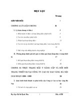
See also Figure 2.
of road wheels conforming to this Section of
5.3.1
centre member (disc, spider or spoked)
the connection between the vehicle hub and the
wheel rim
BS AU 50, the inspection and quality control for cast
aluminium and cast magnesium alloys shall
conform to BS 1 490 or BS 2970 respectively,
including the additional inspection and test
procedures for analysis, together with optional
5.3.2
procedures as agreed between the founder and the
nave
wheel manufacturer.
central portion of centre member, where the wheel
mounting face and fixing features are usually
located
NOTE
In the case of BS 2970: 1 989 this corresponds to the
classification QC/TS (quality controlled to a test schedule) . In the
case of BS 1 490: 1 988 this corresponds to supplementary test
code A, with other test codes as agreed in the test schedule.
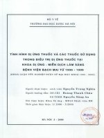
5.3.3
Materials other than cast light alloys used to make
offset
parts of a composite wheel shall conform to the
the distance between the mounting face of the nave
and the centre- line of the rim (see Figure 1 ). The
distance is termed positive (inset) when the
appropriate British Standards (see A.3 ). In making
use of such materials, cognizance shall be taken of
the compatibility of dissimilar materials.
mounting face is outboard of the rim centre- line and
negative (outset) when inboard of the rim
centre- line
© BSI 07- 1 999
Reprodu ced by I H S u n d er l i cen se wi th BSI - U n con trol l ed Copy
1
BS AU 5 0-2.5c:1 996
If suitable British Standard specifications are not
available, the requirements for the materials shall
be specified and agreed between the founder and the
wheel manufacturer.
5 .5 Protection of magnesium alloy
castings and finished wheels
The protective treatment against corrosion shall be
applied by the founder and/or the wheel
manufacturer. All surfaces on magnesium wheels
shall be fully protected.
Tyre fitting test
5.6.4.2
Wheel rim profiles not conforming to the
requirements of BS AU 50- 4. 1 shall conform to the
criteria for acceptance specified in Annex D.
5.6.4.3 Dynamic cornering fatigue test
(separate wheel)
Wheels shall be subj ected to the dynamic cornering
fatigue test described in Annex E, and shall conform
to the criteria for acceptance specified in E.4
and E.5 .
5.6.4.4
Dynamic radial fatigue test (separate
5 .6 Tests on completed wheels
wheel)
5.6.1 Design approval
Wheels shall be subj ected to the dynamic radial
To conform to the requirements of this Section of
this standard, wheels shall first have the design
validated by test samples, which shall demonstrate
conformity to 5.6.4 . Any change in detail design or
fatigue test described in Annex F, and shall conform
to the criteria for acceptance specified in F.4
and F.5 .
5.6.4.5
Impact test (separate wheel)
alloy specification shall be followed by revalidation.
Wheels shall be subj ected to the impact test
Revalidation shall also follow any change in the
described in Annex G, and shall conform to the
finishing system which results in changes in the
criteria for acceptance specified in G.7 and G.8 .
residual surface stress condition.
5.6.4.6
NOTE
In the case of wheels for general application, test
specimens may be selected, using the procedure described in
Annex B.
5.6.2 C onformity of production
Finishing systems
Inboard parts of all wheels, the rim area covered by
the tyre, whether polished or not, and any other
unpolished areas, shall be protected to conform to
the requirements of Annex H. A finished wheel (not
For sampling rates, see Annex C. The minimum
test panels) shall be used for the salt spray test
rate of testing should be in accordance with the
specified in H.2.1 .
recommendations given in C.1 .
It shall be the responsibility of the wheel
The results of the tests shall be interpreted, and
manufacturer and the retailer to include with the
re- examined or retesting carried out, in accordance
sale of polished wheels a warning of the effects of
with the criteria specified in C.2 .
corrosion on the polished areas, and to make
5 .6.3 Preparation of test wheels
recommendations regarding protection.
Tests shall be carried out on fully- finished wheels
NOTE
representative of normal production except in those
cases where permanent coatings have been applied
which cannot be removed by simple chemical
processes without damage to the wheels, this
Guidance on some aspects of the design of wheel
attachment systems is given in Annex J.
5.7 Documentation
Chemical analysis certificates and/or hot metal
coating removal being necessary to permit
suppliers’ analysis certificates, chemical analysis
penetrant- dye crack detection to be carried out. In
records, mechanical test records, heat treatment
these exceptional cases it shall be permissible to test
furnace charts, dimensional records and records of
uncoated wheels, provided that the wheels have
conformity to the performance tests specified
undergone the complete heat- stoving cycle
in 5 .6.4 appertaining to all wheels shall be retained
applicable to the coating process.
for a minimum period of 6 years.
5 .6.4 Performance requirements
5 .6.4.1
General
All wheels manufactured to this standard shall
conform to the following performance requirements.
5.8 Marking
Wheels shall be marked with the following
information:
a) the number of this British Standard,
i. e. BS AU 50- 2. 5c: 1 996
1)
1)
;
Marking BS AU 50- 2. 5c: 1 996 on or in relation to a product represents a manufacturer’s declaration of conformity, i. e. a claim
by or on behalf of the manufacturer that the product meets the requirements of the standard. The accuracy of the claim is solely
the claimant’s responsibility. Such a declaration is not to be confused with third party certification of conformity, which may also
be desirable.
2
Reprodu ced by I H S u n d er l i cen se wi th BSI - U n con trol l ed Copy
© BSI 07- 1 999
BS AU 5 0-2.5 c:1 996
b) the country of origin;
The above markings shall be permanent and visible
c) the trademark or other means of identification
when the wheel is fitted with a tyre.
of the manufacturer;
d) the size of the wheel (including offset). In the
case of specific application wheels, including
5 .9 Valve holes
The hole provided in the wheel rim to accommodate
those supplied as original equipment, these shall
the tyre valve shall conform to the dimensions given
be marked with the vehicle manufacturer’s part
in Figure 3 for clamp- in, snap- in or tube valves.
number for the model for which the wheel has
Particular attention shall be paid to the control of
been approved;
depth on counterbores and due note taken that, in
e) the maximum wheel loading as determined by
many standard rim profiles, the counterbore on the
the vehicle or wheel manufacturer;
outer face may come very close to “breaking
f) an indication of the date of production of the
wheel.
through”. In this event, consideration should be
given to increasing the well depth of the rim profile.
Figure 1 — Typical wheels
© BSI 07- 1 999
Reprodu ced by I H S u n d er l i cen se wi th BSI - U n con trol l ed Copy
3
BS AU 5 0-2.5c:1 996
Figure 2 — Wheel nomenclature
4
Reprodu ced by I H S u n d er l i cen se wi th BSI - U n con trol l ed Copy
© BSI 07- 1 999
BS AU 5 0-2.5 c:1 996
NO TE 1
S ufficient s p ace s hould b e availab le for acces s ib ility to the valve mouth b y hand and b y tyre p res s ure gauge. Additionally,
any s p ecific requirements to p ermit fitment of the intended valve typ e s hould b e agreed b etween the s p ecifier and. the wheel
manufacturer.
NO TE 2
No s harp edges or b urrs are p ermitted at the rim hole.
NO TE 3
All faces to b e p arallel.
NO TE 4
Break all s harp edges .
NO TE 5
Where wheel p rofiles exceed the minimum dimens ions quoted, no counterb oring is neces s ary.
Figure 3 — Valve holes
© BS I 0 7- 1 99 9
Reprodu ced by I H S u n d er l i cen se wi th BSI - U n con trol l ed Copy
5
BS AU 50-2.5c:1 996
Annex A (normative)
Quality control/test schedule
A.1 Cast material
Light alloys, whether or not included in BS 1 490 or
BS 2970, shall have suitable specified chemical
compositions, mechanical properties and other
physical requirements, which are defined and
A.2.3.2
Tensile test bars taken from wheels
The position of the test bars machined from the
wheels shall be clearly defined on the drawing and
the frequency with which they are to be taken shall
be specified.
A.2.3.3
Micro- structure
Where this is required to be checked, the
agreed between the founder and the wheel
micro- structure and type of etchant shall be agreed
manufacturer with particular attention to age
and the areas and frequency of examination shall be
hardening and stress corrosion.
specified.
A.2 Tests
A.3 Metals other than cast light alloy
A.2.1 General
A.3.1 The metal preferably should conform to an
The following tests are in addition to those specified
appropriate British Standard.
in BS 1 490 and BS 2970; they shall be carried out at
A.3.2 Whether or not a suitable British Standard
a frequency and to a minimum standard of
exists, a detailed specification shall be drawn up to
acceptance agreed between the founder and the
include all relevant data and processing
wheel manufacturer.
instructions which shall be submitted to the wheel
A.2.2 Non-destructive tests
A.2.2.1
Production inspection
Each casting shall be subj ected to either a penetrant
dye inspection for freedom from linear defects or
X- ray examination to ensure conformity to the
radiological standard. Whichever method is used,
there should be cross- checking by the other method
at such frequency as to ensure that the level of
acceptance is maintained.
For composite wheels, appropriate inspection
procedures shall be employed for components and
manufacturer for agreement.
A.3.3 Tests should be as specified by an appropriate
British Standard. If no suitable British Standard
exists, a detailed schedule shall be drawn up. This
schedule shall include not only tests relating to
materials, but also to features of assembly
(e. g. rivets, bolts and nuts, welding).
Annex B (normative)
Validation procedure
B.1 Application groups
their attachments manufactured from materials
Light alloy wheels for passenger cars generally fall
other than light alloys (see also A.3 ).
into two distinct groups, termed “specific
A.2.2.2
Penetrant dye
The type of penetrant dye used and the inspection
procedures shall be specified.
For frequency of testing see A.2.2.1 .
A.2.2.3
Radiological inspection
A radiological standard of acceptance shall be
application” and “general application”. Wheels
supplied as original equipment (OE) are included in
specific application.
B.2 Design validation procedure
B.2.1 Wheels designed for a specific application are
usually to a specification agreed by the vehicle
manufacturer, a maj or item of this specification
established by mutual agreement between the
being the maximum static wheel loading. Wheels
founder and the manufacturer and shall be in the
designed for a general application shall also have a
form of a permanent reference record for each basic
maximum static wheel loading decided by the wheel
design of wheel.
manufacturer.
Inspection to the agreed radiological standard shall
B.2.2 For general application, wheels are usually
be carried out either on X- ray film or by fluoroscopy.
designed so that one basic casting may be used on a
For frequency of testing see A.2.2.1 .
A.2.2.4
Hardness tests
Where hardness tests are required, the frequency of
variety of vehicles. This is generally achieved by
making provision for fixing holes to be drilled on a
variety of pitch circle diameters (PCDs).
testing shall be specified.
A.2.3 Destructive tests
A.2.3.1
Impact test bars taken from wheels
The position of the test bars machined from the
wheels shall be clearly defined on the drawing and
the frequency with which they are to be taken shall
be specified.
6
Reprodu ced by I H S u n d er l i cen se wi th BSI - U n con trol l ed Copy
© BSI 07- 1 999
BS AU 50-2.5c:1 996
In addition, certain manufacturers p roduce wheels
It is recommended that the minimum rate of tes ting
made from cas tings having a common b as ic nave
for each of the tes ts describ ed in
and sp ider des ign, b ut the die or p attern equip ment
b asic design p roduced s hould b e one wheel
5.6.4
and for each
is des igned s o that a range of rim widths and/or
p er 1 000 , excep t in the cases of the tes ts des crib ed
offs ets may b e mounted on the nave and s p ider.
in
With this typ e of cas ting it is als o us ual to allow for
should b e one wheel p er 2 5 00 , and in the case of the
5.6.4.3
and
5.6.4.5 ,
where the minimum rate
5.6.4.4 ,
s ome variation of nave thicknes s to facilitate s mall
tes t describ ed in
changes of offs et, and further additional machining
should b e one wheel p er 5 00 0. In no cas e s hall the
may als o b e carried out inside the wheel to ob tain
rate b e less than one wheel p er month.
neces sary clearances .
C.2
B.2.3
out in accordance with
To facilitate a rational ap p roach to the
p rob lems of validating the large numb er of res ultant
p ermutations on this typ e of wheel des ign a s p ecial
validation p rocedure is detailed in
B.3 .
where the minimum rate
S hould failure occur during any one tes t carried
5.6 ,
the p roduction b atch
from which the s amp les were taken s hall b e
quarantined and an inves tigation carried out as to
the cause of failure. If the dimens ional accuracy of
B.3 Special validation procedure for general
the failed wheel is satis factory then the wheel s hall
application wheels
b e s ub j ected to an investigation of mechanical and
B.3.1
metallurgical p rop erties , the caus e of failure
Manufacturers making wheels for general
determined and the b atch re- examined. If the caus e
ap p lication can rationalize the numb ers and typ es of
of failure cannot b e determined, then s ix further
wheel required to b e tested for b oth des ign
wheels shall b e sub j ected to the test which p roduced
validation and routine quality control.
failure. If any one of the six fails , the comp lete b atch
The p rocedure laid down is as follows .
B.3.2
shall b e deemed not to conform to this standard.
D etails of all machining carried out on each
variant of the b as ic cas ting des ign s hall firs t b e
recorded.
Analysis of this data will indicate those wheel typ es
which may b e exp ected to have the minimum
p erformance. Thes e will in general b e wheels having
minimum metal thicknes s in critical areas , b ut
Annex D (normative)
Tyre fitting test. Procedure for the
introduction of new or modified rim
profiles
D.1
A sp ecimen rim incorp orating the new or
modified p rofile s hall b e p rovided for the tyre fitting
could als o b e wheels with greater than the minimum
tes t s p ecified in
thickness b ut having sub s tantial stres s raising
features .
B.3.3
D.2
5.6.4.2 .
Tyres us ed for this test shall b e rep resentative
of thos e p ermitted for the p articular rim s ize,
From this analys is, a wheel tes t p rogramme
s p ecified in BS AU 5 0- 1 . 1 .
s hall b e estab lished b y the wheel manufacturer. The
ob j ect of this p rogramme is to p rove the validity of
the des ign analysis and identify in p ractical terms
D.3
Tyres s hall b e hand fitted using conventional
hand equip ment.
thos e wheel typ es which demons trate minimum
D.4
p erformance lives on the tes t rigs.
the tyre has b een inflated to the recommended
B.3.4
fitting p ress ure.
Up on comp letion of the test p rogramme, thos e
Both tyre b eads s hall b e correctly seated when
wheel typ es to b e us ed for des ign validation and
D.5
routine quality control shall b e estab lis hed b y the
rim without any damage.
wheel manufacturer and details recorded.
D.6
B.3.5
Up on s atis factory comp letion of tes ts on the
The tyre s hall b e deflated and removed from the
After satis factory fitting of all tyres p rovided for
the tes t, the rim p rofile s hall b e p ut forward for
s amp le wheels , the wheel manufacturer shall record
p os s ib le incorp oration into the relevant Part of
a p ermanent reference of the tes t res ults ap p roving
BS AU 5 0 .
all typ es of wheel made from the b as ic cas ting
concerned.
Annex C (normative)
Conformity of production
C.1
Annex E (normative)
Dynamic cornering fatigue test
E.1 Equipment
The tes t machine shall b e one in which a cons tant
In order to verify conformity of p roduction,
wheels s hall b e examined and tes ted in accordance
with
5.6.4 .
rotating b ending moment is ap p lied to a wheel
through the centre memb er, the rotation b eing
ab out the axis of the wheel. The length of the
moment arm s hall b e not greater than 0. 5 m.
© BS I 0 7- 1 99 9
Reprodu ced by I H S u n d er l i cen se wi th BSI - U n con trol l ed Copy
7
BS AU 50-2.5c:1 996
E.2 Procedure
The load arm and adaptor assembly shall be
attached to the mounting surface of the wheel using
studs and nuts (or bolts) in good condition
representative of those used on the vehicle. The
wheel fixing shall be assembled and manually
tightened at the beginning of the test using the
procedure as specified by the vehicle and/or wheel
manufacturer. The mating surfaces of the test
adaptor and wheel shall be free of excessive build up
of paint, dirt or foreign matter.
E.3 Bending moment determination
The bending moment M (in N · m) shall be
determined using the following equation:
M = F × (È R + d) × 9.81
where
F is the static wheel loading (in kg)
(see B.2.1 );
S is a test factor taken as 1.7;
È
is the coefficient of friction developed
between the tyre and the road and is taken
as 0.75 for the purpose of this test;
d is the offset (in m) (positive for inset wheel,
negative for outset wheel): for specific
application wheels, the actual value shall
be used; for general application wheels,
the applicable value which gives the
maximum value of M shall be used;
R is the theoretical nominal static rolling
radius (in m) of the tyre given by the
following formula:
E.5 Accuracy of applied bending moment
The applied bending moment, as determined by a
suitable means of calibration, shall be accurate to
within ± 5 % of its nominal value throughout both
the rotation cycle and the duration of the test.
Annex F (normative)
Dynamic radial fatigue test
F.1 Equipment
The test machine shall be one with a means to
impart a constant radial force which rotates with
respect to the wheel.
F.2 Procedure
The tyre selected for this wheel test shall be
representative of the tyre specified by the vehicle
manufacturer or an appropriate tyre size for the
wheel. The cold inflation pressure of the test tyre
shall be not greater than 455 kPa.
F.3 Test force determination
The test force Fr (in N) shall be determined using
the following equation:
Fr = F × K × 9.81
where
F is the static wheel loading (in kg)(see B.2.1 );
K is a test factor taken as 2.25.
F.4 Criteria of acceptance
The duration of the test shall be 500 000 cycles with
Fr applied. At completion of the test, there shall be
no evidence of fatigue cracks anywhere on the wheel
as indicated by a penetrant-dye test.
F.5 Accuracy of applied force
where
D1 is the nominal rim diameter (in m);
D2 is the design overall diameter (in m);
FR = 0.78 (or 0.70 for CT tyres).
The applied test force, as determined by a suitable
method of calibration, shall be accurate to
within ± 5 % of its nominal value throughout both
the rotational cycle and the duration of the test.
Annex G (normative)
Impact test
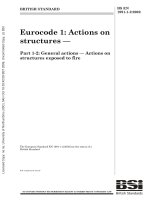
G.1 Equipment
The test machine shall be one in which an impact
force is applied approximately laterally to the rim
E.4 Criteria of acceptance
flange of a wheel complete with tyre. A suitable form
The duration of the test shall be 150 000 cycles with of
falling-weight machine is shown
M applied.
diagrammatically in Figure G.1. Alternatively, the
At completion of the test, there shall be no evidence striker may form the end of a pendulum, provided
of fatigue cracks anywhere on the wheel as
that the arm is of lightweight construction and that
indicated by a penetrant-dye test.
the striker face is horizontal at the moment of
impact with the rim.
8
Reprodu ced by I H S u n d er l i cen se wi th BSI - U n con trol l ed Copy
© BSI 07-1999
BS AU 50-2.5c:1 996
The wheel shall be mounted with its axis at 13° to where
the vertical so that its highest point is presented to
the vertically acting striker. The wheel mount shall
F is the maximum static wheel loading as
be attached to the upper surface at the mid-span of
specified by the vehicle manufacturer
a steel plate of cross section 200 mm × 25 mm
(in kg)(see B.2.1 )
having a span of 700 mm. Each end of the plate shall
G.7 Criteria of acceptance
be supported on two compression type natural
rubber mounts, in parallel, having the following
G.7.1 The wheel shall meet the conditions specified
specification:
in G.7.2 to G.7.5 .
G.7.2 There shall be no visible fractures or cracks
— hardness
50° Shore;
(other than any noted before the test) of the centre
member as indicated by penetrant-dye test.
— diameter
51 mm;
G.7.3 There shall be no separation of the centre
— uncompressed length
27 mm.
member from the rim.
The contact face of the striker shall be 150 mm wide G.7.4 There shall be no sudden total loss of tyre air
and not less than 600 mm long with a 6 mm radius pressure (i.e. the pressure shall be not less
on the long edge which contacts the wheel flange. than 90 kPa, 30 s after impact).
The mass of the wheel mount shall be 20 kg, the
G.7.5 Buckling, cracking or fracture of the rim
height shall be 230 mm and the diameter of the base flange
or general distortion of the wheel shall not, in
shall be 150 mm.
themselves, constitute a failure.
G.2 Calibration of equipment
With the wheel mount located at the mid-span of the
beam, a vertical load of 1 000 kg shall be applied to
the centre of the wheel mount as shown in Figure
G.2 The vertical central deflection of the beam shall
be 7.5 mm. For tolerance see G.8.
G.3 Procedure
The tyre selected for the test shall be either:
a) for wheels specified as original equipment, the
smallest section width size approved by the
vehicle manufacturer; or
b) the smallest nominal section width tubeless
radial-ply size specified for the rim in the edition
of BS AU 50-1.1 current at the date of production
of the wheel (as indicated in accordance
with 5.8 f).
The tyre shall be inflated to a pressure of 180 kPa.
G.4 Dropping height
The dropping height for the striker weight shall
be 230 mm above the highest part of the rim flange
in all cases.
G.8 Accuracy requirements
The accuracy of the mass of the striker, the mass of
wheel mount, and the height of drop shall be
within ± 2 %.
The accuracy of the calibration load (see G.2 ) shall
be within ± 2 % and the specified deflection during
calibration shall be within ± 10 %.
Annex H (normative)
Testing of finishing systems
H.1 Finishing systems
All finishing systems used on wheels shall
withstand the tests specified in H.2.1 , H.2.2 and
H.2.3 . These may be carried out on a test panel
(minimum size 150 mm × 100 mm) of the same
material and surface finish as used for the wheel,
except for the salt spray test (see H.2.1 ), for which it
is essential that the test is carried out on a finished
wheel.
H.2 Tests
H.2.1
Salt spray test
This test shall be carried out in accordance with
The striker shall be generally over the tyre and the BS AU 148-2:1969 to condition T 35 for a minimum
duration of 96 h, after which there shall be no
radiused edge shall overlap the rim flange
evidence of corrosion visible to the naked eye, with
by 25 mm.
the exception of highly polished surfaces where
G.6 Mass of striker
superficial corrosion shall be acceptable. The
The mass D (in kg) of the striker shall be
scratch test damage specified in 4.2.4 of
determined using the following equation:
BS AU 148-2:1969 need not be applied to the highly
D = 0.6F + 180
polished surfaces.
G.5 Alignment of striker
© BSI 07-1999
Reprodu ced by I H S u n d er l i cen se wi th BSI - U n con trol l ed Copy
9
BS AU 5 0-2.5c:1 996
Figure G.1 — Wheel impact machine
10
Reprodu ced by I H S u n d er l i cen se wi th BSI - U n con trol l ed Copy
© BSI 07- 1 999
BS AU 50-2.5c:1 996
Figure G.2 — Machine calibration method
H.2.2
Flexibility and adhesion
This test shall be carried out in accordance with
BS AU 1 48- 3: 1 969 to groups 2 and 3. On completion
of the test, there shall be no evidence of paint lifting.
H.2.3
Resistance to chipping
This test shall be carried out in accordance with
BS AU 1 48- 1 5: 1 969.
The minimum acceptance level shall be in
Annex J (informative)
Guidance on certain aspects of the
design of wheel attachment systems
J.1 Type of fixing
Although other forms of attachment may constitute
good design practice and be acceptable, these
recommendations are limited to multiple nut or bolt
attachments having spherical or conical bearing
accordance with clause 5 , assessment 2 (slight) of
and locating surfaces, or a flat bearing surface with
that standard.
parallel shank location.
© BSI 07- 1 999
Reprodu ced by I H S u n d er l i cen se wi th BSI - U n con trol l ed Copy
11
BS AU 5 0-2.5c:1 996
The transition between the threaded and
unthreaded
portions of a bolt shank or stud should
Although both centrally spigotted mountings and
non-spigotted mountings are allowed for, the former be designed to reduce stress concentrations.
is preferred.
J.3.3 Undercuts should have a 3 mm minimum
radius
at the root.
J.3 Thread data
J.3.1 Threads should be selected from:
J.2 Mounting
UNF
UNF
metric
metric
12
class 2B
(internal)
class 2a
(external)
ISO 6H
(internal)
ISO 6g
(external)
Reprodu ced by I H S u n d er l i cen se wi th BSI - U n con trol l ed Copy
J.3.2
See BS 1580-1 &
BS 1580-2
See BS 3643-2
© BSI 07-1999
BS AU 5 0-2.5 c:1 996
List of references
(see clause 5.2 )
Normative references
BSI publications
BRITISH STANDARDS INSTITUTION, London
BS 1490:1988,
Specification for aluminium and aluminium alloy ingots and castings for general
engineering purposes.
BS 2970:1989, Specification for magnesium and magnesium alloy ingots and castings.
BS AU 50, Tyres and wheels.
BS AU 50-1, Tyres.
BS AU 50-1.0:1977, General.
BS AU 50-1.1:1977, Car tyres.
BS AU 50-1.1.1:1992, Specification for sizes, loads and inflation pressures.
BS AU 50-2, Wheels and rims.
BS AU 50-2.0:1979, General (including terms and definitions, and construction and workmanship).
BS AU 50-4, Rim profiles and dimensions.
BS AU 50-4.1, Car rims.
BS AU 148, Methods of test for motor vehicle paints.
BS AU 148-2:1969, Resistance to continuous salt spray.
BS AU 148-3:1969, Flexibility and adhesion.
BS AU 148-15:1969, Resistance to chipping.
Informative references
BSI publications
BRITISH STANDARDS INSTITUTION, London
BS 1580, Specification for unified screw threads.
BS 1580-1:1962 & BS 1580-2:1962, Diameters ¼ in and larger.
BS 3643, ISO metric screw threads.
BS 3643-2:1981, Specification for selected limits of size.
BS AU 50, Tyres and wheels.
BS AU 50-2, Wheels and rims.
BS AU 50-2.6:1983, Specification for road wheels manufactured wholly or partly of light alloy for mopeds
and motor cycles.
© BSI 07-1999
Reprodu ced by I H S u n d er l i cen se wi th BSI - U n con trol l ed Copy
BS AU
5 0-2.5 c:1 996
BSI — British Standards Institution
BS I is the indep endent national b ody res p ons ib le for p rep aring
Britis h S tandards . It p res ents the UK view on s tandards in E urop e and at the
international level. It is incorp orated b y Royal C harter.
Revisions
Britis h S tandards are up dated b y amendment or revis ion. Us ers of
Britis h S tandards should make s ure that they p oss es s the latest amendments or
editions .
It is the constant aim of BS I to imp rove the quality of our p roducts and services .
We would b e grateful if anyone finding an inaccuracy or amb iguity while us ing
this Britis h S tandard would inform the S ecretary of the technical committee
res p ons ib le, the identity of which can b e found on the inside front cover.
Tel: 02 0 89 96 90 00. Fax: 02 0 89 96 7 40 0 .
BS I offers memb ers an individual up dating s ervice called PLUS which ens ures
that s ub s crib ers automatically receive the lates t editions of s tandards .
Buying standards
O rders for all BS I, international and foreign s tandards p ub lications s hould b e
addres s ed to C us tomer S ervices. Tel: 0 2 0 899 6 9 00 1 . Fax: 0 2 0 899 6 7001 .
In res p ons e to orders for international standards , it is BS I p olicy to sup p ly the
BS I imp lementation of thos e that have b een p ub lis hed as Britis h S tandards,
unless otherwis e requested.
Information on standards
BS I p rovides a wide range of information on national, E urop ean and
international standards through its Lib rary and its Technical H elp to E xp orters
S ervice. Various BS I electronic information s ervices are also availab le which give
details on all its p roducts and s ervices . C ontact the Information C entre.
Tel: 02 0 89 96 71 1 1 . Fax: 02 0 89 96 7 048.
S ub s crib ing memb ers of BS I are kep t up to date with s tandards develop ments
and receive sub s tantial discounts on the p urchase p rice of s tandards. For details
of thes e and other b enefits contact Memb ership Adminis tration.
Tel: 02 0 89 96 70 02 . Fax: 02 0 89 96 7 00 1 .
Copyright
C op yright s ub s is ts in all BS I p ub lications . BS I als o holds the cop yright, in the
UK, of the p ub lications of the internationalstandardization b odies . E xcep t as
p ermitted under the C op yright, D es igns and Patents Act 1 988 no extract may b e
rep roduced, s tored in a retrieval s ystem or transmitted in any form or b y any
means – electronic, p hotocop ying, recording or otherwis e – without p rior written
p ermis s ion from BS I.
This does not p reclude the free us e, in the cours e of imp lementing the standard,
of necess ary details such as s ymb ols, and size, typ e or grade designations. If thes e
details are to b e used for any other p urp os e than imp lementation then the p rior
written p ermiss ion of BS I must b e ob tained.
If p ermis sion is granted, the terms may include royalty p ayments or a licensing
agreement. D etails and advice can b e ob tained from the C op yright Manager.
BS I
3 89 C his wick H igh Road
London
W4 4AL
Reprodu ced by I H S u n d er l i cen se wi th BSI - U n con trol l ed Copy
Tel: 02 0 89 96 70 7 0.