Bsi bs en 00367 1992 (1999)
Bạn đang xem bản rút gọn của tài liệu. Xem và tải ngay bản đầy đủ của tài liệu tại đây (597.84 KB, 20 trang )
BRITISH STANDARD
BS EN
367:1992
Incorporating
Amendment No. 1
Protective clothing —
Protection against heat
and flames — Test
Method: Determination
of the heat
transmission on
exposure to flame
The European Standard EN 367:1992 has the status of a
British Standard
UDC 614.895.5:687.174:614.873.6:620.193.94:536.46
BS EN 367:1992
Cooperating organizations
The European Committee for Standardization (CEN), under whose supervision
this European Standard was prepared, comprises the national standards
organizations of the following countries:
Austria
Belgium
Denmark
Finland
France
Germany
Greece
Iceland
Ireland
Italy
Luxembourg
Netherlands
Norway
Portugal
Spain
Sweden
Switzerland
United Kingdom
This British Standard, having
been prepared under the
direction of the Personal
Safety Equipment Standards
Policy Committee, was published
under the authority of the
Standards Board and comes
into effect on
15 December 1992
© BSI 07-1999
The following BSI references
relate to the work on this
standard:
Committee reference PSM/35
Draft for comment 90/42481 DC
ISBN 0 580 21102 9
Oesterreichisches Normungsinstitut
Institut belge de normalisation
Dansk Standardiseringsraad
Suomen Standardisoimisliito, r.y.
Association franỗaise de normalisation
Deutsches Institut für Normung e.V.
Hellenic Organization for Standardization
Technological Institute of Iceland
National Standards Authority of Ireland
Ente Nazionale Italiano di Unificazione
Inspection du Travail et des Mines
Nederlands Normalisatie-instituut
Norges Standardiseringsforbund
Instituto Portugs da Qualidade
Asociación Espola de Normalización y Certificación
Standardiseringskommissionen i Sverige
Association suisse de normalisation
British Standards Institution
Amendments issued since publication
Amd. No.
Date
Comments
7667
May 1993 Indicated by a sideline in the margin
BS EN 367:1992
Contents
Page
Cooperating organizations
Inside front cover
National foreword
ii
Foreword
2
0 Introduction
3
1 Scope
3
2 Normative references
3
3 Definitions
3
4 Principle
4
5 Apparatus
4
6 Precautions
7
7 Sampling
7
8 Conditioning and testing atmospheres
7
9 Test procedure
7
10 Test report
9
Annex A (informative) Availability of materials
10
Annex B (normative) Reference table of electromotive force as a function
of temperature for type T (copper/copper-nickel constantan) thermocouples 11
Annex C (informative) Specimen test report form
12
Annex D (informative) Significance of the heat transfer test
12
Figure 1 — Calorimeter
4
Figure 2 — Calorimeter mounting block
5
Figure 3 — Specimen support frame
5
Figure 4 — Calorimeter location plate
6
Figure 5 — Support stand
6
Table — Reference table of electromotive force as a function of temperature
for type T (copper/copper-nickel constantan) thermocouples
11
Table D.1
13
National annex NA (informative) Committees responsible
Inside back cover
National annex NB (informative) Cross-reference
Inside back cover
© BSI 07-1999
i
BS EN 367:1992
National foreword
This British Standard has been prepared under the direction of the Personal
Safety Equipment Standards Policy Committee and is the English language
version of EN 367:1992 Protective clothing — Protection against heat and
fire —Method of determining heat transmission on exposure to flame, published
by the European Committee for Standardization (CEN).
EN 367 was produced as a result of international discussions in which the
United Kingdom took an active part.
A British Standard does not purport to include all the necessary provisions of a
contract. Users of British Standards are responsible for their correct application.
Compliance with a British Standard does not of itself confer immunity
from legal obligations.
Summary of pages
This document comprises a front cover, an inside front cover, pages i and ii,
the EN title page, pages 2 to 14, an inside back cover and a back cover.
This standard has been updated (see copyright date) and may have had
amendments incorporated. This will be indicated in the amendment table on the
inside front cover.
ii
© BSI 07-1999
EN 367
EUROPEAN STANDARD
NORME EUROPÉENNE
EUROPÄISCHE NORM
October 1992
UDC 614.895.5:687.174:614.873.6:620.193.94:536.46
Descriptors: Personal protective equipment, protective clothing, heat protection, heat resistant materials, fire resistant materials,
filing, thermal tests, heat transfer, flames, heat transfer coefficient
English version
Protective clothing — Protection against heat and flames —
Test Method: Determination of the heat transmission on
exposure to flame
Vêtements de protection — Protection contre la
chaleur et les flammes — Méthode d’essai:
Détermination de la transmission de chaleur à
l’exposition d’une flamme
Schutzkleidung — Schutz gegen Hitze und
Flammen — Prüfverfahren: Bestimmung des
Wärmedurchgangs bei Flammenwirkung
This European Standard was approved by CEN on 1992-10-01. CEN members
are bound to comply with the CEN/CENELEC Internal Regulations which
stipulate the conditions for giving this European Standard the status of a
national standard without any alteration.
Up-to-date lists and bibliographical references concerning such national
standards may be obtained on application to the Central Secretariat or to any
CEN member.
This European Standard exists in three official versions (English, French,
German). A version in any other language made by translation under the
responsibility of a CEN member into its own language and notified to the
Central Secretariat has the same status as the official versions.
CEN members are the national standards bodies of Austria, Belgium,
Denmark, Finland, France, Germany, Greece, Iceland, Ireland, Italy,
Luxembourg, Netherlands, Norway, Portugal, Spain, Sweden, Switzerland and
United Kingdom.
CEN
European Committee for Standardization
Comité Européen de Normalisation
Europäisches Komitee für Normung
Central Secretariat: rue de Stassart 36, B-1050 Brussels
© 1992 Copyright reserved to CEN members
Ref. No. EN 367:1992 E
EN 367:1992
Foreword
This European Standard was prepared by
CEN/TC 162 “Protective clothing including hand
and arm protection and lifejackets ” of which the
secretariat is held by DIN.
This European Standard shall be given the status of
a national standard, either by publication of an
identical text or by endorsement, at the latest by
April 1993, and conflicting national standards shall
be withdrawn at the latest by April 1993.
The standard was aproved and in accordance with
the CEN/CENELEC Internal Regulations, the
following countries are bound to implement this
European Standard:
Austria, Belgium, Denmark, Finland, France,
Germany, Greece, Iceland, Ireland, Italy,
Luxembourg, Netherlands, Norway, Portugal,
Spain, Sweden, Switzerland and United Kingdom.
2
© BSI 07-1999
EN 367:1992
0 Introduction
1 Scope
This method has been developed from an ASTM
method which was based on the Du Pont thermal
protective index (TPI) method. It has been
considerably modified from previous versions
following extensive interlaboratory trials carried
out by ISO/TC 94/SC 13/WG 2.
The heat transmission through clothing is largely
determined by its thickness including any air gaps
trapped between the different layers. The air gaps
can vary considerably in different areas of the same
clothing assembly. The present method provides a
grading of materials when tested under standard
test conditions.
The following major modifications have been made
from previous versions of this test method.
a) The air gap between the back of the test
specimen and the calorimeter has been
eliminated. This was found to increase all the
values recorded and to distort the results with
some materials more than others.
b) The specimen size has been increased and the
mass of the location plate has been specified. The
mass of the location plate is used to hold the
specimen in position so that the specimen is
compressed by a standard mass and is also
restricted from shrinking.
c) The method of measuring the heat
transmission has been drastically simplified and
a new term heat transfer index (HTI) has been
introduced to avoid confusion with the thermal
protective index (TPI) or other terms used in
previous versions of this test. This change makes
it easier to perform the test and reduces the
possibility of mathematical errors in calculating
the results. The heat transfer index provides a
method of grading materials which does not
imply that the material tested will give any
precise protection time under actual use
conditions.
d) Other methods of restraining the test
specimens using clamps or pins have been
rejected on the basis of interlaboratory trials
because of practical difficulties which were
believed to increase the interlaboratory
variability.
e) All terminology which implies that the test
method measures the protection time provided by
the test material has been eliminated. The
protection provided under actual use conditions
will vary considerably, depending on the severity
of the actual flame source and the thickness of the
clothing, including intermediate air gaps, in the
exposed area.
This European Standard specifies a method for
comparing the heat transmission through materials
or material assemblies used in protective clothing.
Materials are ranked by calculation of a heat
transfer index, which is an indication of the relative
protection under the specified test conditions. The
heat transfer index should not be taken as a
measure of the protection time given by the tested
materials under actual use conditions.
© BSI 07-1999
2 Normative references
This European Standard incorporates by dated or
undated reference, provisions from other
publications. These normative references are cited
at the appropriate places in the text and the
publications are listed hereafter. For dated
references, subsequent amendments to or revisions
of any of these publications apply to this European
Standard only when incorporated in it by
amendment or revision. For undated references the
latest edition of the publication referred to applies.
ISO 139, Textiles — Standard atmosphere for
conditioning and testing.
IEC 584-1, Thermocouples — Part 1: Reference
tables.
3 Definitions
For the purposes of this standard the following
definitions apply.
3.1
test specimen
all the layers of fabric or other materials arranged in
the order and orientation as used in practice and
including undergarments
3.2
incident heat flux density
the amount of energy incident per unit time on the
exposed face of the specimen, expressed in kW/m2
3.3
heat transfer index (flame)
a whole number calculated from the mean
time in seconds to achieve a temperature rise
of (24,0 ± 0,2) °C when testing by this method using
a copper disc of mass (18,00 ± 0,05) g and a starting
temperature of (25 ± 5) °C
3
EN 367:1992
4 Principle
A horizontally oriented test specimen is partially
restrained from moving and subjected to an incident
heat flux of 80 kW/m2 from the flame of a gas burner
placed beneath it. The heat passing through the
specimen is measured by means of a small copper
calorimeter on top of and in contact with the
specimen.
The time to record a temperature rise
of (24,0 ± 0,2) °C in the calorimeter is recorded in
seconds. The mean result for three test specimens is
calculated as the “heat transfer index (flame)”.
5 Apparatus
The apparatus consists of:
— a gas burner;
— a copper disc calorimeter;
— a specimen support frame;
— a calorimeter location plate;
— a support stand;
— suitable measuring equipment;
— a template.
5.1 Gas burner. A flat topped Meker burner with a
perforated top area of (38 ± 2) mm diameter and a
jet suitable for propane gas shall be used.
Commercial grade propane shall be used with the
flow being controlled by a fine control valve and
flowmeter.
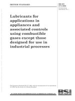
5.2 Copper disc calorimeter. The calorimeter
consists of a disc of copper of at least 99 % purity,
having a diameter of 40 mm and thickness 1,6 mm,
and a weight of 18 g. The disc should be accurately
weighed before assembly.
A copper-constantan thermocouple, with an output
in millivolts complying with IEC 584-1, is mounted
on the copper disc as shown in Figure 1. The
constantan wire should be attached to the centre of
the disc and the copper wire should be attached as
near the circumference as possible but so as not to
interfere with mounting the disc in the block. The
diameter of both wires should be 0,26 mm or less
and only the length attached to the disc should be
bared.
The calorimeter is located in a mounting block
which shall consist of a 89 mm diameter circular
piece of asbestos-free non combustible, heat
insulating board of nominal thickness 13 mm. The
thermal characteristics should comply with the
following specification:
— density:
(750 ± 50) kg/m3
— thermal conductivity: 0,18 W/(m·k) ± 10 %
4
Figure 1 — Calorimeter
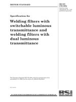
A circular cavity is machined in the centre of the
block to accommodate the disc and an air gap, as
shown in Figure 2. The disc is bonded in position
around its circumference with an adhesive capable
of withstanding temperatures of about 200 °C. The
face of the copper disc shall be flush with the surface
of the mounting block. It shall also be coated with a
thin layer of an optically black paint having a
coefficient of absorption, a, greater than 0,9
(see Annex A ).
5.3 Specimen support frame. The specimen support
frame consists of a piece of copper 150 mm square
and 1,6 mm thick with a 50 mm square hole in its
centre (see Figure 3).
5.4 Calorimeter location plate. The calorimeter
location plate is made from a piece of
aluminium 149 mm square and 6 mm thick A
circular hole 90 mm in diameter shall be centrally
in this block (see Figure 4). The plate shall
weigh (264 ± 13) g.
5.5 Support stand. A support stand is used to locate
the specimen support frame relative to the burner.
The top face of the specimen support frame should
be 50 mm above and parallel with the top face of the
burner with the axis of the burner aligned with the
centre of the opening in the support frame
(see Figure 5).
© BSI 07-1999
EN 367:1992
Figure 2 — Calorimeter mounting block
Figure 3 — Specimen support frame
© BSI 07-1999
5
EN 367:1992
Figure 4 — Calorimeter location plate
Figure 5 — Support stand
6
© BSI 07-1999
EN 367:1992
It is convenient to have a shutter between the
burner and the specimen support frame. The
shutter should open completely in less than 0,2 s
and should be operated immediately after placing
the burner in position. It is useful if the positioning
of the burner, or the opening of the shutter, if fitted,
can be used to record the start of the exposure
automatically.
5.6 Recorder. To enable the absolute temperature of
the copper disc to be determined, the thermocouple
should be connected to either an ice junction or a
commercial reference junction. The voltage signal
from the thermocouple should be connected to either
a suitable potentiometric chart recorder or
programmable data recorder. The recorder should
enable voltages to be read to 10 4V and times
to 0,2 s.
5.7 Template. A flat rigid template
measuring 140 mm × 140 mm.
6 Precautions
a) Perform the test in a hood or ventilated area to
carry away the fumes. It may be necessary to turn
off the exhaust or to shield the apparatus during
the test so as not to disturb the flame.
b) The equipment becomes hot during testing and
some test materials may melt or drip. Use
protective gloves when handling hot objects.
c) Keep combustible materials away from the
burner. Ensure that the solvent used for cleaning
the calorimeter is kept away from hot surfaces
and naked flames.
7 Sampling
7.1 Specimen dimensions
The specimens shall have the
dimensions 140 mm × 140 mm and shall be taken
from points more than 50 mm from the edge of the
pieces of the material, in an area free from defects.
Composite specimens shall reproduce the
arrangement in which the layers are used in
practice.
The specimen shall be marked out using the
template (see 5.7 ).
8 Conditioning and testing
atmospheres
8.1 Conditioning atmosphere
Prior to testing, the specimens shall be conditioned
for at least 24 h at a temperature of (20 ± 2) °C and
a relative humidity of (65 ± 2) % (see ISO 139). If
testing is not carried out immediately after
conditioning, place the conditioned test specimens
in a sealed container. Begin testing of each
specimen within 3 min of removing it from the
conditioning atmosphere or sealed container.
8.2 Testing atmosphere
Perform the tests in an atmosphere having a
temperature of 10 °C to 30 °C and a relative
humidity of 15 % to 80 % and which is free from
draughts.
9 Test procedure
9.1 Preparation and calibration
9.1.1 Preliminary measures
Position the support frame on the support stand so
that the top surface on which the specimen is placed
is 50 mm above the top face of the burner. It is
suggested that a guide and stops be used to enable
the burner to be positioned quickly with its axis in
line with the centre of the specimen.
Place the burner to one side, activate and ignite the
gas supply, and allow several minutes for flame
stabilization.
Connect the thermocouple to the cold junction, and
connect the output voltage into the recording device.
Before every incident heat flux density regulation or
specimen evaluation, the copper disc temperature
should be in relatively steady state and
within ± 2 °C of ambient temperature. Cooling may
be accelerated by the use of any dry, chilled heat
sink, or by forced air draft. Alternatively, a number
of calorimeter units may be rotated. Heating may be
achieved by contact of the palm of the hand with the
copper disc or by short exposure to the burner flame.
NOTE On no account should the calorimeter mounting block be
allowed to come into contact with water. If this occurs
accidentally it should be dried out thoroughly before further use.
7.2 Number of specimens
A minimum of three specimens shall be tested for
each material or assembly of materials.
© BSI 07-1999
7
EN 367:1992
9.1.2 Regulation of the incident heat flux
density
The gas flow rate and burner setting will vary with
the individual combination used, and regulation of
the settings for one or both will be necessary during
initial installation and from time to time during
testing. The correct flux should be achieved from a
flame with clearly defined stable light blue cones
firmly positioned on the burner grid with a large
diffuse bluish flame above.
The flame setting is confirmed by measuring the
heat flux density with the calorimeter.
Place the calorimeter location plate on the specimen
support frame. Place the calorimeter in the hole in
the locating plate with the copper disc facing
downwards.
Select the required rate of travel of the recording
device, and slide the burner quickly and deliberately
under the calorimeter until it locates against its
stops. If a shutter is used, open the shutter (see 5.5 ).
Allow the burner to remain in position for
about 10 s.
Withdraw the burner or close the shutter.
The recorded output should show a short non-linear
temperature-time region just after the start of the
exposure, followed by a linear region which
continues until exposure ceases. Refer to standard
thermocouple electromotive force tables to
determine the rate of rise of temperature in degrees
celsius per second of this linear region. The heat flux
density, Q, (in kW/m2 ) is then determined from the
following equation:
M Cp R
Q=
A
where
M is the mass of the copper disc in kg;
Cp is the specific heat of the
copper 0,385·(kJ/kg °C);
R is the rate of rise in disc temperature in
linear region in °C/s;
A is the disc area in m2 .
⋅
⋅
The heat flux density determined by this procedure
should be within ± 5 % of the specified 80 kW/m2 .
Adjust the gas flow rate if required, and repeat until
three consecutive values are obtained which fall
within the required limits.
9.2 Test specimen mounting
9.2.1 Place the outermost layer of the specimen face
downwards on the specimen support frame (see 5.3 ).
Place the location plate (see 5.4) on top of the
9.2.2 If the specimen consists of more than one layer
and the layers are not attached to one another,
remove the location plate and mount each
successive layer in the order and orientation as used
in the assembly. Use the weight of the location
plate, with no additional pressure, to press each
layer into contact with the previous layer.
9.2.3 After the last (innermost) layer has been
mounted, replace the location plate and place the
calorimeter in the hole in the location plate so that
the copper disc is in contact with the top of the
innermost layer.
9.3 Test specimen exposure
9.3.1 Slide the burner quickly and deliberately into
position. Immediately move the shutter, if fitted,
from below the specimen. Start the recording device
simultaneously with the exposure of the specimen to
the burner flame or mark the start of the exposure
with the recorder already running, depending on the
equipment used.
9.3.2 Allow the test to continue until a temperature
rise of (24 ± 0,2) °C is observed. Observe and note
any changes in specimen appearance during the
test, e.g. shrinkage, scorching, charring, holing,
glowing, melting or dripping. Replace the shutter, if
fitted, and withdraw the burner Switch off the
recorder
9.3.3 Remove the calorimeter and clean off any
combustion products whilst it is still hot (see 6.2 ).
Cool to within ± 2 °C of ambient temperature.
If the remaining deposit on the calorimeter is thick
or uneven, if the black coating has deteriorated, or if
the copper is exposed, the calorimeter disc should be
cleaned (see Annex A ) and repainted (see 5.2 ). At
least one calibration run (see 9.1.2 ) should be
carried out with the recoated calorimeter before
testing further specimens.
9.3.4 Measure the time in seconds for a
temperature rise in the calorimeter
of (24,0 ± 0,2) °C (see Annex D ).
9.3.5 Repeat the procedure with two more
specimens. Calculate the heat transfer index as the
mean of the times for (24 ± 2) °C rise, to the nearest
whole number.
NOTE It is also possible to measure the time in seconds for a
temperature rise of (12,0 ± 0,1) °C, corresponding to a
thermocouple output increase of 0,5 mV using an 18,00 g
calorimeter. This measurement can be used to determine to what
extent heat transfer is delayed or reduced. However, it should be
stressed that the times measured have only a limited accuracy
and do not necessarily relate to protection times under actual use
conditions.
specimen.
8
© BSI 07-1999
EN 367:1992
10 Test report
The test report shall contain the following
particulars:
a) name of test laboratory;
b) date;
c) reference to this standard;
d) identification reference of the materials tested;
e) description of the test materials and the
arrangement in which they were tested, if
possible details of generic names, mass per unit
area and thickness under no pressure and under
the pressure of the location plate should be given;
f) the time in seconds for a 24 °C temperature rise
for each specimen tested and the heat transfer
index calculated from these individual results;
g) if requested, the time in seconds for a 12 °C
temperature rise for each specimen tested may
also be reported;
h) description of any changes in appearance of the
specimens;
i) a statement as follows: “These results have
been obtained by a test method intended solely to
rank the material and are not necessarily
applicable to actual fire conditions”.
© BSI 07-1999
9
EN 367:1992
Annex A (informative)
Availability of materials
The following are examples of sources of materials specified in this standard. Equally suitable alternatives
are available from other sources. This information is given for the convenience of users of this standard and
does not constitute an endorsement by CEN of these products.
Gas burner (clause 5.1 )
Fisher Burner model 3-902 P.
Fisher Scientific 60
Hottingerstraße 14
8032 Zurich, Switzerland
Insulating board (clause 5.2 )
Monolux 500.
Cape Boards & Panels Ltd.
Iver Lane, Uxbridge UB 80 2JQ,
England
Black paint (clause 5.2 )
Nextel Velvet Coating Black 2010.
3M UK Ltd. P.O. Box 38, Yeoman House,
63, Croydon Road, Penge, London SE20 7TR,
England
Calorimeter cleaning liquid (clause 9.3.3 )
A mixture of three parts 1.1.1 trichloroethane and one part ethanol by volume has been found
suitable.
Calorimeter paint remover (clause 9.3.3 )
Acetone.
10
© BSI 07-1999
EN 367:1992
Annex B (normative)
Reference table of electromotive force as a function of temperature for type T
(copper/copper-nickel constantan) thermocouples
(extracted from IEC Publication 584-1, 1977)
Type T Copper/Copper-Nickel (constantan)
Electromotive force as a function of temperature
E 4V
t68 ° C
0
1
2
3
4
5
6
7
8
9
t 68 ° C
0
0
39
78
117
156
195
234
273
312
351
0
10
391
430
470
510
549
589
629
669
709
749
10
20
789
830
870
911
951
992
1 032
1 073
1 114
1 155
20
30
1 196
1 237
1 279
1 320
1 361
1 403
1 444
1 486
1 528
1 569
30
40
1 611
1 653
1 695
1 738
1 780
1 822
1 865
1 907
1 950
1 992
40
50
2 035
2 078
2 121
2 164
2 207
2 250
2 294
2 337
2 380
2 424
50
60
2 467
2 511
2 555
2 599
2 643
2 687
2 731
2 775
2 819
2 864
60
70
2 908
2 953
2 997
3 042
3 087
3 131
3 176
3 221
3 266
3 312
70
80
3 357
3 402
3 447
3 493
3 538
3 584
3 630
3 676
3 721
3 767
80
90
3 813
3 859
3 906
3 952
3 998
4 044
4 091
4 137
4 184
4 231
90
100
4 277
4 324
4 371
4 418
4 465
4 512
4 559
4 607
4 654
4 701
100
110
4 749
4 796
4 844
4 891
4 939
4 987
5 035
5 083
5 131
5 179
110
120
5 227
5 275
5 324
5 372
5 420
5 469
5 517
5 566
5 615
5 663
120
130
5 712
5 761
5 810
5 859
5 908
5 957
6 007
6 056
6 105
6 155
130
140
6 204
6 254
6 303
6 353
6 403
6 452
6 502
6 552
6 602
6 652
140
150
6 702
6 753
6 803
6 853
6 903
6 954
7 004
7 055
7 106
7 156
150
160
7 207
7 258
7 309
7 360
7 411
7 462
7 513
7 564
7 615
7 666
160
170
7 718
7 769
7 821
7 872
7 924
7 975
8 027
8 079
8 131
8 183
170
180
8 235
8 287
8 339
8 391
8 443
8 495
8 548
8 600
8 652
8 705
180
190
8 757
8 810
8 863
8 915
8 968
9 021
9 074
9 127
9 180
9 233
190
200
9 286
9 339
9 392
9 446
9 499
9 553
9 606
9 659
9 713
9 767
200
210
9 820
9 874
9 928
9 982
10 036
10 090
10 144
10 198
10 252
10 306
210
220
10 360
10 414
10 469
10 532
10 578
10 632
10 687
10 741
10 796
10 851
220
230
10 905
10 960
11 015
11 070
11 125
11 180
11 235
11 290
11 345
11 401
230
240
11 456
11 511
11 566
11 622
11 677
11 733
11 788
11 844
11 900
11 956
240
250
12 011
12 067
12 123
12 179
12 235
12 291
12 347
12 403
12 459
12 515
250
260
12 572
12 628
12 684
12 741
12 797
12 854
12 910
12 967
13 024
13 080
260
270
13 137
13 194
13 251
13 307
13 364
13 421
13 478
13 535
13 592
13 650
270
280
13 707
13 764
13 821
13 879
13 936
13 993
14 051
14 108
14 166
14 223
280
290
14 281
14 339
14 396
14 454
14 512
14 570
14 628
14 686
14 744
14 802
290
© BSI 07-1999
11
EN 367:1992
Annex C (informative)
Specimen test report form
Tests carried out by EN 367
Test Laboratory
Reference No
Test materials
Date
Type
Mass/unit area
g/m 2
Layer 1 (outer)
2
3
4
5
Test results
Incident heat flux
Specimen 1
Specimen 2
Specimen 3
Thickness mm
no pressure
Under location plate
kW/m 2
Time to 24 °C temperature
rise
Heat transfer index
Observations on specimen appearance.
These results have been obtained by a test method aimed solely at ranking the materials tested and are
not necessarily applicable to actual fire conditions.
Annex D (informative)
Significance of the heat transfer test
The heat transfer index (HTI) provides a method of ranking the ability of clothing assemblies to delay
the transfer of heat from a flame. It is derived from the time in seconds to achieve a 24 °C temperature
rise under the specified test conditions, which corresponds to a thermocouple output increase
of 1,00 mV ± 0,01 mV (± 10 4V) and a total heat transfer of (132,3 ± 1,1) kJ/m2 .
The heat transfer through clothing is dependent on the thickness of the clothing assembly including any
air gaps. The HTI is determined with the specimen compressed under a standard load so as to minimize
any air gaps. Thicker clothing gives better protection and gives higher HTI values but with increased
variability.
The heat transfer index (HTI) should not be regarded as the time for which the clothing will provide
protection against a flame. Under actual use conditions, the severity of the flame and the compression of
the clothing are not constant and can vary considerably from the standard test conditions. The performance
of wet clothing may differ from the performance of the dry test specimen.
An interlaboratory trial was carried out in 1989 testing 18 single or multilayer assemblies in five
laboratories. A further interlaboratory trial in 1991 involved seven single or multilayer assemblies tested
in seven different laboratories. The following formulae for repeatability and reproducibility were derived
from this latest trial:
repeatability
= 0,19 + 0,055 (mean)
reproducibility
= 1,21 + 0,12 (mean)
12
© BSI 07-1999
EN 367:1992
The performance of the materials tested in these trials could be divided into five bands, as shown in the
following Table D.1.
This table illustrates how adding extra layers increases the HTI value. Thick materials, particularly those
containing large volumes of entrapped air, are especially effective. The suggested limits for the different
bands are based on the performance of actual materials and allow for the variability between laboratories.
The mid-points of each band are based on frequently occurring values and the band widths are twice the
reproducibility based on this midpoint value. If performance levels are set too close to the formal value,
different laboratories will give different classifications.
In this proposed classification, any test assembly giving results which fall on the limit of a particular band
ought to be retested and classification based on a minimum of two sets of results falling within the same
band. Assemblies which give results which differ by less than the reproducibility for the band should not be
regarded as being significantly different. It is possible to determine the heat transfer index (HTI) (24–12)
as an additional factor in order to distinguish between different materials. However, this parameter is also
subject to poor reproducibility and to rounding errors.
1
Band
HTI limits
Typical assembly
Table D.1
3 to 6
Single layer
2
7 to 12
Double layer, thick single
3
13 to 20
Triple layer, thick double
4
5
21 to 30
over 31
Very thick
Extremely thick
© BSI 07-1999
Comments
Most single layer fabrics give
results of 4 or 5
Covers a wide range of normal
multilayer apparel
Specialist firefighting clothing has
HTI about 16
Specialist heat protective clothing
Very special applications
Reproducibility
1,7
2,3
3,2
4,3
13
14
blank
BS EN 367:1992
National annex NA (informative)
Committees responsible
The United Kingdom participation in the preparation of this European Standard was entrusted by the
Personal Safety Equipment Standards Policy Committee (PSM/-) to Technical Committee PSM/35 upon
which the following bodies were represented:
Amalgamated Engineering Union
British Clothing Industry Association
British Foundry Association
British Leather Confederation
British Railways Board
British Steel plc
British Textile Confederation
British Textile Technology Group
Chemical Industries’ Association
Chief and Assistant Chief Fire Officers’ Association
Confederation of British Wool Textiles Limited
Health and Safety Executive
Home Office
Industrial Safety (Protective Equipment) Manufacturers’ Association
Institute of Occupational Hygienists
Institute of Purchasing and Supply
Institution of Fire Engineers
International Wool Secretariat
Lambeg Industrial Research Association
Medical Research Council
Ministry of Defence
Society of British Gas Industries
Trades Union Congress
National annex NB (informative)
Cross-reference
Publication referred to Corresponding British Standard
ISO 139:1973
BS 1051:1981 Glossary of terms relating to the conditioning, testing and mass
determination of textiles
© BSI 07-1999
BS EN
367:1992
BSI — British Standards Institution
BSI is the independent national body responsible for preparing
British Standards. It presents the UK view on standards in Europe and at the
international level. It is incorporated by Royal Charter.
Revisions
British Standards are updated by amendment or revision. Users of
British Standards should make sure that they possess the latest amendments or
editions.
It is the constant aim of BSI to improve the quality of our products and services.
We would be grateful if anyone finding an inaccuracy or ambiguity while using
this British Standard would inform the Secretary of the technical committee
responsible, the identity of which can be found on the inside front cover.
Tel: 020 8996 9000. Fax: 020 8996 7400.
BSI offers members an individual updating service called PLUS which ensures
that subscribers automatically receive the latest editions of standards.
Buying standards
Orders for all BSI, international and foreign standards publications should be
addressed to Customer Services. Tel: 020 8996 9001. Fax: 020 8996 7001.
In response to orders for international standards, it is BSI policy to supply the
BSI implementation of those that have been published as British Standards,
unless otherwise requested.
Information on standards
BSI provides a wide range of information on national, European and
international standards through its Library and its Technical Help to Exporters
Service. Various BSI electronic information services are also available which give
details on all its products and services. Contact the Information Centre.
Tel: 020 8996 7111. Fax: 020 8996 7048.
Subscribing members of BSI are kept up to date with standards developments
and receive substantial discounts on the purchase price of standards. For details
of these and other benefits contact Membership Administration.
Tel: 020 8996 7002. Fax: 020 8996 7001.
Copyright
Copyright subsists in all BSI publications. BSI also holds the copyright, in the
UK, of the publications of the internationalstandardization bodies. Except as
permitted under the Copyright, Designs and Patents Act 1988 no extract may be
reproduced, stored in a retrieval system or transmitted in any form or by any
means – electronic, photocopying, recording or otherwise – without prior written
permission from BSI.
This does not preclude the free use, in the course of implementing the standard,
of necessary details such as symbols, and size, type or grade designations. If these
details are to be used for any other purpose than implementation then the prior
written permission of BSI must be obtained.
BSI
389 Chiswick High Road
London
W4 4AL
If permission is granted, the terms may include royalty payments or a licensing
agreement. Details and advice can be obtained from the Copyright Manager.
Tel: 020 8996 7070.