Bsi bs en 00817 2008 (2009)
Bạn đang xem bản rút gọn của tài liệu. Xem và tải ngay bản đầy đủ của tài liệu tại đây (1.06 MB, 54 trang )
Licensed copy: The University of Hong Kong, The University of Hong Kong, Version correct as of 18/04/2009 01:54, (c)
BSI
BRITISH STANDARD
Sanitary tapware —
Mechanical mixing
valves (PN 10) —
General technical
specifications
ICS 91.140.70,
NO COPYING WITHOUT BSI PERMISSION EXCEPT AS PERMITTED BY COPYRIGHT LAW
BS EN 817:2008
Incorporating
Corrigendum
January 2009
Licensed copy: The University of Hong Kong, The University of Hong Kong, Version correct as of 18/04/2009 01:54, (c)
BSI
BS EN 817:2008
National foreword
This British Standard is the UK implementation of EN 817:2008. It
supersedes BS EN 817:1998 and which is withdrawn.
The UK participation in its preparation was entrusted to Technical
Committee B/504/8, Sanitary tapware.
A list of organizations represented on this committee can be obtained on
request to its secretary.
This publication does not purport to include all the necessary provisions
of a contract. Users are responsible for its correct application.
Compliance with a British Standard cannot confer immunity
from legal obligations.
This British Standard
was published under the
authority of the
Standards Policy and
Strategy Committee on 31
December 2008
© BSI 2009
ISBN 978 0 580 66666 7
Amendments/corrigenda issued since publication
Date
Comments
31 January 2009
Correction to low resolution images
Licensed copy: The University of Hong Kong, The University of Hong Kong, Version correct as of 18/04/2009 01:54, (c)
BSI
BS EN 817:2008
EUROPEAN STANDARD
EN 817
NORME EUROPÉENNE
EUROPÄISCHE NORM
June 2008
ICS 91.140.70
Supersedes EN 817:1997
English Version
Sanitary tapware - Mechanical mixing valves (PN 10) - General
technical specifications
Robinetterie sanitaire - Mitigeurs mécaniques (PN 10) Spécifications techniques générales
Sanitärarmaturen - Mechanisch einstellbare Mischer (PN
10) - Allgemeine technische Spezifikation
This European Standard was approved by CEN on 29 May 2008.
CEN members are bound to comply with the CEN/CENELEC Internal Regulations which stipulate the conditions for giving this European
Standard the status of a national standard without any alteration. Up-to-date lists and bibliographical references concerning such national
standards may be obtained on application to the CEN Management Centre or to any CEN member.
This European Standard exists in three official versions (English, French, German). A version in any other language made by translation
under the responsibility of a CEN member into its own language and notified to the CEN Management Centre has the same status as the
official versions.
CEN members are the national standards bodies of Austria, Belgium, Bulgaria, Cyprus, Czech Republic, Denmark, Estonia, Finland,
France, Germany, Greece, Hungary, Iceland, Ireland, Italy, Latvia, Lithuania, Luxembourg, Malta, Netherlands, Norway, Poland, Portugal,
Romania, Slovakia, Slovenia, Spain, Sweden, Switzerland and United Kingdom.
EUROPEAN COMMITTEE FOR STANDARDIZATION
COMITÉ EUROPÉEN DE NORMALISATION
EUROPÄISCHES KOMITEE FÜR NORMUNG
Management Centre: rue de Stassart, 36
© 2008 CEN
All rights of exploitation in any form and by any means reserved
worldwide for CEN national Members.
B-1050 Brussels
Ref. No. EN 817:2008: E
Licensed copy: The University of Hong Kong, The University of Hong Kong, Version correct as of 18/04/2009 01:54, (c)
BSI
BS EN 817:2008
EN 817:2008 (E)
Contents
page
Foreword..............................................................................................................................................................6
Introduction .........................................................................................................................................................7
1
Scope ......................................................................................................................................................8
2
Normative references ..........................................................................................................................10
3
3.1
3.2
Terms, definitions and designation ...................................................................................................10
Terms and definitions .........................................................................................................................10
Designation ..........................................................................................................................................11
4
4.1
4.2
Marking and identification ..................................................................................................................11
Marking .................................................................................................................................................11
Identification.........................................................................................................................................12
5
5.1
5.2
Materials ...............................................................................................................................................12
Chemical and hygiene requirements .................................................................................................12
Exposed surface conditions...............................................................................................................12
6
6.1
6.2
6.3
6.4
6.5
6.6
6.7
Dimensional characteristics ...............................................................................................................12
General remarks...................................................................................................................................12
Inlet dimensions...................................................................................................................................12
Outlet dimensions................................................................................................................................17
Mounting dimensions..........................................................................................................................19
Special cases .......................................................................................................................................20
Flexible hoses for shower outlets......................................................................................................20
Shower outlets .....................................................................................................................................20
7
Sequence of testing.............................................................................................................................21
8
8.1
8.2
8.3
8.4
8.5
8.6
8.7
Leaktightness characteristics ............................................................................................................21
General..................................................................................................................................................21
Test methods........................................................................................................................................21
Leaktightness of the obturator and of the mixing valve upstream of the obturators with the
obturator in the closed position.........................................................................................................22
Leaktightness of the mixing valve downstream of the obturator with the obturator open .........22
Leaktightness of manually operated diverter ...................................................................................22
Leaktightness and operation of diverter with automatic return .....................................................23
Leaktightness of the obturator: cross flow between hot water and cold water............................24
9
9.1
9.2
9.3
9.4
9.5
Pressure resistance characteristics – mechanical performance under pressure ........................26
General..................................................................................................................................................26
Principle................................................................................................................................................26
Apparatus .............................................................................................................................................26
Mechanical behaviour upstream of the obturator – obturator in the closed position..................26
Mechanical behaviour downstream of the obturator – obturator in the open position ...............26
10
10.1
10.2
10.3
10.4
10.5
10.6
10.7
Hydraulic characteristics ....................................................................................................................27
General..................................................................................................................................................27
Initial settings.......................................................................................................................................27
Principle................................................................................................................................................28
Apparatus .............................................................................................................................................28
Procedure .............................................................................................................................................28
Determination of flow rate ..................................................................................................................29
Determination of sensitivity................................................................................................................30
11
Mechanical strength characteristics - torsion test for operating mechanism ..............................33
2
Licensed copy: The University of Hong Kong, The University of Hong Kong, Version correct as of 18/04/2009 01:54, (c)
BSI
BS EN 817:2008
EN 817:2008 (E)
11.1
11.2
General..................................................................................................................................................33
Test method .........................................................................................................................................33
12
12.1
12.2
12.3
Mechanical endurance characteristics..............................................................................................34
Mechanical endurance of the control device....................................................................................34
Mechanical endurance of diverters ...................................................................................................38
Mechanical endurance of swivel spouts ...........................................................................................40
13
Backflow protection ............................................................................................................................41
14
14.1
14.2
14.3
Acoustic characteristics .....................................................................................................................41
General..................................................................................................................................................41
Procedure .............................................................................................................................................41
Requirements.......................................................................................................................................41
Annex A (informative) Apparatus ..................................................................................................................43
Annex B (informative) Pressure take-off tee.................................................................................................47
Bibliography ......................................................................................................................................................50
www.bzfxw.com
3
Licensed copy: The University of Hong Kong, The University of Hong Kong, Version correct as of 18/04/2009 01:54, (c)
BSI
BS EN 817:2008
EN 817:2008 (E)
Figures
Figure 1
Supply system with a pressure range of (0,05 to 1,0) MPa [(0,5 to 10) bar].............................9
Figure 2
Flexible hoses and plain tube .....................................................................................................14
Figure 3
Multi-hole mechanical mixing valve ...........................................................................................15
Figure 4
Supply connections for mechanical mixing valve and remote outlets ..................................16
Figure 5
Remote outlet ...............................................................................................................................18
Figure 6
Single hole mechanical mixing valve.........................................................................................18
Figure 7
Two hole mechanical mixing valve ............................................................................................18
Figure 8
Single hole mechanical mixing valve.........................................................................................19
Figure 9
Two hole mechanical mixing valve ............................................................................................20
Figure 10
Sensitivity curve...........................................................................................................................31
Figure 11
Radius for the determination of sensitivity ...............................................................................32
Figure 12
Rectangular movement ...............................................................................................................34
Figure 13
Triangular movement...................................................................................................................35
Figure 14
Test bench adjustment torque for conventionnal mixing valve..............................................37
Figure 15
Test bench adjustment torque for joystick mixing valve.........................................................37
Figure 16
Test bench adjustment torque for sequential mixing valve ....................................................37
www.bzfxw.com
Figure A 1
Supply circuits ........................................................................................................................43
Figure A 2
Test circuit...............................................................................................................................45
Figure A 3
Mounting of the mixing valve ................................................................................................46
Figure B 1
Pressure take-off tee ..............................................................................................................47
Figure B 2
Schematic examples of pressure take-off tees ...................................................................48
4
Licensed copy: The University of Hong Kong, The University of Hong Kong, Version correct as of 18/04/2009 01:54, (c)
BSI
BS EN 817:2008
EN 817:2008 (E)
Tables
Table 1 Conditions of use/Classifications........................................................................................................8
Table 2 Designation ..........................................................................................................................................11
Table 3 Inlet dimensions (mechanical mixing valve).....................................................................................13
Table 4 Outlet dimensions (Remote outlets, mechanical mixing valve) .....................................................17
Table 5 Mounting dimensions (Outlets, single- and multi-hole mechanical mixing valve).......................19
Table 6 Test Sequence .....................................................................................................................................21
Table 7 Summary of leaktightness tests ........................................................................................................25
Table 8 Summary of pressure resistance characteristic tests.....................................................................27
Table 9 Initial Settings ......................................................................................................................................27
Table 10
Flow rates according to application...........................................................................................29
Table 11
Performance levels ......................................................................................................................30
Table 12
Summary of test conditions for cartridges ...............................................................................35
Table 13
Summary of test conditions for diverters..................................................................................39
Table 14
Flow rate classes (EN ISO 3822-4 Annex A)..............................................................................41
Table 15
Acoustic group.............................................................................................................................42
Table A 1
Connecting dimension ................................................................................................................45
Table B 1
Dimensions of the pressure take-off tee ...................................................................................47
www.bzfxw.com
5
Licensed copy: The University of Hong Kong, The University of Hong Kong, Version correct as of 18/04/2009 01:54, (c)
BSI
BS EN 817:2008
EN 817:2008 (E)
Foreword
This document (EN 817:2008) has been prepared by Technical Committee CEN/TC 164 “Water supply”, the
secretariat of which is held by AFNOR.
This European Standard shall be given the status of a national standard, either by publication of an identical text or
by endorsement, at the latest by December 2008, and conflicting national standards shall be withdrawn at the latest
by December 2008.
Attention is drawn to the possibility that some of the elements of this document may be the subject of patent rights.
CEN [and/or CENELEC] shall not be held responsible for identifying any or all such patent rights.
This document supersedes EN 817:1997.
This European Standard acknowledges the field of application for mechanical mixing valves used in water supply
systems with a pressure range of (0,05 to 1,0) MPa (0,5 bar to 10 bar).
According to the CEN/CENELEC Internal Regulations, the national standards organizations of the following
countries are bound to implement this European Standard: Austria, Belgium, Bulgaria, Cyprus, Czech Republic,
Denmark, Estonia, Finland, France, Germany, Greece, Hungary, Iceland, Ireland, Italy, Latvia, Lithuania,
Luxembourg, Malta, Netherlands, Norway, Poland, Portugal, Romania, Slovakia, Slovenia, Spain, Sweden,
Switzerland and the United Kingdom.
www.bzfxw.com
6
Licensed copy: The University of Hong Kong, The University of Hong Kong, Version correct as of 18/04/2009 01:54, (c)
BSI
BS EN 817:2008
EN 817:2008 (E)
Introduction
In respect of potential adverse effects on the quality of water intended for human consumption, caused by the
product covered by this European Standard.
This European Standard provides no information as to whether the product can be used without restriction in any of
the Member States of the EU or EFTA.
It should be noted that, while awaiting the adoption of verifiable European criteria, existing national regulations
concerning the use and/or the characteristics of these products remain in force.
This document identifies characteristics and technical requirements for mechanical mixing valves.
www.bzfxw.com
7
Licensed copy: The University of Hong Kong, The University of Hong Kong, Version correct as of 18/04/2009 01:54, (c)
BSI
BS EN 817:2008
EN 817:2008 (E)
1
Scope
This European Standard specifies:
the dimensional, leaktightness, pressure resistance, hydraulic performance, mechanical strength, endurance
and acoustic characteristics with which mechanical mixing valves need to comply;
test methods to verify the characteristics.
The tests described in this European Standard are type tests (laboratory tests) and not quality control tests carried
out during manufacture.
This European Standard applies to PN 10 mechanical mixing valves for use with sanitary appliances installed in
rooms used for bodily hygiene (cloakrooms, bathrooms, etc.) and in kitchens, i.e. for use with baths, wash basins,
bidets, showers and sinks.
The conditions of use and classifications are given in 0.
Table 1 — Conditions of use/classifications
Water supply
system
Pressure
Temperature
a
NOTE
8
Operating range of mechanical mixing
valves
Limits
Dynamic pressure
> 0,05 MPa
(0,5 bar)
Static pressure
≤ 1,0 MPa
(10,0 bar)
≤ 90 °C
Recommended
Flow rate
classes
Acoustics
Marking
See 0
See Clause 14
See Clause 4
Z ≤ 0,15 l/s
A ≤ 0,25 l/s
S ≤ 0,33 l/s
B ≤ 0,42 l/s
C ≤ 0,50 l/s
D ≤ 0,63 l/s
for example
IA
IIC / B
www.bzfxw.com
Dynamic pressure
(0,1 to 0,5) MPa
[(1,0 to 5,0) bar]
Group I -
Group II –
unclassified
I /- a
II /- a
≤ 65 °C
Without flow rate class: mechanical mixing valves without interchangeable outlet accessories are tested with the original
outlet accessories of the manufacturer and are not marked with a flow rate class.
Mechanical mixing valves for use at pressures lower than those in Table 1 are covered by EN 1286.
Licensed copy: The University of Hong Kong, The University of Hong Kong, Version correct as of 18/04/2009 01:54, (c)
BSI
BS EN 817:2008
EN 817:2008 (E)
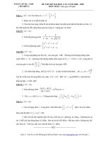
Key
1
2
cold water
hot water
3
4
mains supply pipe (supply pressures up to 10 bar)
water heater
Figure 1 — Supply system with a pressure range of (0,05 to 1,0) MPa [(0,5 to 10) bar]
9
Licensed copy: The University of Hong Kong, The University of Hong Kong, Version correct as of 18/04/2009 01:54, (c)
BSI
BS EN 817:2008
EN 817:2008 (E)
2
Normative references
The following referenced documents are indispensable for the application of this document. For dated references,
only the edition cited applies. For undated references, the latest edition of the referenced document (including any
amendments) applies.
EN 246, Sanitary tapware — General specifications for flow rate regulators
EN 248, Sanitary tapware — General specification for electrodeposited coatings of Ni-Cr
EN 1112, Sanitary tapware – Shower outlets for sanitary tapware for water supply systems of type 1 and type 2 –
General technical specification
EN 1113, Sanitary tapware – Shower hoses for sanitary tapware for water supply systems of type 1 and type 2 –
General technical specification
EN 1717, Protection against pollution of potable water in water installations and general requirements of devices to
prevent pollution by backflow
prEN 13618-1, Hose assembly — Flexible hose assembly — Part 1: Product standard for flexible hose assembly
(with or without braiding)
prEN 13618-2, Water supply — Hose assembly — Part 2: Semi-rigid hose assembly
EN 14506, Devices to prevent pollution by backflow of potable water — Automatic diverter — Family H, type C
EN ISO 228-1, Pipe threads where pressure tight joints are not made on the threads — Part 1: Dimensions,
tolerances and designation (ISO 228-1:2000)
EN ISO 3822-1, Acoustics — Laboratory tests on noise emission from appliances and equipment used in water
supply installations — Part 1: Method of measurement (ISO 3822-1:1999)
EN ISO 3822-2, Acoustics — Laboratory tests on noise emission from appliances and equipment used in water
supply installations — Part 2: Mounting and operating conditions for draw-off taps and mixing valves
(ISO 3822-2:1995)
EN ISO 3822-4:1997, Acoustics — Laboratory tests on noise emission from appliances and equipment used in
water supply installations — Part 4: Mounting and operating conditions for special appliances (ISO 3822-4:1997)
3
3.1
Terms, definitions and designation
Terms and definitions
For the purpose of this document, the following term and definition applies.
mechanical mixing valve
valve which mixes hot and cold water and which, by means of a control device, allows the user to adjust between
‘all cold water’ and ’all hot water’, which implies the flow rate of the mixture obtained may be adjusted between ‘no
flow’ and ‘maximum flow’ using either the same control device or another separate control device
10
Licensed copy: The University of Hong Kong, The University of Hong Kong, Version correct as of 18/04/2009 01:54, (c)
BSI
BS EN 817:2008
EN 817:2008 (E)
3.2
Designation
Mechanical mixing valves covered by this European Standard are designated by the characteristics identified in 0.
Table 2 — Designation
Tapware according to application (see 0)
Type of valve
Mechanical mixing valve
Intended use
Basin, bidet, sink, bath or shower
Mounting method
Horizontal or vertical surfaces
Body
Single or multi-hole, visible, or concealed
Diverter
With or without diverter
Type of outlet
Fixed, moveable, divided outlet spout, with or
without flow rate regulator
Acoustic group and classification
Group I, or group II, or unclassified
Water saving properties
Yes / no
Flow rate class
Z, A, S, B, C, D
Reference to this European Standard
EN 817
Example of designation:
Mechanical mixing valve for bath/shower, 2-hole with combined visible body,
mounting on horizontal surface, diverter, fixed outlet, flow rate classes C/B, with
acoustic group I, EN 817.
4
4.1
Marking and identification
Marking
Mechanical mixing valves shall be marked permanently and legibly with:
the manufacturer's or agent’s name or identification - on the body or handle;
the manufacturer's name or identification - on the cartridge (not applicable when the cartridge is of special
design to suit the body);
the acoustic group (see 0) and the flow rate class(es) (see 0), if applicable - on the body.
For water saving mixing valves, appropriate information to installers and users shall be provided.
NOTE
In the case of bath/shower mixing valves, the flow rate is indicated by the first letter for the bath outlet and by the
second letter for the shower outlet.
Examples of marking:
Name or identification and IA, or IIA (acoustic group and flow rate class(es))
Name or identification and I/-, or II/- (acoustic group, without flow rate class(es))
11
Licensed copy: The University of Hong Kong, The University of Hong Kong, Version correct as of 18/04/2009 01:54, (c)
BSI
BS EN 817:2008
EN 817:2008 (E)
Name or identification and IC/A, or IIC/A (bath/shower tap; the first letter for the bath outlet, the second letter
for the shower outlet).
4.2
Identification
The control devices for mechanical mixing valves shall be identified:
for cold water by the colour blue or word/letters for cold;
for hot water by the colour red or word/letters for hot;
any other suitable means.
5
Materials
5.1
Chemical and hygiene requirements
All materials coming into contact with water intended for human consumption shall present no risk to health.
They shall not cause any change of the drinking water in terms of quality, appearance, smell or taste.
5.2
Exposed surface conditions
Visible chromium plated surfaces and Ni-Cr coatings shall comply with the requirements of EN 248.
6
6.1
Dimensional characteristics
General remarks
The design and construction of components without defined dimensions permit various design solutions to be
adopted by the manufacturer.
Special cases are covered in 6.5.
6.2
Inlet dimensions
Inlet dimensions shall be as specified in Table 3, 0, 0 and 0.
12
Licensed copy: The University of Hong Kong, The University of Hong Kong, Version correct as of 18/04/2009 01:54, (c)
BSI
BS EN 817:2008
EN 817:2008 (E)
Table 3 — Inlet dimensions (mechanical mixing valve)
Dimensions (mm)
Comments
Shank, union, captive nut
A
G½B
Shank, union
A2
9 min
Captive nut
A3
15 min
Shank, Union (straight or eccentric)
In accordance with EN ISO 228-1
Useful thread length
Connecting centres
Ga
150 + 1
G1
140 to 160
Supply connection, Straight unions
2 – hole wall mounted
- with eccentric unions (extension of this
range is permitted)
Inlet connections
N1
12,3 + 0,2
N2
5 min
N1
15,2 + 0,05
N2
13 min
N1
14,7 + 0,3
N2
6,4 min
N1
19,9 + 0,3
N2
6,4 min
Type A
Type B
30° chamfer/flat 0,3
Type C
Type C
Plain end ∅ 10 or 12 or 15 or G ½ or
Copper tube(s) or flexible hose(s)
G 3/8 male or female
T
Tube(s) or flexible hose(s)
U
350 min
Flexible hoses in accordance with
prEN 13618-1 and/or prEN 13618-2
a
Other dimensions are permissible (for replacement) when market tradition requires it, provided the manufacturer
specifies the actual dimension in literature to avoid confusion with the standard dimension – which can be achieved using
an excentric connection.
13
Licensed copy: The University of Hong Kong, The University of Hong Kong, Version correct as of 18/04/2009 01:54, (c)
BSI
BS EN 817:2008
EN 817:2008 (E)
1
Key
1
flexible hose
2
plain tube
Figure 2 — Flexible hoses and plain tube
14
2
Licensed copy: The University of Hong Kong, The University of Hong Kong, Version correct as of 18/04/2009 01:54, (c)
BSI
BS EN 817:2008
EN 817:2008 (E)
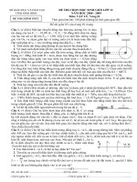
Figure 3 — Multi-hole mechanical mixing valve
15
Licensed copy: The University of Hong Kong, The University of Hong Kong, Version correct as of 18/04/2009 01:54, (c)
BSI
BS EN 817:2008
EN 817:2008 (E)
Figure 4 — Supply connections for mechanical mixing valve and remote outlets
16
Licensed copy: The University of Hong Kong, The University of Hong Kong, Version correct as of 18/04/2009 01:54, (c)
BSI
BS EN 817:2008
EN 817:2008 (E)
6.3
Outlet dimensions
Outlet dimensions shall be as specified in Table 4, 0, 0 and 0.
When nozzle outlets are used with flow rate regulators conforming to EN 246, the manufacturing tolerances chosen
for the connecting threads of the outlets shall be compatible with those of the connecting threads of the flow rate
regulators in order to ensure interchangeability.
Table 4 — Outlet dimensions (remote outlets, mechanical mixing valve)
Dimensions (mm)
Comments
Dimension from lowest point of the outlet
orifice including any flow rate regulator
or flow straightener to the mounting
surface. Regulations exist in some EU
Member States that set dimensions
greater than those indicated in this
European Standard.
Outlet orifice
E
25 min
- Lowest point
- All mixing valves and outlets
D1
90 min
Horizontal
valve
D3
115 min
Wall mounted mechanical mixing valve
Separate spout
A
G½B
A4
7,5 min
A5
mounted
mechanical
mixing
Remote outlet
Shower outlet
9,5 min
Dimension from the centre of outlet
orifice including any flow rate regulator
or flow straightener.
In accordance with EN ISO 228-1
Useful thread length
Free length of connection
Nozzle outlets to accept flow rate regulators shall be in accordance with EN 246.
NOTE Nozzle outlets not in accordance with EN 246 are covered by 6.5
17
Licensed copy: The University of Hong Kong, The University of Hong Kong, Version correct as of 18/04/2009 01:54, (c)
BSI
BS EN 817:2008
EN 817:2008 (E)
Figure 5 — Remote outlet
Figure 7 — Two hole mechanical mixing valve
18
Figure 6 — Single hole mechanical mixing valve
Licensed copy: The University of Hong Kong, The University of Hong Kong, Version correct as of 18/04/2009 01:54, (c)
BSI
BS EN 817:2008
EN 817:2008 (E)
6.4
Mounting dimensions
Mounting dimensions shall be as specified in Table 5, 0 and 0.
Table 5 — Mounting dimensions (outlets, single- and multi-hole mechanical mixing valve)
Dimensions (mm)
Comments
Shank diameter
H1
24 max
Two hole mechanical mixing valve size ½
Adjustable centres
H2
29 max
Side spray
Adjustable centres
H3
33,5 max
Single hole
Base or flange
J1
42 min
Side spray
J2
45 min
Bath, bath/shower, basin, bidet, sink
J3
50 max
Single and multi hole mechanical mixing valve
Diameter of clamping washer
V
32 max
Basin, bidet, sink
Flange projection to rear
V1
35 max
Bath – two hole mechanical mixing valve
L
Dimension of base or flange
Minimum range (mm) of supports,
Dimension which allows taps and outlets to be fitted on to
which allows the installation of the
supports of thickness between 1 mm and 18 mm.
mixing valves.
1
2
Key
1
basin – bidet – sink
2
remote spray attachment
Figure 8 — Single hole mechanical mixing valve
19
Licensed copy: The University of Hong Kong, The University of Hong Kong, Version correct as of 18/04/2009 01:54, (c)
BSI
BS EN 817:2008
EN 817:2008 (E)
Figure 9 — Two hole mechanical mixing valve
6.5
Special cases
Mechanical mixing valves intended for special applications, e.g. for installation on sanitary appliances not
conforming with European Standards, or where dimensional interchangeability is not a requirement can incorporate
dimensional deviations provided that:
all other requirements of this standard are satisfied;
secure fixing to the mounting surface is provided with all fixing holes covered;
thread connections to the supply pipes comply with EN ISO 228-1;
the air gap dimension E ≥ 25 mm or a backflow prevention device is provided in accordance with EN 1717.
the D 1 dimension is coordinated with the sanitary appliance.
The manufacturer's literature including the installation instructions supplied with the tapware shall indicate clearly
that the tapware is for special application.
6.6
Flexible hoses for shower outlets
Requirements for flexible hoses for shower outlets shall be as specified in EN 1113.
6.7
Shower outlets
Requirements for shower outlets shall be as specified in EN 1112.
20
Licensed copy: The University of Hong Kong, The University of Hong Kong, Version correct as of 18/04/2009 01:54, (c)
BSI
BS EN 817:2008
EN 817:2008 (E)
7
Sequence of testing
The samples shall be subjected to the test sequence shown in Table 6.
Table 6 — Test sequence
Sequence
Sample 1
1
dimensions
2
leaktightness
(Clause 8)
flow rate/sensitivity
(Clause 10)
3
endurance
(Clause 12)
mechanical strength
(Clause 11)
4
leaktightness
(Clause 8)
leaktightness
(Clause 8)
5
NOTE
8
Sample 2
pressure resistance
(Clause 9)
Acoustic testing will require three samples which can be different from the two mentioned above.
Leaktightness characteristics
8.1
General
This clause describes the test methods that shall be carried out to verify the leaktightness of the mechanical mixing
valve and specifies the corresponding requirements (see 0).
8.2
Test methods
8.2.1
Principle
The principle of the test consists of checking under cold water pressure the leaktightness of:
the obturator (see 8.3);
the complete mixing valve (see 8.4);
the bath/shower diverter (either manual or with automatic return) (see 8.5 and 8.6).
In the case of a diverter with automatic return being considered to provide backflow prevention, it shall comply with
the requirements of EN 14506.
8.2.2
Apparatus
A hydraulic test circuit capable of gradually supplying the required static and dynamic pressures and of maintaining
them throughout the duration of the test(s).
21
Licensed copy: The University of Hong Kong, The University of Hong Kong, Version correct as of 18/04/2009 01:54, (c)
BSI
BS EN 817:2008
EN 817:2008 (E)
8.3 Leaktightness of the obturator and of the mixing valve upstream of the obturator with the
obturator in the closed position
8.3.1
Procedure
a)
Connect the mixing valve to the test circuit;
b)
with the outlet orifice open, and the obturator closed;
c)
apply to the inlet of the mixing valve a water pressure of (1,6 ± 0,05) MPa [(16,0 ± 0,5) bar] and maintain it for
(60 ± 5) s.; during this period, move the temperature control device over its full operating range.
8.3.2
Requirements
Verification of leaktightness upstream of the obturator:
throughout the duration of the test there shall be no leakage or seepage through the walls;
Verification of leaktightness of the obturator:
8.4
throughout the duration of the test there shall be no leakage of the obturator, i.e. at the outlet.
Leaktightness of the mixing valve downstream of the obturator with the obturator open
8.4.1
General
Not applicable when the outlet cannot be closed.
8.4.2
Procedure
a) Connect the mixing valve to the test circuit;
b)
with the outlet orifice(s) artificially closed, and the obturator open;
c)
apply to the inlet of the mixing valve a water pressure of (0,4 ± 0,02) MPa [(4,0 ± 0,2) bar] and maintain it for
(60 ± 5) s; during this period, move the temperature control device over its full operating range;
d)
reduce gradually the pressure to (0,02 ± 0,002) MPa [(0,2 ± 0,02) bar] and maintain it for (60 ± 5) s.
8.4.3
Requirement
Throughout the duration of the test there shall be no leakage, or seepage through the walls.
8.5
Leaktightness of manually operated diverter
8.5.1
Procedure: flow to bath
a) Connect the mixing valve, in its normal position of use, to the test circuit;
b)
put the diverter in the flow-to-bath mode, the outlet to bath being artificially closed and the outlet to shower
open;
c)
apply a static water pressure of (0,4 ± 0,02) MPa [(4,0 ± 0,2) bar] and maintain it for (60 ± 5) s;
d)
gradually reduce the pressure to (0,02 ± 0,002) MPa [(0,2 ± 0,02) bar] and maintain it for (60 ± 5) s;
e)
check for leakage at the outlet to shower.
22
Licensed copy: The University of Hong Kong, The University of Hong Kong, Version correct as of 18/04/2009 01:54, (c)
BSI
BS EN 817:2008
EN 817:2008 (E)
8.5.2
Requirement: flow to bath
There shall be no leakage at the outlet to shower.
8.5.3
Procedure: flow to shower
a) Put the diverter in the flow-to-shower mode, the outlet to shower being artificially closed and the outlet to bath
open;
b)
apply a static water pressure of (0,4 ± 0,02) MPa [(4,0 ± 0,2) bar] and maintain it for (60 ± 5) s;
c)
gradually reduce the pressure to (0,02 ± 0,002) MPa [(0,2 ± 0,02) bar] and maintain it for (60 ± 5) s;
d)
check for leakage at the outlet to bath.
8.5.4
Requirement: flow to shower
There shall be no leakage at the outlet to bath.
8.6
Leaktightness and operation of diverter with automatic return
8.6.1
Procedure: flow to bath
a) Connect the mixing valve, in its normal position of use, to the test circuit;
b)
connect the hydraulic resistance corresponding to the flow rate class marking – see EN ISO 3822-4 to the
shower outlet (for example: for marking A, class A resistance will be used during testing);
c)
put the diverter in the flow-to-bath mode with the outlets to bath and shower open;
d)
apply a dynamic pressure of (0,4 ± 0,02) MPa [(4,0 ± 0,2) bar] and maintain it for (60 ± 5) s;
e)
check for leakage at the outlet to shower.
8.6.2
Requirement: flow to bath
There shall be no leakage at the outlet to shower.
8.6.3
Procedure: flow to shower
a) Put the diverter in the flow-to-shower mode with the outlets to bath and shower open;
b)
apply a dynamic pressure of (0,4 ± 0,02) MPa [(4,0 ± 0,2) bar] and maintain it for (60 ± 5) s;
c)
check for leakage at the outlet to bath;
d)
gradually reduce the pressure to (0,05 ± 0,002) MPa [(0,5 ± 0,02) bar] and maintain it for (60 ± 5) s;
e)
check the diverter position and check for leakage at the outlet to bath;
f)
close the mixing valve obturator; check the diverter position.
8.6.4
Requirement: flow to shower
There shall be no leakage at the outlet to bath whilst the diverter remains in the flow to shower position;
the diverter shall not return to the flow to bath position at any pressure ≥ (0,05 ± 0,002) MPa [(0,5 ± 0,02) bar];
23