Bsi bs en 00849 1997 (2002)
Bạn đang xem bản rút gọn của tài liệu. Xem và tải ngay bản đầy đủ của tài liệu tại đây (672.03 KB, 30 trang )
BS EN
849:1997
BRITISH STANDARD
Incorporating
Amendments Nos. 1
and 2
Transportable gas
cylinders —
Cylinder valves —
Specification and type
testing
--`,,,,``,`,,,,`,,,`,,`,`,``,,-`-`,,`,,`,`,,`---
The European Standard EN 849:1996, with the incorporation of
amendments A1:1999 and A2:2001, has the status of a British Standard
ICS 23.060.40
NO COPYING WITHOUT BSI PERMISSION EXCEPT AS PERMITTED BY COPYRIGHT LAW
Copyright British Standards Institution
Reproduced by IHS under license with BSI - Uncontrolled Copy
Document provided by IHS Licensee=Bureau Veritas/5959906001, 11/08/2004
06:09:50 MST Questions or comments about this message: please call the Document
Policy Group at 303-397-2295.
BS EN 849:1997
Committees responsible for this
British Standard
The preparation of this British Standard was entrusted to Technical
Committee PVE/3, Gas containers, upon which the following bodies were
represented:
Aluminium Extruders’ Association
Aluminium Federation
British Compressed Gases Association
British Fire Consortium
British Gas plc
British Iron and Steel Producers’ Association
British Soft Drinks Association Ltd.
Engineering Equipment and Materials Users’ Association
Fire Extinguishing Trades Association
Health and Safety Executive
Home Office
Institution of Chemical Engineers
LP Gas Association
Marine Safety Agency
Ministry of Defence
National Engineering Laboratory
National Physical Laboratory
Safety Assessment Federation Ltd.
Safety Equipment Association
Tubes Investments Limited
The following bodies were also represented in the drafting of the standard,
through sub-committees and panels:
British Association of Breathing Apparatus Service Engineers
This British Standard, having
been prepared under the
direction of the Engineering
Sector Board, was published
under the authority of the
Standards Board and comes
into effect on 15 March 1997
Department of Health
© BSI 14 January 2002
Amendments issued since publication
The following BSI references
relate to the work on this
standard:
Committee reference PVE/3
Draft for comment 92/812941 X
Amd. No. Date
Comments
10588
November
1999
Addition of new Annex C
13345
14 January
2002
Indicated by a sideline
ISBN 0 580 26783 0
Copyright British Standards Institution
Reproduced by IHS under license with BSI - Uncontrolled Copy
Document provided by IHS Licensee=Bureau Veritas/5959906001, 11/08/2004
06:09:50 MST Questions or comments about this message: please call the Document
Policy Group at 303-397-2295.
--`,,,,``,`,,,,`,,,`,,`,`,``,,-`-`,,`,,`,`,,`---
Tube Investments Chesterfield Tube Co. Ltd.
BS EN 849:1997
Contents
Committees responsible
National foreword
Page
Inside front cover
ii
Foreword
Text of EN 849
2
3
--`,,,,``,`,,,,`,,,`,,`,`,``,,-`-`,,`,,`,`,,`---
© BSI 14 January 2002
Copyright British Standards Institution
Reproduced by IHS under license with BSI - Uncontrolled Copy
Document provided by IHS Licensee=Bureau Veritas/5959906001, 11/08/2004
06:09:50 MST Questions or comments about this message: please call the Document
Policy Group at 303-397-2295.
i
BS EN 849:1997
National foreword
This British Standard has been prepared by Technical Committee PVE/3 and is
the English language version of EN 849:1996 Transportable gas cylinders —
Cylinder valves — Specification and type testing, including amendments A1:1999
and A2:2001, published by the European Committee for Standardization (CEN).
EN 849 was produced as a result of international discussions in which the United
Kingdom took an active part.
This British Standard partially supersedes BS 341-1:1962, BS 341-1:1991 and
BS 341-2:1963 which will be amended to elimate conflicting requirements.
--`,,,,``,`,,,,`,,,`,,`,`,``,,-`-`,,`,,`,`,,`---
Cross-references
The British Standards which implement international or European publications
referred to in this document may be found in the BSI Standards Catalogue under
the section entitled “International Standards Correspondence Index”, or by using
the “Find” facility of the BSI Standards Electronic Catalogue.
The Technical Committee has reviewed the provisions of ISO 5145:1990 to which
normative reference is made in the text, and has decided that they are acceptable
for use in conjunction with this standard.
A British Standard does not purport to include all the necessary provisions of a
contract. Users of British Standards are responsible for their correct application.
Compliance with a British Standard does not of itself confer immunity
from legal obligations.
Summary of pages
This document comprises a front cover, an inside front cover, pages i and ii,
the EN title page, pages 2 to 24, an inside back cover and a back cover.
The BSI copyright notice displayed in this document indicates when the
document was last issued.
Sidelining in this document indicates the most recent changes by amendment
ii
Copyright British Standards Institution
Reproduced by IHS under license with BSI - Uncontrolled Copy
© BSI
14 January
Document provided by IHS Licensee=Bureau Veritas/5959906001,
11/08/2004
06:09:50 MST Questions or comments about this message: please call the Document
Policy Group at 303-397-2295.
2002
--`,,,,``,`,,,,`,,,`,,`,`,``,,-`-`,,`,,`,`,,`---
EUROPEAN STANDARD
EN 849
NORME EUROPÉENNE
July 1996
+ A1
EUROPÄISCHE NORM
April 1999
+ A2
June 2001
ICS 23.060.00
Descriptors: Gas cylinders, compressed gases, liquified gases, dissolved gases, gas valves, design, performance evaluation,
conformity tests, marking
English version
Transportable gas cylinders —
Cylinder valves —
Specification and type testing
(includes amendments A1:1999 and A2:2001)
Bouteilles à gaz transportables — Robinets de
bouteilles — Spécifications et essais de type
(inclut les amendements A1:1999 et A2:2001)
Ortsbewegliche Gasflaschen —
Flaschen-Ventile — Spezifikation und
Typprüfung
(enhält Änderungen A1:1999 und A2:2001)
www.bzfxw.com
This European Standard was approved by CEN on 1996-01-22; amendment A1
was approved by CEN on 1999-01-08. Amendment A2:2001 was approved by
CEN on 2001-05-10. CEN members are bound to comply with the
CEN/CENELEC Internal Regulations which stipulate the conditions for giving
this European Standard the status of a national standard without any
alteration.
Up-to-date lists and bibliographical references concerning such national
standards may be obtained on application to the Central Secretariat or to any
CEN member.
This European Standard exists in three official versions (English, French,
German). A version in any other language made by translation under the
responsibility of a CEN member into its own language and notified to the
Central Secretariat has the same status as the official versions.
CEN members are the national standards bodies of Austria, Belgium, Denmark,
Finland, France, Germany, Greece, Iceland, Ireland, Italy, Luxembourg,
Netherlands, Norway, Portugal, Spain, Sweden, Switzerland and United
Kingdom.
CEN
European Committee for Standardization
Comité Européen de Normalisation
Europäisches Komitee für Normung
Central Secretariat: rue de Stassart 36, B-1050 Brussels
© 1996 Copyright reserved to CEN members.
Copyright British Standards Institution
Reproduced by IHS under license with BSI - Uncontrolled Copy
Ref. No. EN 849:1996 + A1:1999 + A2:2001 E
Document provided by IHS Licensee=Bureau Veritas/5959906001, 11/08/2004
06:09:50 MST Questions or comments about this message: please call the Document
Policy Group at 303-397-2295.
EN 849:1996
--`,,,,``,`,,,,`,,,`,,`,`,``,,-`-`,,`,,`,`,,`---
Foreword
This European Standard has been prepared by
Technical Committee CEN/TC 23, Transportable
gas cylinders, the Secretariat of which is held by
BSI.
This European Standard shall be given the status of
a national standard, either by publication of an
identical text or by endorsement, at the latest by
January 1997, and conflicting national standards
shall be withdrawn at the latest by January 1997.
This European Standard has been submitted for
reference into the RID and/or the technical annexes
of the ADR. Therefore in this context the standards
listed in the normative references and covering
basic requirements of the RID/ADR not addressed
within the present standard are normative only
when the standards themselves are referred to in
the RID and/or the technical annexes of the ADR.
According to the CEN/CENELEC Internal
Regulations, the national standards organizations
of the following countries are bound to implement
this European Standard: Austria, Belgium,
Denmark, Finland, France, Germany, Greece,
Iceland, Ireland, Italy, Luxembourg, Netherlands,
Norway, Portugal, Spain, Sweden, Switzerland and
the United Kingdom.
Foreword to amendment A1
This amendment EN 849:1996/A1:1999 to
EN 849:1996 has been prepared by Technical
Committee CEN/TC 23, Transportable gas
cylinders, the Secretariat of which is held by BSI.
This amendment to the European Standard
EN 849:1996 shall be given the status of a national
standard, either by publication of an identical text
or by endorsement, at the latest by October 1999,
and conflicting national standards shall be
withdrawn at the latest by October 1999.
This European Standard has been submitted for
reference into the RID and/or the technical annexes
of the ADR. Therefore in this context the standards
listed in the normative references and covering
basic requirements of the RID/ADR not addressed
within the present standard are normative only
when the standards themselves are referred to in
the RID and/or the technical annexes of the ADR.
Foreword to amendment A2
This amendment EN 849:1996/A2:2001 to
EN 849:1996 has been prepared by Technical
Committee CEN/TC 23, Transportable gas
cylinders, the Secretariat of which is held by BSI.
This amendment to the European Standard
EN 849:1996 shall be given the status of a national
standard, either by publication of an identical text
or by endorsement, at the latest by December 2001,
and conflicting national standards shall be
withdrawn at the latest by December 2001.
This amendment to EN 849 has been prepared to
align certain requirements with RID/ADR.
This European Standard has been submitted for
reference into the RID and/or the technical annexes
of the ADR. Therefore in this context the standards
listed in the normative references and covering
basic requirements of the RID/ADR not addressed
within the present standard are normative only
when the standards themselves are referred to in
the RID and/or the technical annexes of the ADR.
www.bzfxw.com
According to the CEN/CENELEC Internal
Regulations, the national standards organizations
of the following countries are bound to implement
this European Standard: Austria, Belgium, Czech
Republic, Denmark, Finland, France, Germany,
Greece, Iceland, Ireland, Italy, Luxembourg,
Netherlands, Norway, Portugal, Spain, Sweden,
Switzerland and the United Kingdom.
This amendment to EN 849 has been prepared to
clarify certain important parameters and aspects of
testing cyclinder valves in accordance with
EN 849, 5.4.4.
According to the CEN/CENELEC Internal
Regulations, the national standards organizations
of the following countries are bound to implement
this European Standard: Austria, Belgium, Czech
Republic, Denmark, Finland, France, Germany,
Greece, Iceland, Ireland, Italy, Luxembourg,
Netherlands, Norway, Portugal, Spain, Sweden,
Switzerland and the United Kingdom.
2
Copyright British Standards Institution
Reproduced by IHS under license with BSI - Uncontrolled Copy
© BSI11/08/2004
14 January
Document provided by IHS Licensee=Bureau Veritas/5959906001,
06:09:50 MST Questions or comments about this message: please call the Document
Policy Group at 303-397-2295.
2002
EN 849:1996
Contents
Page
Foreword
2
Introduction
3
1
Scope
4
2
Normative references
4
3
Definitions and symbols
4
4
Valve requirements
5
5
Prototype valve test
9
6
Marking
18
7
Test report
18
Annex A (normative) Valve impact test
19
Annex B (informative) Example of test
sequence
21
Annex C (normative) Endurance test
22
Figure 1 — External tightness
6
Figure 2 — Internal tightness
7
Figure 3 — Maximum dimensions for gas cylinder
valves, protected by a cap
8
Figure 4 — Example of an ignition test
installation
15
Figure 5 — Pressure cycle specification
16
Figure 6 — Example of acetylene flashback test
apparatus
17
Figure A.1 — Impact test
20
Figure C.1 — Typical arrangement of computer
controlled equipment
23
Figure C.2 — Diagram showing a typical cycle
for endurance test
24
Table 1 — Sequence of tests (tightness,
endurance and fire resistance) for type
approval (no variants)
11
Table 2 — Test pressures for tightness tests
12
Table 3 — Test sequence
14
Deleted
Table B.1 — Sequence of tests for type
approval (basic design plus two type variants) 21
www.bzfxw.com
--`,,,,``,`,,,,`,,,`,,`,`,``,,-`-`,,`,,`,`,,`---
© BSI 14 January 2002
Copyright British Standards Institution
Reproduced by IHS under license with BSI - Uncontrolled Copy
Document provided by IHS Licensee=Bureau Veritas/5959906001, 11/08/2004
06:09:50 MST Questions or comments about this message: please call the Document
Policy Group at 303-397-2295.
3
EN 849:1996
Introduction
The increased use of compressed gases has led to a corresponding increase in the number of gas cylinders
that are in circulation throughout the world.
Each gas cylinder is fitted with a valve, to contain and control the discharge of its contents.
Such valves normally conform to standards of performance and safety.
1 Scope
This European Standard specifies requirements for gas cylinder valves and the method of testing such
valves, for type approval.
This standard is applicable to valves to be fitted to gas cylinders, up to 150 l water capacity, intended to
convey compressed, liquefied or dissolved gases.
This standard is only applicable to valves operated by a hand wheel or a key.
This standard is not applicable to valves for breathing equipment, fire extinguishers or cryogenic
equipment.
This standard is primarily for industrial gases other than LPG but may also be applied for LPG. However
for dedicated LPG cylinders, see prEN 13153:1998, Specification and testing for Liquefied Petroleum Gases
(LPG) — Cylinder valves — Manually operated, prepared by CEN/TC 286, Liquefied petroleum gas
equipment and accessories.
2 Normative references
This European Standard incorporates by dated or undated reference, provisions from other publications.
These normative references are cited at the appropriate place in the text and the publications are listed
hereafter. For dated references, subsequent amendments to or revisions of any of these publications apply
to this European Standard only when incorporated in it by amendment or revision. For undated references
the latest edition of the publication referred to applies.
EN 720-2, Transportable gas cylinders — Gases and gas mixtures — Part 2: Determination of flammability
and oxidizing ability of gases and gas mixtures.
EN 962, Transportable gas cylinders — Valve protection caps and valve guards for industrial and medical
gas cylinders — Design, construction and tests.
ISO 188, Rubber, vulcanized — Accelerated ageing or heat-resistance tests.
ISO 1817, Rubber, vulcanized — Determination of the effect of liquids.
ISO 5145:1990, Cylinder valve outlets for gases and gas mixtures — Selection and dimensioning.
3 Definitions and symbols
For the purposes of this standard, the following definitions and symbols apply.
3.1
working pressure (pw)
settled pressure, at a uniform temperature of 15 ºC, for a full gas cylinder
3.2
operating pressure (po)
varying pressure which is developed in a cylinder during service
3.3
valve test pressure (pvt)
for compressed gases:
pvt = 1,2 × pw
for liquefied gases and dissolved gases under pressure (for example, acetylene): pvt shall be at least equal
to the minimum test pressure of the cylinder quoted in the relevant transport regulation for that gas or gas
group
4
Copyright British Standards Institution
Reproduced by IHS under license with BSI - Uncontrolled Copy
© BSI11/08/2004
14 January
Document provided by IHS Licensee=Bureau Veritas/5959906001,
06:09:50 MST Questions or comments about this message: please call the Document
Policy Group at 303-397-2295.
2002
--`,,,,``,`,,,,`,,,`,,`,`,``,,-`-`,,`,,`,`,,`---
www.bzfxw.com
EN 629-1, Transportable gas cylinders — 25E taper thread for connection of valves to gas cylinders —
Part 1: Specification.
EN 849:1996
3.4
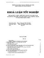
external tightness
tightness to atmosphere (leakage in and/or leakage out) when the valve is open (see Figure 1)
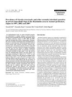
3.5
internal tightness
tightness across the valve seat (leakage in and/or leakage out) when the valve is closed (see Figure 2)
3.6
minimum closing torque (Tc)
minimum closing torque necessary to obtain the internal tightness
3.7
resistance torque
maximum closing torque the valve can withstand without damage
3.8
valve operating mechanism
manually rotated device, which closes and opens the valve orifice
4 Valve requirements
4.1 General
Valves shall operate satisfactorily over the full range of service temperatures, normally from – 20 ºC
to +65 ºC. The range may be extended for short periods (e.g. during filling). Where higher or lower service
temperatures are required for longer periods, the purchaser shall specify accordingly.
www.bzfxw.com
Valves shall be capable of withstanding the mechanical stresses or chemical attack they may experience
during normal service.
Valves shall be cleaned to meet the requirements of the intended service.
4.2 Description and dimensions
A cylinder valve comprises:
— a body;
— a valve operating mechanism and internal sealing device;
— an external sealing mechanism;
— a connection(s) for usage (fill and discharge);
— a connection system, between the valve and gas cylinder;
and occasionally:
— a safety device, against overpressurization;
— a siphon tube;
— a screwed plug or cap, on the outlet connection, to ensure leak tightness or protection;
— an excess flow limiting device.
The bore of the valve shall be adequate to meet the requirements of flow rate, without unacceptably
reducing the strength of the stem connection. The bore diameter, typically 3,5 mm for valves with a 25E
stem thread (see EN 629-1) and 2 mm for valves with a 17E stem thread, shall be agreed between customer
and supplier.
Where a valve is to be protected by a cap in accordance with EN 962 the valve should comply with the
dimensions given in Figure 3.
--`,,,,``,`,,,,`,,,`,,`,`,``,,-`-`,,`,,`,`,,`---
© BSI 14 January 2002
Copyright British Standards Institution
Reproduced by IHS under license with BSI - Uncontrolled Copy
Document provided by IHS Licensee=Bureau Veritas/5959906001, 11/08/2004
06:09:50 MST Questions or comments about this message: please call the Document
Policy Group at 303-397-2295.
5
EN 849:1996
4.3 Materials
Metallic and non-metallic materials in contact with the gas shall be chemically and/or physically
compatible with the gas, under all intended operating conditions.
Compatibility of materials with oxygen and other oxidizing gases, ignition resistance of materials and
lubricants, shall be established by an appropriate test procedure.
Valves for acetylene may be manufactured from copper based alloys if the copper content does not exceed
70 % (by weight). The manufacturer shall not use any procedure resulting in copper enrichment of the
surface. Silver content of alloys shall be limited for acetylene valves. The acceptable limit varies between
43 % (by weight) and 50 % (by weight), depending on the composition of the alloy.
Non-metallic sealing material for use with air, oxygen and oxygen enriched gases, shall be capable of
withstanding an ageing sensitivity test in accordance with ISO 188.
Non-metallic sealing material in valves shall be capable of withstanding corrosive media tests in
accordance with ISO 1817.
www.bzfxw.com
--`,,,,``,`,,,,`,,,`,,`,`,``,,-`-`,,`,,`,`,,`---
6
Copyright British Standards Institution
Reproduced by IHS under license with BSI - Uncontrolled Copy
Figure 1 — External tightness
© BSI11/08/2004
14 January
Document provided by IHS Licensee=Bureau Veritas/5959906001,
06:09:50 MST Questions or comments about this message: please call the Document
Policy Group at 303-397-2295.
2002
Figure 2 — Internal tightness
--`,,,,``,`,,,,`,,,`,,`,`,``,,-`-`,,`,,`,`,,`---
EN 849:1996
4.4 Design and construction
4.4.1 Valve body
The valve body shall be manufactured by a process that will ensure the reproducibility of the mechanical
characteristics necessary to meet the requirements specified in this standard, particularly that specified
in 5.4.2. The anisotropy of the material shall be considered.
4.4.2 Valve connections
Valves are normally connected to the cylinder by means of a taper or parallel male thread and to the filling
and utilization appliances by means of a separate outlet connection, complying with an accepted standard.
4.4.3 Valve operating mechanism
The valve operating mechanism shall be manufactured from materials capable of withstanding mechanical
stress including possible dynamic loads (for example, pressure shocks or cyclic changes) and the extremes
of service temperature, to which it may be subjected.
The materials of the valve operating mechanism shall withstand fire engulfment in accordance with 5.4.10.
The valve operating mechanism shall satisfy the following conditions:
— it shall not be dependent on the pressure in the cylinder;
— it shall, under normal conditions operate without difficulty throughout its service life;
— it shall be designed in such a way that it cannot be unscrewed from the valve body with a torque less
than 40 N·m;
— it shall be designed in such a way that the setting of the operating position of the valve, cannot be
inadvertently altered;
— it shall close the valve by clockwise rotation;
— it shall be designed to ensure that lubricants that are not oxygen compatible, do not come into contact
with highly oxidizing gases as defined in EN 720-2;
— for acetylene valves, it shall be designed to meet the requirements of 5.4.9.
© BSI 14 January 2002
Copyright British Standards Institution
Reproduced by IHS under license with BSI - Uncontrolled Copy
Document provided by IHS Licensee=Bureau Veritas/5959906001, 11/08/2004
06:09:50 MST Questions or comments about this message: please call the Document
Policy Group at 303-397-2295.
7
EN 849:1996
For valves for oxygen or highly oxidizing gases, the opening of the valve orifice shall be progressive.
Complete opening shall require more than one rotation of the operating mechanism. For valves, in which
it is technically difficult to limit opening in this way (for example diaphragm valves) other means shall be
provided to delay full gas flow.
--`,,,,``,`,,,,`,,,`,,`,`,``,,-`-`,,`,,`,`,,`---
Figure 3 — Maximum dimensions for gas cylinder valves, protected by a cap
4.4.4 Tightness
Methods of achieving external tightness include:
— gland packing;
— one or several O-rings;
— diaphragm;
— bellows;
— any other appropriate device.
External and internal tightness, shall be achieved over the full range of service pressures and
temperatures.
The external tightness shall be maintained for all positions of the valve spindle, from the opening, to the
complete closing, and during operation.
All sealing devices shall withstand 2 000 opening and closing cycles, at pvt, without replacement of the
sealing device. Adjustment is permitted.
The minimum gauge pressure, during the tightness test, shall be 0,1 bar. Where the valve is not intended
for use with flammable or toxic gases this pressure may be increased to 0,5 bar.
8
Copyright British Standards Institution
Reproduced by IHS under license with BSI - Uncontrolled Copy
© BSI11/08/2004
14 January
Document provided by IHS Licensee=Bureau Veritas/5959906001,
06:09:50 MST Questions or comments about this message: please call the Document
Policy Group at 303-397-2295.
2002
EN 849:1996
At the customers request the tightness test may be carried out under vacuum.
When incorporating diaphragms or bellows, additional gland packings or O-rings, may be used to ensure
safety, in case of deterioration of the diaphragms or the bellows. This particularly applies for toxic gases.
The tightness test is normally carried out with air or nitrogen. Valves designated for use with gases lighter
than air, or very searching gases (for example carbon dioxide) may be subjected to a test using helium.
For the definition of a flammable gas see EN 720-2, and for the definition of a toxic gas see annex A of
ISO 5145:1990.
4.4.5 Leakage rate
The internal or external leakage rate shall not exceed 6 cm3/h at 20 ºC and 1 013 mbar.
The specified rate may be amended by agreement and subject to special applications, for example, for
valves for highly toxic or high purity gas service, a lower leakage rate may be specified.
4.4.6 Operating torque
--`,,,,``,`,,,,`,,,`,,`,`,``,,-`-`,,`,,`,`,,`---
For handwheel operated valves, with a handwheel diameter of 65 mm, the closing torque to obtain internal
tightness, shall be 7 N·m or less. For certain valves (for example key operated or diaphragm valves) this
torque may be higher. The size of the handwheel, or equivalent operating device, shall be appropriate for
the required closing torque (see 5.4.3.2 and 5.4.6).
The torque necessary for the complete closing and opening of the valve, shall not increase significantly
during the valve’s service life (see 5.4.4).
5 Prototype valve test
5.1 General
Before valves are introduced into service, they shall be submitted for type approval (see 5.2 and 5.3). A type
approval is valid for a given family of valves, having the same basic design.
Variations to connections do not require further type testing.
Changes to the internal components for reasons of gas/material compatibility (for example “O” ring,
packing, diaphragm, spindle, lubricant) constitute a type variant within the given family.
Type variants require repetition of the relevant parts of the type test.
Changes of the basic design dimensions of components or changes of valve body material, constitute a new
family and require the full type test.
5.2 Documents
The manufacturer shall make available, to the test authority, the following documents:
— a set of drawings consisting of the general arrangement, parts list, material specifications and detail
drawings. Any type variant, within the given family, shall be clearly identified;
— description of valve and method of operation;
— information on the field of application of the valve (gases and gas mixtures, pressures, use with or
without valve protection device, etc). It shall be clearly indicated which gases and gas mixtures can be
used with each type variant;
— certificates of material compatibility as required.
© BSI 14 January 2002
Copyright British Standards Institution
Reproduced by IHS under license with BSI - Uncontrolled Copy
Document provided by IHS Licensee=Bureau Veritas/5959906001, 11/08/2004
06:09:50 MST Questions or comments about this message: please call the Document
Policy Group at 303-397-2295.
9
EN 849:1996
5.3 Test valves
A minimum of nine sample valves are required (more samples may be necessary, depending on the number
of type variants to be tested):
--`,,,,``,`,,,,`,,,`,,`,`,``,,-`-`,,`,,`,`,,`---
— one sample (No. 1) for the hydraulic pressure test;
— samples for tightness tests and endurance test as follows:
1) when no type variants are specified, five samples of the basic specification shall be tested.
(Nos. 2 to 6);
2) when one type variant a) is specified, three samples (Nos. 2, 3, 4) of the basic specification and two
samples (Nos. 5a and 6a) of the type variant shall be tested;
3) when two or more type variants (a, b, etc.) are specified, two samples (Nos. 2 and 3) of the basic
specification, and two samples of each type variant (Nos. 4a and 5a, 4b and 5b, etc.) shall be tested.
— one sample (No. 2) is also used for fire exposure test;
— one sample (No. 7) for any additional test which may be required;
— two samples (Nos. 8 and 9) for determination of operating torques.
In addition:
a) for oxygen or highly oxidizing gas service, three sample valves (10n, 11n and 12n) are required for the
oxygen pressure surge test;
b) for acetylene service, three sample valves (10m, 11m, and 12m) are required for the internal tightness
test after flashback.
5.4 Test procedure
5.4.1 Table of tests
Tests shall be carried out, in accordance with the schedule given in Table 1.
See Annex B, for an example of test sequence for a basic design with type variants.
10
Copyright British Standards Institution
Reproduced by IHS under license with BSI - Uncontrolled Copy
© BSI11/08/2004
14 January
Document provided by IHS Licensee=Bureau Veritas/5959906001,
06:09:50 MST Questions or comments about this message: please call the Document
Policy Group at 303-397-2295.
2002
EN 849:1996
--`,,,,``,`,,,,`,,,`,,`,`,``,,-`-`,,`,,`,`,,`---
Table 1 — Sequence of tests (tightness, endurance and fire resistance) for type approval
(no variants)
Test
Test and sub-clause
sequence
No.
Condition of test valve
Test
temperature
ºC
Valve sample
number
No. of
test/valve
1
Hydraulic 5.4.2
As received
20 ± 5
1
1
2
Internal/external As received
tightness 5.4.3
20 ± 5
2c
6a
3
Internal/external From test sequence 2, 20 ± 5
tightness 5.4.3
aged at 65 ºC for 5 days
4
Endurance 5.4.4
From test sequence 3
5
1
or 8
30a or 40
2c to 6
6a or 8
30a or 40
20 ± 5
2c to 6
1
5
Internal/external From test sequence 4
tightness 5.4.3
20 ± 5
2c to 6
6a or 8
30a or 40
6
Internal/external From test sequence 5
tightness 5.4.3
65 ± 2,5
2c to 6
6a or 8
30a or 40
7
Internal/external From test sequence 6
tightness 5.4.3
–0 ± 2,5b
2c to 6
6a or 8
30a or 40
8
Visual
From test sequence 7
examination 5.4.5
20 ± 5
2c to 6
1
5
9
Excessive torque As received
5.4.6
20 ± 5
8 and 9
1
2
10
Fire exposure
5.4.10
800 to 1 000 2
1
1
a
b
c
From test sequence 8
to 6
Total No. of
tests
The total number of tests will be 30 without vacuum test and 40 if vacuum test is required.
For some parts of Europe and for certain applications, tests at a lower temperature (e.g. –30 °C) shall be considered.
For additional type variants, valve sample numbers and tests will change in accordance with 5.3.
5.4.2 Hydraulic pressure test
For safety reasons this test shall be carried out prior to all other tests.
The hydraulic pressure test shall be carried out under the following conditions:
— valve seat in open position;
— valve outlet connection sealed;
— safety relief devices (where fitted) removed and the opening sealed;
— test medium, water or other suitable fluid;
— hydraulic test pressure, 1,5 × test pressure of the cylinder, except for valves for acetylene, where the
test pressure of the valve shall be 450 bar;
— test temperature, ambient temperature (20 ± 5) ºC;
— pressure holding time, 2 minutes minimum.
The pressure shall be raised continuously and gradually. The prototype valve shall withstand the test,
without permanent deformation or rupture.
© BSI 14 January 2002
Copyright British Standards Institution
Reproduced by IHS under license with BSI - Uncontrolled Copy
Document provided by IHS Licensee=Bureau Veritas/5959906001, 11/08/2004
06:09:50 MST Questions or comments about this message: please call the Document
Policy Group at 303-397-2295.
11
EN 849:1996
5.4.3 Tightness tests
5.4.3.1 General
Each internal and external tightness test sequence shall comprise a test at four pressure settings as shown
in Table 2.
The test pressure shall be held for not less than 1 minute.
Table 2 — Test pressures for tightness tests
Test pressure sequence
Test pressure for tightness tests
1
vacuum (e.g. 5 × 10⁻³ bar) if required
2
0,1 bar for toxic and flammable gases, 0,5 bar for all other gases
3
10 bar for all gases
4
The higher of either pvt for permanent gases or the test pressure of the gas
cylinder for liquefied and dissolved gases, but never less than 20 bar.
5.4.3.2 Internal tightness
The internal tightness shall be determined in relation to the closing torque in accordance with the following
procedure, on each of the five or more sample valves (see 5.3):
a) blank off the valve outlet connection;
b) remove the safety relief device (where fitted) and seal the opening;
c) open the valve;
d) apply the specified pressure to the valve inlet;
e) close the valve to the desired torque. It is especially important that diaphragm valves are pressurized
when the valve is being closed;
f) open the valve outlet connection;
g) wait at least 1 min before measuring the seat leakage rate;
h) If the leakage rate is unacceptable (see 4.4.5) repeat the test sequence at a higher valve closing torque.
This test sequence shall be repeated for each test pressure given in Table 2.
5.4.3.3 External tightness
The external tightness shall be determined, using the following procedure, on each of the five or more
sample valves (see 5.3):
a) blank off one opening (inlet or outlet) of the valve;
b) remove the safety relief device (where fitted) and seal the opening;
c) fully open the valve;
d) apply the specified pressure through the other opening;
e) measure the leakage rate;
f) partially close the valve;
g) measure the leakage rate.
If required, action f) and action g) may be repeated for different partial closings.
For test sequence 7 of Table 1, carried out at (–20 ± 2,5) °C, the external leakage rate shall also be measured
while the handwheel is being rotated.
12
--`,,,,``,`,,,,`,,,`,,`,`,``,,-`-`,,`,,`,`,,`---
Copyright British Standards Institution
Reproduced by IHS under license with BSI - Uncontrolled Copy
© BSI11/08/2004
14 January
Document provided by IHS Licensee=Bureau Veritas/5959906001,
06:09:50 MST Questions or comments about this message: please call the Document
Policy Group at 303-397-2295.
2002
EN 849:1996
--`,,,,``,`,,,,`,,,`,,`,`,``,,-`-`,,`,,`,`,,`---
5.4.4 Endurance test
An endurance test of 2 000 cycles, consisting of fully opening and closing of the valve, shall be carried out
at pvt.
After each closure the pressure downstream of the seat shall be released to atmosphere. There shall be, at
least, a 6 s pause at each fully open and fully closed position.
Care should be taken to ensure that, during the test, friction does not cause the valve temperature to exceed
significantly that specified in Table 1.
For handwheel valves, the closing torque used during the test shall be 7 N·m. No significant torque shall
be applied in the fully open position.
For key operated or diaphragm valves which require a minimum closing torque (Tc) greater than 7 N·m,
the torque used during the test shall be equal to 1,5 × Tc.
For small valves, with a minimum closing torque of less than 7 N·m, the torque used, during the test, shall
be twice the minimum closing torque, subject to a maximum of 7 N·m.
For all subsequent tests, the torque used during the endurance test shall not be exceeded.
For further details see Annex C.
5.4.5 Visual examination
When the endurance test and the subsequent tightness tests have been completed, sealing elements such
as diaphragms, bellows, O-rings, shall be subject to a visual check for unacceptable wear and/or damage.
5.4.6 Determination of resistance to excessive torque
The intent of these tests is to check that the valve operating mechanism has adequate strength, and fails
safely if subjected to excessive torque.
These tests shall be carried out on the sample valves 8 and 9, at atmospheric pressure.
The closing torque on sample valve 8 shall gradually be increased to a given torque T (see below), at this
torque the valve shall be able to work without noticeable difficulties and shall not show any significant
damage. The torque shall then be increased until failure occurs of any part of the operating device. The
value of the torque, at failure, shall be not less than 1,25 × T.
This test shall then be repeated, on sample valve 9, but with an opening torque instead of a closing torque.
After this test, the valve operating mechanism may be severely damaged and not working. No pressure
retaining components shall have failed. Disassembly of the mechanism is not permitted during this test.
The value of T for standard industrial gas cylinder valves, fitted with a 65 mm diameter handwheel,
is 20 N·m.
This value of T will vary with the design of valve and operating mechanism, it may, for small valves be
lower and for key operated valves be greater.
The operating mechanism shall not be capable of withstanding a torque in excess of that required to
disassemble the operating mechanism from the valve body (see 4.4.3).
5.4.7 Mechanical impact test
If it is not intended for the valve to be protected during transport by a cap or another form of guarding, an
impact test shall be carried out on valve sample 7, as described in Annex A.
5.4.8 Oxygen pressure surge test
This test shall be carried out for valves used in all applications where the gas or gas mixture is highly
oxidizing (see EN 720-2). For all types of valve the pressure surge test shall be carried out with pure
oxygen.
The purpose of the test is to check whether the valve withstands an oxygen pressure surge safely.
Three sample valves, samples 10 to 12, in the “as received” condition, or lubricated, if a lubricant is used
for such a valve, shall be tested.
Before the test, the ignition test installation shall be checked for the required pressure rise (for examples
of test installation and pressure cycle specification, see Figure 4 and Figure 5). For this purpose the test
valve, at the end of the 1 m length of copper tube, is replaced by a reliable pressure gauge.
© BSI 14 January 2002
Copyright British Standards Institution
Reproduced by IHS under license with BSI - Uncontrolled Copy
Document provided by IHS Licensee=Bureau Veritas/5959906001, 11/08/2004
06:09:50 MST Questions or comments about this message: please call the Document
Policy Group at 303-397-2295.
13
EN 849:1996
The maximum pressure at the dead end of the copper tube (measured by pressure gauge and recorded on
an oscilloscope) shall be achieved within (20 ± 5) ms (time necessary to reach pvt starting from atmospheric
pressure).
Stabilization time at pvt is not fixed but shall be greater than or equal to 3 s. Before the next pressure surge
the system (sample valve and copper tube) shall be depressurized down to atmospheric pressure.
Stabilization time at atmospheric pressure is not fixed but shall be greater than, or equal to 3 s.
The total time of the pressure cycle shall be 30 s, as illustrated in Figure 5, total time is the time between
the beginning of two consecutive pressure surges.
For calibration purposes, heated oxygen at (60 ± 3) ºC shall be used.
The quality of oxygen shall be:
— minimum purity 99,5 %, by volume;
— hydrocarbon content K 10 × 10–6 p.p.m.
Each test shall be carried out as follows:
— supply oxygen at a temperature of (60 ± 3) ºC, directly into the connection of the valve to be tested, by
means of a copper tube having an internal diameter of 5 mm and a length of 1 m. The specified material
and dimensions of the tube, are essential in order to ensure that a well defined energy input into the
valve to be tested is achieved;
— two test sequences shall be carried out in accordance with Table 3;
— oxygen is heated up to (60 ± 3) ºC, in the oxygen pre-heater. Inlet of oxygen, to the test sample valve,
is controlled by a quick opening valve (see Figure 4). The test consists of subjecting the sample valve to 50
pressure cycles from atmospheric pressure to the valve test pressure (pvt) (see Figure 5).
After the tests, the sample valve shall be dismantled and carefully checked, including close examination of
non-metallic components. It shall not show any traces of ignition.
Table 3 — Test sequence
Test sequence
Valve operating system
Valve stem
Closed
Open
2
Open
Sealed with a screwed metallic plug
--`,,,,``,`,,,,`,,,`,,`,`,``,,-`-`,,`,,`,`,,`---
1
14
Copyright British Standards Institution
Reproduced by IHS under license with BSI - Uncontrolled Copy
© BSI11/08/2004
14 January
Document provided by IHS Licensee=Bureau Veritas/5959906001,
06:09:50 MST Questions or comments about this message: please call the Document
Policy Group at 303-397-2295.
2002
EN 849:1996
--`,,,,``,`,,,,`,,,`,,`,`,``,,-`-`,,`,,`,`,,`---
Figure 4 — Example of an ignition test installation
© BSI 14 January 2002
Copyright British Standards Institution
Reproduced by IHS under license with BSI - Uncontrolled Copy
Document provided by IHS Licensee=Bureau Veritas/5959906001, 11/08/2004
06:09:50 MST Questions or comments about this message: please call the Document
Policy Group at 303-397-2295.
15
EN 849:1996
Figure 5 — Pressure cycle specification
5.4.9 Acetylene flashback test
This test is for valves intended for acetylene service.
The purpose of the test is to establish whether the sample valve is able to withstand an acetylene flashback.
After the flashback test, it shall be possible to close the valve.
Where the sample valve is fitted with an integral pressure relief device, this device shall be closed for the
test.
The acetylene cylinder used for the test, shall have a free volume at the top of the cylinder of
approximately 150 cm3.
The sample valve shall be screwed into an acetylene cylinder of 5 l water capacity (prepared with porous
mass and solvent). No neck filter shall be fitted to the cylinder or the valve.
The cylinder shall be filled with at least half of its maximum permissible quantity of acetylene. An igniter
tube of volume 30 cm3 is connected to the outlet boss (see Figure 6). This igniter tube is closed at one end
by a bursting disc having a maximum burst pressure of 40 bar. The decomposition of the acetylene,
propagates into the cylinder causing, due to a pressure rise, the rupture of the bursting disc, hot
decomposition gases flow out of the valve.
After 30 s the sample valve shall be closed, from a safe distance (i.e. by remote operation).
The cylinder shall be left until stable (approximately 24 h). The internal tightness of the valve shall then
be checked, and the leakage rate shall not exceed 50 cm3/h.
--`,,,,``,`,,,,`,,,`,,`,`,``,,-`-`,,`,,`,`,,`---
16
Copyright British Standards Institution
Reproduced by IHS under license with BSI - Uncontrolled Copy
© BSI11/08/2004
14 January
Document provided by IHS Licensee=Bureau Veritas/5959906001,
06:09:50 MST Questions or comments about this message: please call the Document
Policy Group at 303-397-2295.
2002