Bsi bs en 00850 1997 (2001)
Bạn đang xem bản rút gọn của tài liệu. Xem và tải ngay bản đầy đủ của tài liệu tại đây (436.71 KB, 30 trang )
BRITISH STANDARD
Transportable gas cylinders Ð
Pin-index, yoke-type valve
outlet connections for
medical use
The European Standard EN 850 : 1996, with the incorporation of amendment
A1:2000 has the status of a British Standard
ICS 23.020.30
NO COPYING WITHOUT BSI PERMISSION EXCEPT AS PERMITTED BY COPYRIGHT LAW
| BS EN
|
|
| 850 : 1997
|
|
| Incorporating
| Amendments Nos. 1
|
| and 2
|
|
|
|
|
|
|
|
|
|
|
|
|
|
|
|
|
|
|
|
|
|
|
|
|
|
|
|
|
|
|
|
|
|
|
|
|
|
|
|
|
|
|
|
|
|
|
|
|
|
|
|
|
|
|
|
|
|
|
|
|
|
|
|
|
|
|
|
|
|
|
|
|
|
|
|
|
|
|
|
|
|
|
|
|
|
|
|
|
|
|
|
|
|
|
|
|
|
|
|
|
|
|
|
|
|
|
|
|
|
|
|
|
|
|
|
|
|
|
BS EN 850 : 1997
Committees responsible for this
British Standard
The preparation of this British Standard was entrusted to Technical Committee
PVE/3, Gas containers, upon which the following bodies were represented:
Aluminium Extruders' Association
Aluminium Federation
British Compressed Gases Association
British Fire Consortium
British Gas plc
British Iron and Steel Producers' Association
British Soft Drinks Association Ltd.
Engineering Equipment and Materials Users' Association
Fire Extinguishing Trades' Association
Health and Safety Executive
Home Office
Institution of Chemical Engineers
LP Gas Association
Marine Safety Agency
Ministry of Defence
National Engineering Laboratory
National Physical Laboratory
Safety Assessment Federation Ltd.
Safety Equipment Association
Tube Investments Chesterfield Tube Co. Ltd.
Tubes Investments Limited
The following bodies were also represented in the drafting of the standard, through
subcommittees and panels:
This British Standard, having
been prepared under the
direction of the Engineering
Sector Board, was published
under the authority of the
Standards Board and comes into
effect on
15 March 1997
BSI 05-2001
The following BSI references
relate to the work on this
standard:
Committee reference PVE/3
Draft for comment 92/81293 DC
ISBN 0 580 26778 4
Association of British Oceanological Industries Ltd.
British Association of Breathing Apparatus Service Engineers
British Sub-Aqua Club
Department of Health
International Marine Contractors' Association
Natural Gas Vehicle Association
Amendments issued since publication
Amd. No.
Date
Comments
10097
July 1998
See national foreword
13044
May 2001
Indicated by a sideline
BS EN 850 : 1997
Contents
Committees responsible
National foreword
Foreword
Text of EN 850
BSI 05-2001
Page
Inside front cover
ii
2
3
i
BS EN 850 : 1997
National foreword
This British Standard has been prepared by Technical Committee PVE/3 and is the
English language version of EN 850 : 1996 Transportable gas cylinders Ð Pin-index,
yoke-type valve outlet connections for medical use, including amendment A1:2000,
published by the European Committee for Standardization (CEN). Amendment No. 1 to
BS EN 850 : 1997 replaced Table 3 and was published as a CEN corrigendum in
April 1998.
EN 850 was produced as a result of international discussions in which the United
Kingdom took an active part.
This British Standard supersedes BS 1319 : 1976 and BS 1319C : 1976 which are
withdrawn.
The Technical Committee has reviewed the provisions of ISO 32 to which normative
reference is made in the text, and has decided that they are acceptable for use in
conjunction with this standard.
Cross-references
Attention is drawn to the fact that CEN and CENELEC Standards normally include an
annex which lists normative references to international publications with their
corresponding European publications. The British Standards which implement these
international or European publications may be found in the BSI Standards Catalogue
under the section entitled ªInternational Standards Correspondence Indexº, or by using
the ªFindº facility of the BSI Standards Electronic Catalogue.
A British Standard does not purport to include all the necessary provisions of a
contract. Users of British Standards are responsible for their correct application.
Compliance with a British Standard does not of itself confer immunity
from legal obligations.
Summary of pages
This document comprises a front cover, an inside front cover, pages i and ii, the
EN title page, pages 2 to 25 and a back cover.
The BSI copyright notice displayed in this document indicates when the document was
last issued.
Sidelining in this document indicates the most recent changes by amendment.
ii
BSI 05-2001
EUROPEAN STANDARD
NORME EUROPÊENNE
EN 850
EUROPẰISCHE NORM
+A1
July 1996
November 2000
ICS 23.020.30
Incorporates corrigendum April 1998
Descriptors: Gas cylinders, medical equipment, medical gases, gas mixtures, gas valves, pipe fittings, valve yokes, safety devices, catches,
equipment specifications, dimensions
English version
Transportable gas cylinders Ð Pin-index, yoke-type valve outlet
connections for medical use
(includes amendment A1:2000)
Bouteilles aÁ gaz transportables Ð Raccords de
sortie de robinets du type aÁ eÂtrier avec ergots de
seÂcurite pour usage meÂdical
(inclut l'amendment A1:2000)
Ortsbewegliche Gasflaschen Ð Ventilseitenstutzen
mit AnschluÈûbuÈgel nach dem Pin-index-System fuÈr
medizinische Anwendung
(enthaÈlt AÈnderung A1:2000)
www.bzfxw.com
This European Standard was approved by CEN on 1996-02-16. Amendment A1:2000
was approved by CEN on 2000-10-20. CEN members are bound to comply with the
CEN/CENELEC Internal Regulations which stipulate the conditions for giving this
European Standard the status of a national standard without any alteration.
Up-to-date lists and bibliographical references concerning such national standards
may be obtained on application to the Central Secretariat or to any CEN member.
This European Standard exists in three official versions (English, French, German).
A version in any other language made by translation under the responsibility of a
CEN member into its own language and notified to the Central Secretariat has the
same status as the official versions.
CEN members are the national standards bodies of Austria, Belgium, Denmark,
Finland, France, Germany, Greece, Iceland, Ireland, Italy, Luxembourg, Netherlands,
Norway, Portugal, Spain, Sweden, Switzerland and United Kingdom.
CEN
European Committee for Standardization
Comite EuropeÂen de Normalisation
EuropaÈisches Komitee fuÈr Normung
Central Secretariat: rue de Stassart 36, B-1050 Brussels
CEN 1997 Copyright reserved to CEN members
Ref. No. EN 850 : 1996 +A1:2000 E
Page 2
EN 850 : 1996
Foreword
This European Standard has been prepared by
Technical Committee CEN/TC 23, Transportable gas
cylinders, the secretariat of which is held by BSI.
ISO 407 : 1991 was used as the base document.
This European Standard shall be given the status of a
national standard, either by publication of an identical
text or by endorsement, at the latest by January 1997,
and conflicting national standards shall be withdrawn
at the latest by January 1997.
According to the CEN/CENELEC Internal Regulations,
the national standards organizations of the following
countries are bound to implement this European
Standard: Austria, Belgium, Denmark, Finland, France,
Germany, Greece, Iceland, Ireland, Italy, Luxembourg,
Netherlands, Norway, Portugal, Spain, Sweden,
Switzerland and the United Kingdom.
||
|
|
|
|
|
|
|
|
|
|
|
|
|
|
|
|
Contents
Foreword
1
Scope
2
Normative references
3
Valve
4
Yoke
5
Basic dimensions
6
Requirements for alternative designs
of pin-index, yoke-type valve
connections
7
Positions of holes and pins for
pin-index, yoke-type valve connections
Page
2
3
3
3
4
4
7
11
Foreword to amendment A1
This amendment EN 850:1996/A1:2000 to the
EN 850:1996 has been prepared by Technical
Committee CEN/TC 23, Transportable gas cylinders, the
Secretariat of which is held by BSI.
This European Standard shall be given the status of a
national standard, either by publication of an identical
text or by endorsement, at the latest by May 2001, and
conflicting national standards shall be withdrawn at
the latest by May 2001.
According to the CEN/CENELEC Internal Regulations,
the national standards organizations of the following
countries are bound to implement this European
Standard: Austria, Belgium, Czech Republic, Denmark,
Finland, France, Germany, Greece, Iceland, Ireland,
Italy, Luxembourg, Netherlands, Norway, Portugal,
Spain, Sweden, Switzerland and the United Kingdom.
www.bzfxw.com
BSI 05-2001
Page 3
EN 850 : 1996
1 Scope
Table 1. Allocated gases and gas mixtures
This European Standard applies to pin-index, yoke-type
valve outlet connections for medical use, up to a
maximum working pressure of 250 bar at 15 ÊC.
These connections are for use with medical gas
cylinders of water capacity below 5 L, for patient care,
including therapeutic, diagnostic and prophylactic
applications, in hospitals and for emergency treatment.
It specifies:
± basic dimensions;
± requirements for alternative designs of pin-index,
yoke-type valve connections;
± dimension and positions for the holes and pins for
the outlet connections for certain gases and gas
mixtures.
Gas or gas mixture
Chemical
symbol
Outlet
connection
figure
number
Oxygen
Oxygen/carbon dioxide
(CO2 # 7%)
Oxygen/helium
(He # 80 %)
Ethylene
Nitrous oxide (liquid draw
off)
Nitrous oxide (gas draw
off)
O2
O2 + CO2
9
10
O2 + He
11
C2H4
N2O
12
table 3
N2O
13
Cyclopropane
C3H6
14
Helium and
helium/oxygen
(O2 < 20 %)
He
He + O2
15
Carbon dioxide (liquid
draw-off)
CO2
table 3
2 Normative references
This European Standard incorporates by dated or
undated reference, provisions from other publications.
These normative references are cited at the
appropriate places in the text and the publications are
listed hereafter. For dated references, subsequent
amendments to or revisions of any of these
publications apply to this European Standard only
when incorporated in it by amendment or revision. For
undated references the latest edition of the publication
referred to applies.
Carbon dioxide (gas draw CO2
CO2 + O2
off) and carbon
dioxide/oxygen
(CO2 > 7 %)
16
Medical air
17
www.bzfxw.com
IS0 32
Gas cylinders for medical use Ð Marking
for identification of cylinder content
Air
Nominal mixture 50 %
O2 + N2O
oxygen/50 % nitrous oxide
(47,5 % < N2O < 52,5 %)
8
3 Valve
Nitrogen
18
Basic dimensions of yoke-type, pin-index valve bodies,
are given in clause 5. Dimensions and positions of
location holes and pins are given in clause 7.
The name or chemical symbol of the gas or gas
mixture shall be clearly and indelibly marked on the
valve.
Table 1 lists the allocated gases and gas mixtures, the
chemical symbols and the corresponding outlet
connection figure numbers.
Mixture of air, helium and Air +He + CO table 3
carbon monoxide
(CO < 1 %)
BSI 05-2001
N2
Page 4
EN 850 : 1996
4 Yoke
5 Basic dimensions
The connecting yoke shall conform to the dimensions
and requirements given in clauses 5 and 6. The yoke
shall be fitted with pins, the dimensions and the
positions of which corresponds to the holes in the
valve, as indicated in clause 7, for the appropriate gas
or gas mixture.
The name or chemical symbol of the gas or gas
mixture shall be clearly and indelibly marked on the
yoke (see table 1). If an identification colour is used, it
shall be in conformity with IS0 32.
Examples of alternative designs, for the connecting
yoke, are given in 6.2.
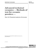
The basic requirements for pin-index, yoke-type valve
connections are shown in figure 1. Figures 2, 3 and 4
show alternative pin arrangements. Table 2 gives the
necessary dimensions.
Table 2. Basic dimensions for pin-index,
yoke-type valve connections
Symbol
Dimension
mm
Symbol
Dimension
mm
a
25
e
0,8 max
b
22,2 +0,4
0
f
0,8 max
c
16 min
g
D
7
h 2)
1,6 ± 0,4
20 ± 0,5
D1
2,4 ± 0,8
k
16,5 min
D2
4,75
11
44,5 min
D3
5,8 to 5,9
12
22 min
D4
6,3
13 3)
8 min
D5
6
14 3)
9,6 max
D6 1)
7 min
15
5,5+0,5
0
d
6,5
16
0
5,520,5
d1
4 ± 0,1
17
3 to 3,6
d2
5,4
18
15 min
d3
16 ± 0,5
9 ± 0,2
r
14,3 ± 0,07
r1
12 nom
r2
17,5 nom
+0,8
20,2
+0,2
0
+0,1
0
0
20,2
0
20,5
www.bzfxw.com
d4
0
20,2
0
20,1
1)
D6 is the dimension at the top of the yoke clamping screw
cone.
2) For h, q and q see clauses 5 and 6. As an alternative, these
1
dimensions may be given in order to satisfy the requirements of
6.1 g.
3) Applicable only if a projecting pressure relief device is used.
BSI 05-2001
Page 5
EN 850 : 1996
0
Ø 9 -0,5
8 min.
0
5,5 - 0,1
ØD1
X
l
1
l
2
=
h
l
3
l
8
X
=
ØD
c
l
4
Pressure relief device
www.bzfxw.com
Sealing washer
l
Detail of yoke
clamping screw
a
Section X-X
Dimensions in mm
Figure 1. Pin-index, yoke-type valve body and yoke
BSI 05-2001
Ød
k
Ø D4
Ø d3
b
e
Ød 4
ØD5
120°
100°
120°
100°
ØD
6
t
g
Yoke
7
Ø D3
Ø D6
r
Ød 2
Page 6
EN 850 : 1996
l
l
6
5
www.bzfxw.com
Figure 2. Pin-index, yoke-type valve connection Ð single pin
h
=
l
8
c
1
6
2
5
3
4
Ød 1
Ø D2
r
Ø D1
=
r
l
l
6
5
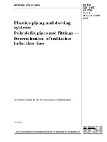
NOTE. Dimensional positions of holes and pins, numbered 1 to 6, are shown in figures 9 to 18.
Figure 3. Pin-index, yoke-type valve connection Ð two pins on a single arc
BSI 05-2001
Page 7
EN 850 : 1996
r2
r1
E
B
D
F
J
Ød 1
A
Ø D2
C
l
G
6
One pin only is
shown for clarity
H
l
5
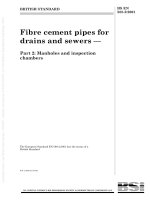
NOTE. Dimensional positions of holes and pins, identified by the letters A to J, are shown in table 3.
Figure 4. Pin-index, yoke-type valve connection Ð two pins on double arcs
6 Requirements for alternative designs of
pin-index, yoke-type valve connections
6.1 Requirements for the design of the
connecting yoke
The design of the connection shall meet the following
requirements:
a) a gas-tight seal shall only be possible when the
pins in the yoke match the corresponding holes in
the valve;
b) when the pins in the yoke do not correspond to
the holes in the valve, a gas-tight seal shall not be
possible and damage to the yoke, or the valve shall
be avoided;
c) pins shall be fixed or assembled in such a manner
that they cannot be removed by the user, or become
loose in service;
d) the sealing washer shall be a tight fit on the yoke
spigot;
e) the use of more than one sealing washer is not
permitted;
BSI 05-2001
f) the yoke shall be able to resist, without permanent
deformation, the load resulting from a torque of
50 N´m applied to the clamping screw or closing
device;
g) the dimensions of the yoke shall be such as to
limit the movement of the yoke, respective to the
valve, to a maximum of 6Ê about the long axis of the
valve, prior to pin engagement.
6.2 Examples of alternative constructions for
the connecting yoke
Three alternative designs of pin-index, yoke-type
connection are shown in figures 5 to 7.
Page 8
EN 850 : 1996
Y
s
Y
Y-Y
q
p
|
Symbol
Dimension
mm
p 1)
q 2)
44,5 max.
24+0,5
0
0,8 min.
s 3)
1) May be reduced to 35 mm if clearance is provided for
projecting pressure relief device.
2) See the note concerning dimension h in table 2.
3)Applicable
only if a projecting pressure relief device is used.
Figure 5. Screwed yoke
BSI 05-2001
s1
Page 9
EN 850 : 1996
View with clamping screw removed
q1
p1
Symbol
p1
q1 1)
s1
1)
2)
2)
Dimension
mm
30,2 max.
24+0,5
0
0,8 min.
See the note concerning dimension h in table 2.
Applicable only if a projecting pressure relief device is used.
Figure 6. Bolted yoke
BSI 05-2001
|
Page 10
EN 850 : 1996
NOTE. Cam is shown in the closed position
Figure 7. Cam operated yoke
BSI 05-2001
Page 11
EN 850 : 1996
7 Positions of holes and pins for
pin-index, yoke-type valve connections
The positions of holes and pins, for pin-index,
yoke-type valve connections, are shown in
figures 8 to 18 and in table 3.
7.1 Outlet connection with single pin system
Symbol
r
r
r
Machined face for washer
Dimension
mm
14,3 ± 0,07
Figure 8. Outlet connection for a nominal mixture of
50 % oxygen/50 % nitrous oxide (47,5 % < N2O < 52,5 %)
BSI 05-2001
Page 12
EN 850 : 1996
7.2 Outlet connections with two-pin/single-arc
system
t
t
Machined face for washer
2
5
u
t
u
w
2
u
w
w
Symbol
5
Dimension
mm
13,6 ± 0,07
4,4 ± 0,15
8,8 ± 0,07
Figure 9. Outlet connection for oxygen
BSI 05-2001
Page 13
EN 850 : 1996
2
6
6
u
t
t1
t
t
1
Machined face for washer
2
u
w1
w1
Symbol
Dimension
mm
t
t1
u
w1
13,6
12,4
4,4
11,55
±
±
±
±
0,07
0,07
0,15
0,07
Figure 10. Outlet connection for oxygen/carbon dioxide mixture (CO2 # 7 %)
BSI 05-2001
Page 14
EN 850 : 1996
2
4
t
2
w1
w2
t
t2
u
w2
4
u
u
Symbol
2
t
2
t
t
Machined face for washer
Dimension
mm
13,6 ± 0,07
14,2 ± 0,07
4,4 ± 0,15
5,9 ± 0,07
Figure 11. Outlet connection for oxygen/helium mixture (He # 80 %)
BSI 05-2001
Page 15
EN 850 : 1996
1
3
1
3
u1
u1
w3
w3
Symbol
Dimension
mm
t1
t2
u1
w3
12,4
14,2
1,5
5,65
±
±
±
±
0,07
0,07
0,15
0,07
Figure 12. Outlet connection for ethylene
BSI 05-2001
2
t
t1
2
t
t1
Machined face for washer
Page 16
EN 850 : 1996
5
3
u1
t
t2
u1
w2
5
u1
3
w2
w2
Symbol
2
t
t
2
t
t
Machined face for washer
Dimension
mm
13,6 ± 0,07
14,2 ± 0,07
1,5 ± 0,15
5,9 ± 0,07
Figure 13. Outlet connection for nitrous oxide (gas draw off)
BSI 05-2001