Bsi bs en 00737 2 1998 (2000)
Bạn đang xem bản rút gọn của tài liệu. Xem và tải ngay bản đầy đủ của tài liệu tại đây (219.82 KB, 30 trang )
BRITISH STANDARD
Medical gas pipeline
systems Ð
Part 2: Anaesthetic gas scavenging
disposal systems Ð Basic requirements
The European Standard EN 737-2:1998, with the incorporation of
amendment A1:1999, has the status of a British Standard
ICS 11.040.10
NO COPYING WITHOUT BSI PERMISSION EXCEPT AS PERMITTED BY COPYRIGHT LAW
| BS EN
|
|
| 737-2:1998
|
|
|
| Incorporating
| Amendment No. 1
|
|
|
|
|
|
|
|
|
|
|
|
|
|
|
|
|
|
|
|
|
|
|
|
|
|
|
|
|
|
|
|
|
|
|
|
|
|
|
|
|
|
|
|
|
|
|
|
|
|
|
|
|
|
|
|
|
|
|
|
|
|
|
|
|
|
|
|
|
|
|
|
|
|
|
|
|
|
|
|
|
|
|
|
|
|
|
|
|
|
|
|
|
|
|
|
|
|
|
|
|
|
|
|
|
|
|
|
|
|
|
|
|
|
|
|
|
|
|
|
BS EN 737-2:1998
National foreword
This British Standard is the English language version of EN 737-2:1998 including
amendment A1:1999. Together with BS EN 737-4:1998 and clause 111 of
BS EN 740:1998, it supersedes BS 6834:1987, which was withdrawn on
15 December 1998.
The UK participation in its preparation was entrusted by Technical Committee
CH/44, Anaesthetic machines, breathing attachments, medical gas pipeline systems
and hose assemblies, to Subcommittee CH/44/2, Medical gas supply systems, which
has the responsibility to:
Ð aid enquirers to understand the text;
Ð present to the responsible European committee any enquiries on the
interpretation, or proposals for change, and keep the UK interests informed;
Ð monitor related international and European developments and promulgate
them in the UK.
A list of organizations represented on this subcommittee can be obtained on request
to its secretary.
Rationales for some of the requirements of this standard are given in annex F. These
requirements are indicated by the letter ªRº after the clause number.
Cross-references
The British Standards which implement international or European publications
referred to in this document may be found in the BSI Standards Catalogue under the
section entitled ªInternational Standards Correspondence Indexº, or by using the
ªFindº facility of the BSI Standards Electronic Catalogue.
This British Standard does not purport to include all the necessary provisions of a
contract. Users of British Standards are responsible for their correct application.
Compliance with a British Standard does not of itself confer immunity
from legal obligations.
Summary of pages
This document comprises a front cover, an inside front cover, the EN title page,
pages 2 to 26, an inside back cover and a back cover.
The BSI copyright notice displayed in this document indicates when the document
was last issued.
Sidelining in this document indicates the most recent changes by amendment.
This British Standard, having
been prepared under the
direction of the Environment
Sector Board, was published
under the authority of the
Standards Board and comes into
effect on 15 September 1998
BSI 08-2000
ISBN 0 580 29763 2
Amendments issued since publication
Amd. No.
Date
Comments
10864
August 2000 Indicated by a sideline
EUROPEAN STANDARD
NORME EUROPÊENNE
EN 737-2
EUROPẰISCHE NORM
+ A1
April 1998
December 1999
ICS 11.040.10; 23.040.01
Descriptors: Medical equipment, gas distribution, medical gases, gas installation, gas pipelines, junctions, disposal, safety, definitions,
specifications, tests, agreements, marking, information
English version
Medical gas pipeline systems Ð
Part 2: Anaesthetic gas scavenging disposal
systems Ð Basic requirements
(includes amendment A1:1999)
SysteÁmes de distribution de gaz meÂdicaux Ð
Partie 2: SysteÁmes finals d'eÂvacuation des gaz
d'anestheÂsie Ð ReÁgles fondamentales
(inclut l'amendement A1:1999)
Rohrleitungssysteme fuÈr medizinische Gase Ð
Teil 2: Entsorgungssyteme von AnaÈsthesiegasFortleitungssystemen Ð Grundlegende
Anforderungen
(enthaÈlt AÈnderung A1:1999)
This European Standard was approved by CEN on 3 March 1998; amendment A1
was approved by CEN on 28 October 1999.
CEN members are bound to comply with the CEN/CENELEC Internal Regulations
which stipulate the conditions for giving this European Standard the status of a
national standard without any alteration. Up-to-date lists and bibliographical
references concerning such national standards may be obtained on application to
the Central Secretariat or to any CEN member.
This European Standard exists in three official versions (English, French, German).
A version in any other language made by translation under the responsibility of a
CEN member into its own language and notified to the Central Secretariat has the
same status as the official versions.
CEN members are the national standards bodies of Austria, Belgium, Czech
Republic, Denmark, Finland, France, Germany, Greece, Iceland, Ireland, Italy,
Luxembourg, Netherlands, Norway, Portugal, Spain, Sweden, Switzerland and
United Kingdom.
CEN
European Committee for Standardization
Comite EuropeÂen de Normalisation
EuropaÈisches Komitee fuÈr Normung
Central Secretariat: rue de Stassart 36, B-1050 Brussels
1998 CEN All rights of exploitation in any form and by any means reserved worldwide for CEN national
Members.
Ref. No. EN 737-2:1998 +A1:1999 E
Page 2
EN 737-2:1998
Foreword
This European Standard has been prepared by
Technical Committee CEN/TC 215, Respiratory and
anaesthetic equipment, the Secretariat of which is held
by BSI.
This European Standard shall be given the status of a
national standard, either by publication of an identical
text or by endorsement, at the latest by October 1998,
and conflicting national standards shall be withdrawn
at the latest by October 1998.
EN 737 consists of the following parts under the
general title Medical gas pipeline systems.
Ð Part 1: Terminal units for compressed medical
gases and vacuum;
Ð Part 2: Anaesthetic gas scavenging disposal
systems;
Ð Part 3: Pipelines for compressed medical gases
and vacuum;
Ð Part 4: Terminal units for anaesthetic gas
scavenging systems;
|
Ð Part 6: Dimensions of probes for terminal units
for compressed medical gases and vacuum.
This European Standard has been prepared under a
mandate given to CEN by the European Commission
and the European Free Trade Association, and
supports essential requirements of EU Directive(s).
For relationship with EU Directive(s), see informative
annex ZA, which is an integral part of this standard.
Annexes A, B, C, D, E, F, and ZA are informative.
According to the CEN/CENELEC Internal Regulations,
the national standards organizations of the following
countries are bound to implement this European
Standard: Austria, Belgium, Czech Republic, Denmark,
Finland, France, Germany, Greece, Iceland, Ireland,
Italy, Luxembourg, Netherlands, Norway, Portugal,
Spain, Sweden, Switzerland and the United Kingdom.
|
|
|
|
|
|
|
|
|
|
|
Foreword to amendment A1
This amendment EN 737-2:1998/A1:1999 to
EN 737-2:1998 has been prepared by Technical
Committee CEN/TC 215, Respiratory and anaesthetic
equipment, the Secretariat of which is held by BSI.
This amendment to the European Standard
EN 737-2:1998 shall be given the status of a national
standard, either by publication of an identical text or
by endorsement, at the latest by June 2000, and
conflicting national standards shall be withdrawn at
the latest by June 2000.
|
|
|
|
|
|
|
|
|
|
|
|
This amendment to the European Standard
EN 737-2:1998 has been prepared under a mandate
given to CEN by the European Commission and the
European Free Trade Association, and supports
essential requirements of EU Directive(s).
According to the CEN/CENELEC Internal Regulations,
the national standard organizations of the following
countries are bound to implement this European
Standard: Austria, Belgium, Czech Republic, Denmark,
Finland, France, Germany, Greece, Iceland, Ireland,
Italy, Luxembourg, Netherlands, Norway, Portugal,
Spain, Sweden, Switzerland and the United Kingdom.
Contents
Foreword
Introduction
1 Scope
2 Normative references
3 Definitions
4 General requirements
5 Power device
6 Indicating systems
7 Pipelines, connecting assemblies and
disposal hoses
8 Disposal system characteristics
9 Terminal units
10 Marking
11 Pipeline installation
12 Testing, commissioning and
certification
13 Information to be supplied by the
manufacturer
Annex A (informative) Guidelines for
general requirements for power devices
Annex B (informative) Procedure for testing
and commissioning
Annex C (informative) Typical forms for use
in testing and commissioning of AGS
disposal systems in accordance with
annex B
Annex D (informative) Recommended
minimum requirements for the organization
of maintenance
Annex E (informative) Bibliography
Annex F (informative) Rationale
Annex ZA (informative) Clauses of this
European Standard addressing essential
requirements or other provisions of
EU Directives
Page
2
3
3
3
3
5
5
5
5
6
6
6
7
8
8
12
12
13
25
25
25
26
BSI 08-2000
|
Page 3
EN 737-2:1998
Introduction
|
This part of this European Standard specifies basic
requirements for anaesthetic gas scavenging (AGS)
disposal systems.
This part of this European Standard seeks to ensure
the safe operation of anaesthetic gas scavenging
systems (AGSS). The AGSS comprises three main
parts, the transfer system, the receiving system and the
disposal system. The receiving system and the transfer
system are specified in EN 740. Type-specific
connections for terminal units are specified in
EN 737-4. In this part of this European Standard,
specifications and test procedures are given to ensure
compatibility between the components of the system.
A schematic diagram of typical anaesthetic gas
scavenging systems is shown in Figure 1.
1 Scope
|
This part of this European Standard specifies basic
requirements for the installation, function,
performance, documentation, testing and
commissioning of anaesthetic gas scavenging (AGS)
disposal systems to ensure patient and operator safety
by the safe removal of excess anaesthetic gases and
vapours from the clinical environment. It includes
basic requirements for the power device, pipeline
system and performance, and for
non-interchangeability between key components.
This part of this European Standard specifies:
a) the compatibility and safe performance between
the disposal system and the other components of the
AGSS by design, installation and commissioning;
b) the use of appropriate materials;
c) the testing of correct installation to ensure
achievement of the performance intended by the
manufacturer;
d) the marking of pipeline and components.
This part of this European Standard addresses only
those disposal systems which are intended to be
connected, via AGSS terminal units which comply with
EN 737-4, to a receiving system which complies with
EN 740.
2 Normative references
|
|
This European Standard incorporates by dated or
undated reference, provisions from other publications.
These normative references are cited at the
appropriate places in the text and the publications are
listed hereafter. For dated references, subsequent
amendments to or revisions of any of these
publications apply to this European Standard only
when incorporated in it by amendment or revision. For
undated references, the latest edition of the publication
referred to applies.
HD 384, Electrical installations of buildings.
EN 737-3, Medical gas pipeline systems Ð Part 3:
Pipelines for compressed medical gases and vacuum.
BSI 08-2000
EN 737-4, Medical gas pipeline systems Ð Part 4:
Terminal units for anaesthetic gas scavenging
systems.
EN 739, Low-pressure hose assemblies for use with
medical gases.
EN 740, Anaesthetic workstations and their
modules Ð Particular requirements.
EN 1441, Medical devices Ð Risk analysis.
3 Definitions
For the purposes of this part of this European
Standard, the following definitions apply.
3.1
AGSS Type 1 terminal unit
connection point between the receiving system and
disposal system at which an operator makes
connections and disconnections
3.2
AGSS Type 2 terminal unit
connection point between the power device or the
disposal hose and the remainder of the disposal system
at which an operator makes connections and
disconnections
3.3
air compressor system
source of supply with compressor(s), designed to
provide air for breathing and/or air for driving surgical
tools
3.4
anaesthetic gas scavenging system (AGSS)
system which is connected to the exhaust port(s) of an
anaesthetic workstation or which is integrated into an
anaesthetic workstation for the purpose of conveying
expired and/or excess anaesthetic gases to an
appropriate place of discharge
NOTE Functionally, an AGSS comprises three different parts, a
transfer system, a receiving system and a disposal system. These
three functionally discrete parts may be either separate or
sequentially combined in part or in total. In addition, one or more
parts of an AGSS may be sequentially combined with a breathing
system to include the transfer system or the transfer and receiving
system.
3.5
commissioning
proof of function, to verify that the agreed system
specification is met and is accepted by the user or the
representative of the user
3.6
design capacity
total flow of an AGS disposal system, taking into
account the diversity factor, i.e. the number of terminal
units which may be in use at the same time
|
|
Page 4
EN 737-2:1998
3.7
disposal hose
that part of an AGSS which transfers expired and/or
excess gases from the power device to the probe of an
AGSS Type 2 terminal unit
3.17
single fault condition
condition in which a single means for protection
against a safety hazard in equipment is defective, or a
single external abnormal condition is present
3.8
disposal system
means by which the expired and/or excess anaesthetic
gases are conveyed from the receiving system to an
appropriate place of discharge
3.18
shut-off valve; isolating valve
manual or automatic valve which prevents flow in both
directions when closed
NOTE A place of discharge may be, for example, the exterior of
a building or a non-recirculating extract ventilation system.
3.9
maximum operating pressure
maximum pressure at which a terminal unit is
designed to operate
NOTE Operating pressure for a Type 1 terminal unit is negative
and for a Type 2 terminal unit is positive.
3.10
maximum test pressure
maximum pressure to which a terminal unit is
designed to be subject during pipeline pressure testing
3.11
non-return valve
valve which permits flow in one direction only
3.12
power device
that part of a disposal system of an AGSS which
provides the gas flow for scavenging
3.13
probe
non-interchangeable male component designed for
acceptance by, and retention in, the socket
3.14
quick-connector
pair of non-threaded type-specific components which
can be easily and rapidly joined together by a single
action of one or both hands without the use of tools
3.15
receiving hose
that part of an AGSS which transfers expired and/or
excess gases from the receiving system to the disposal
system
3.16
receiving system
that part of an AGSS which provides an interface
between the transfer system and the disposal system,
and which may contain means of sub-atmospheric
and/or positive pressure relief
3.19
socket
that part of a terminal unit which is either integral or
attached to the base block by a type-specific interface,
and which contains the type-specific connection point
3.20
terminal unit
outlet assembly (inlet for vacuum and AGSS) in a
medical gas pipeline system at which an operator
makes connections and disconnections
3.21
terminal unit base block
that part of a terminal unit which is attached to the
disposal system
3.22
terminal unit check valve
valve which remains closed until opened by insertion
of an appropriate probe and which then permits flow
in either direction
3.23
transfer system
that part of an AGSS, which may or may not
incorporate tubing, which transfers expired and/or
excess anaesthetic gases from the exhaust port of the
anaesthetic breathing system and/or anaesthetic
ventilator to the receiving system, and which may
contain a means of pressure relief
3.24
transfer tube
that part of an AGSS which transfers expired and/or
excess gases from the anaesthetic breathing system
and/or anaesthetic ventilator to the receiving system
3.25
type-specific
having characteristics which prevent interchangeability
and thereby allow assignment to one type only
3.26
type-specific connection point
that part of a terminal unit which is the receptor for a
non-interchangeable type-specific probe and which is
either integral or attached to the base block by the
appropriate non-interchangeable type-specific device
BSI 08-2000
Page 5
EN 737-2:1998
4 General requirements
5 Power device
4.1 Safety
AGS disposal systems shall, when installed,
commissioned, operated in normal use and maintained
according to the instructions of the manufacturer,
cause no safety hazard which could be foreseen using
risk analysis procedures in accordance with EN 1441
and which is connected with their intended
application, in normal condition and in single fault
condition.
5.1 The power device shall be used solely to power
the AGS disposal system.
4.2R Alternative construction
AGS disposal system installations and components or
parts thereof, using materials or having forms of
construction different from those detailed in this part
of this European Standard, shall be accepted if it can
be demonstrated that an equivalent degree of safety is
obtained.
Such evidence shall be provided by the manufacturer.
4.3 Materials
4.3.1 The manufacturer shall disclose, upon request,
evidence of the corrosion resistance and of the
compatibility of the materials used for pipelines and
for all components of the system with anaesthetic
gases and vapours under the operating conditions
specified by the manufacturer.
NOTE Corrosion resistance includes resistance against the
influence of moisture and the surrounding materials in contact
with the components.
|
|
|
4.3.2R If copper pipes are used, they shall comply
with the requirements for copper tubing for pipelines
given in EN 737-3. Evidence shall be provided by the
manufacturer.
NOTE The requirement in 4.3.2 is intended to allow the use of
the same stock of copper pipes as is used for the installation of
pipeline systems for compressed medical gases and vacuum in
accordance with EN 737-3. It will be replaced by a normative
reference to a European Standard currently in preparation
(see prEN 13348:1998 in annex E).
4.3.3R All components of the system shall be supplied
clean and free from oil, grease and particulate matter
on the surfaces which come in contact with
anaesthetic gases and vapours.
Evidence shall be provided by the manufacturer.
|
|
5.2 The power device shall be one of the following:
a) an exhaust ejector, for each Type 1 terminal unit,
driven by compressed air from an air compressor
system and a pipeline system complying with
EN 737-3, provided with a means of adjusting the
flow from the receiving system through the Type 1
terminal unit to meet the requirements specified
in 8.1a (see Figure 2a);
b) an exhaust ejector for each Type 2 terminal unit,
driven by compressed air from an air compressor
system and a pipeline system complying with
EN 737-3, provided with a means of adjusting the
flow from the receiving system to meet the
requirements specified in 8.1b (see Figure 2b);
c) one or more fans, blowers or dedicated vacuum
pumps, provided with a means of adjusting and
controlling the vacuum level in the pipeline system
and therefore the flow through each Type 1 terminal
unit within the limits specified in 8.1a, regardless of
the number of terminal units in use (see Figure 2c).
|
Means shall be provided to indicate to the operator
that the power device is operating.
7 Pipelines, connecting assemblies and
disposal hoses
7.1 If the connecting assemblies or disposal hoses are
readily accessible to the operator, the connecting
assembly or the disposal hoses shall be type-specific
and the dimensions of its connectors shall not comply
with EN 739.
NOTE Examples of assemblies and hoses readily accessible to
the operator are those in a ceiling flexible pendant or a rigid
ceiling column with access panels.
7.2 If the connecting assemblies or disposal hoses are
not readily accessible to the operator without
significant disassembly of fixed equipment, the
connectors of the assembly need not be type-specific.
NOTE Examples of assemblies and hoses not readily accessible
to the operator are those in hinged-arm booms, tracks and
pendants.
4.3.4R If lubricants are used, they shall be compatible
with anaesthetic gases and vapours under the
operating conditions.
Evidence shall be provided by the manufacturer.
NOTE Examples of such assemblies are those used for isolation
of vibration, building movement and relative movement of the
pipelines.
BSI 08-2000
|
6 Indicating systems
NOTE 1 Any method of cleaning and degreasing can be used
which effectively removes all surface dirt and hydrocarbons, and
which leaves no residue itself. Chemical cleaning methods
normally require a subsequent washing and drying process to
remove residues.
NOTE 2 Examples of cleaning procedures are described
in prEN 13159:1997.
4.3.5 All precautions shall be taken to maintain
cleanliness during transportation, storage and
installation.
|
7.3 If the connecting assemblies are not normally
replaced during their life, the assembly need not be
type-specific.
7.4 Means shall be provided to prevent backflow of
waste gas to Type 2 terminal units.
NOTE This may be achieved by, for example, individual piping or
non-return valves.
|
Page 6
EN 737-2:1998
8 Disposal system characteristics
8.1 Characteristics
The characteristics of the AGS disposal system shall be
such that:
a) the flow through each Type 1 terminal unit or, if
not provided, at the interface point upstream of the
power device, (see Figure 1), shall not exceed
50 l/min when the resistance to flow is such as to
produce a pressure drop of 1 kPa, and shall not be
lower than 25 l/min when the resistance to flow is
such as to produce a pressure drop of 2 kPa;
|
NOTE see also EN 740, 111.4.5 in the formal vote version
of 1997);
the test for compliance is given in 8.2;
b) with a flow of 50 l/min through the socket of each
Type 2 terminal unit, if provided, the pressure drop
shall not exceed 7,5 kPa;
the test for compliance is given in 8.2.
8.2 Test method for flow and pressure drop
|
8.2.1 General
Adjust all flow control valves (if fitted) for the purpose
of controlling the flow at each terminal unit. Test each
terminal unit on the system as follows:
a) with only the terminal unit under test in use;
b) for systems with more than one terminal unit,
with all terminal units in use which are specified to
operate at the same time;
c) carry out tests with ambient air;
d) before any testing is carried out, label every
terminal unit in a system under test to indicate that
the system is under test and is not to be used;
e) use pressure measuring devices with a resolution
not greater than 10 % of the specified values to be
measured.
8.2.2 Test method for disposal systems fitted with
Type 1 terminal units
8.2.2.1 Apparatus
8.2.2.1.1 Test devices 1/50, each fitted with a
Type 1 probe and producing a pressure drop of 1 kPa at
a flow of 50 l/min.
|
NOTE This device simulates the resistance to flow of a receiving
system that complies with EN 740. See Figure 3 for an example.
8.2.2.1.2 Test devices 2/25, each fitted with a Type 1
probe and producing a pressure drop of 2 kPa at a
flow of 25 l/min.
NOTE See note to 8.2.2.1.1.
8.2.2.2 Procedure
8.2.2.2.1 If the test devices (8.2.2.1) are not
pre-calibrated, check that the flow and pressure drops
of each test device are in accordance with the
specified values when connected to a suitable source
of suction.
8.2.2.2.2 Activate the power device on the AGS
disposal system to be tested.
8.2.2.2.3 Insert a test device 1/50 (8.2.2.1.1) into each
terminal unit in turn, with all the other terminal units
closed. Record the flow on the test device at each
terminal unit.
8.2.2.2.4 Insert a test device 2/25 (8.2.2.1.2) into each
terminal unit in turn, with all the other terminal units
closed. Record the flow on the test device at each
terminal unit.
8.2.2.2.5 Insert a test device 1/50 (8.2.2.1.1) into each
of several terminal units up to the design capacity of
the AGS disposal system, with all the other terminal
units closed. Record the flow on each test device at
the same time.
8.2.2.2.6 Insert a test device 2/25 (8.2.2.1.2) into each
of several terminal units up to the design capacity of
the AGS disposal system, with all the other terminal
units closed. Record the flow on each test device at
the same time.
8.2.3 Test method for disposal systems fitted with
Type 2 terminal units
8.2.3.1 Test devices
8.2.3.1.1 Test devices 50, each fitted with a Type 2
probe and providing flows up to 50 l/min.
8.2.3.2 Procedure
8.2.3.2.1 Activate the power device on the AGS
disposal system to be tested.
8.2.3.2.2 Insert the test device (8.2.3.1.1) into each
terminal unit in turn, with all the other terminal units
closed.
Adjust the flow to (50 ± 5) l/min.
Record the pressure at the inlet to the terminal unit.
8.2.3.2.3 Insert a test device (8.2.3.1.1) into each of
several terminal units up to the design capacity of the
AGS disposal system with all the other terminal units
closed. Adjust each flow to (50 ± 5) l/min. Record the
pressure at the inlet to each terminal unit at the same
time.
9 Terminal units
Terminal units shall comply with EN 737-4.
10 Marking
10.1 Pipelines shall be marked ªAGSSº and shall have
arrows denoting the direction of flow adjacent to
valves, if fitted, at junctions and changes of direction,
before and after walls and partitions etc., at intervals of
no more than 10 m and adjacent to terminal units.
10.2 Connecting assemblies and disposal hoses shall
be marked ªAGSSº.
BSI 08-2000
Page 7
EN 737-2:1998
10.3 Marking shall be:
a) durable;
b) with letters not less than 6 mm high for the
pipelines, and not less than 2,5 mm high for
connecting assemblies and disposal hoses.
10.4 If colour coding is used, it shall be red magenta.
11.7 Damage due to contact with corrosive materials
shall be minimized by the use of impermeable
non-metallic materials applied to the outer surface of
the pipework in the areas where the contact can occur.
11.8 Allowances shall be made for expansion and
contraction of pipelines.
NOTE An example of red magenta is 3050-R40B in accordance
with SS 01 91 02.
11.9 Appropriate drain points shall be provided to
drain condensation.
10.5 Colour coding shall be durable. The test for
durability is given in 10.6.
11.10 Pipeline supports
10.6 Test the durability of marking and colour coding
as follows.
Rub markings and colour coding by hand, without
undue pressure, first for 15 s with a cloth rag soaked
with distilled water, then for 15 s with a cloth rag
soaked with methylated spirit, and then for 15 s with a
cloth rag soaked with isopropyl alcohol.
Carry out this test at ambient temperature.
11 Pipeline installation
11.1 Pipelines and electrical services shall be either:
a) run in separate compartments; or
b) separated by more than 50 mm.
11.2 The pipelines, if metallic, shall be bonded to an
earth terminal as near as possible to the point at which
the pipeline enters the building. The pipelines shall not
be used for earthing the electrical equipment. The
relevant parts of HD 384 shall apply.
11.3 Pipelines shall be protected from physical
damage.
NOTE Examples of physical damage are damage which might be
sustained from the movement of portable equipment such as
trolleys, stretchers and trucks in corridors and in other locations.
11.4 Unprotected pipelines shall not be installed in
areas of special hazard. If installation of pipelines in
such a location is unavoidable, the pipeline shall be
protected by an enclosure which will prevent the
escape of anaesthetic gas within the room should leaks
occur in the pipeline system installed in the area.
NOTE 1 Attention is drawn to national building requirements and
fire regulations.
NOTE 2 An example of a special hazard is an area where
flammable materials are stored.
11.5 If pipelines are placed in the same tunnel, trench
or duct with fuel pipelines, steam lines or other
services, they shall be separated by more than 50 mm.
Ducts in which pipelines are installed shall be
ventilated.
11.6 Pipelines shall not be installed in elevator shafts.
BSI 08-2000
11.10.1 Pipelines shall be supported at intervals to
prevent sagging or distortion.
NOTE Recommended intervals for rigid metallic pipes are given
in Table 1.
Table 1 Ð Recommended intervals between
supports for rigid metallic pipes
Outside
diameter
Maximum intervals between supports1)
mm
m
# 15
22 to 28
35 to 54
> 54
1,5
2,0
2,5
3,0
1) Shorter intervals may be required when using rigid
non-metallic pipes.
11.10.2 The supports shall ensure that the pipeline
cannot be displaced accidentally from its position.
11.10.3 The supports shall either be of
corrosion-resistant material, or shall be treated to
prevent corrosion. Means shall be provided to prevent
electrolytic corrosion.
11.10.4 Where pipelines cross electric cables, the
pipes shall be supported adjacent to the cables.
11.10.5 Pipelines shall not be used as support for, nor
shall they be supported by, other pipelines or conduits.
11.11 Pipeline joints
Except for threaded or special joints used in valves,
terminal units and where plastics materials are used,
all pipeline joints shall be brazed or welded. The
methods used for brazing or welding shall permit the
joints to maintain their mechanical characteristics up
to an ambient temperature of 450 8C.
11.12 The exhaust from the disposal system shall be
piped to the outside or into the exhaust conduit of a
non-recirculating ventilation system and shall be
provided with a means to prevent the ingress of
insects. It shall be in a position where risk of
contamination of occupied buildings is minimized.
Page 8
EN 737-2:1998
12 Testing, commissioning and
certification
|
|
|
|
|
|
NOTE 1 The aim of testing and commissioning of AGS disposal
systems is to verify that all safety aspects and performance
requirements of the systems are met.
NOTE 2 An example of a procedure and test methods for testing
and commissioning is given in annex B. Tests after completion of
installation should be carried out by the manufacturer and
witnessed by an authorized person qualified in the testing of
medical gas pipeline systems, who should certify the results of the
tests to the owner or client. The authorization can be given within
a certified quality system complying with appropriate parts of the
series EN ISO 9000 and EN 46000, or by a notified body.
NOTE 3 The results of tests showing details of the services and
areas tested should be part of the permanent record of the
hospital.
12.8 Disposal system exhaust
Verify that the exhaust from the disposal system
complies with 11.12.
12.9 Identification and labelling of the terminal
units
On satisfactory completion of the tests and procedures
described in 12.1 to 12.8, the labels indicating that the
system is under test shall be removed. At the same
time, check the correct identification and labelling of
each terminal unit.
12.10 Certification of the system
12.1 Leakage
12.10.1 Before an AGS disposal system is used, it
shall be certified in writing that all the requirements
of 12.1 to 12.9 have been met.
12.1.1 Pipelines downstream of the power device
shall be visually inspected for the integrity of all
connections.
12.10.2 The manufacturer shall certify that all
drawings and manuals, as specified in clause 13, have
been supplied to the owner or client.
12.1.2 Pipelines between a Type 1 terminal unit and a
power device shall be tested at a pressure of
70 kPa ± 10 %. The pressure drop in these sections,
after a test period of 15 min, shall be less than 10 kPa
with the terminal units blanked off.
12.2 Marking and support intervals of the
pipeline systems
The marking of the pipeline system shall meet the
requirements of clause 10, and the support intervals
shall meet the requirements of 11.10.
12.3 Mechanical function and inspection for
cleanliness of terminal units
It shall be demonstrated for each terminal unit that the
appropriate probe can be inserted, captured and
released.
All terminal units shall be inspected for the absence of
visible particulate matter.
12.4 Cross-connection
There shall be no cross-connection to any other
pipeline system.
12.5 Function of power devices
All power devices shall be tested for operation
according to the manufacturer's manuals and
specifications.
12.6 Flow and pressure drop
It shall be demonstrated that the flow and pressure
drop at each terminal unit are in accordance with
clause 8 when the AGS disposal system is operating at
the design capacity.
12.7 Indicating systems
Check that the indicating system complies with
clause 6.
13 Information to be supplied by the
manufacturer
13.1 Instruction manuals
The manufacturer shall provide to the owner
instructions for use of the complete system.
Particular attention shall be paid to:
Ð the power device;
Ð the indicating system;
Ð the danger of fire or explosion due to the use of
oil and grease in oxygen-enriched atmospheres.
13.2 Maintenance schedules
The manufacturer shall provide to the owner
instructions for recommended maintenance tasks and
their frequency, and a list of recommended spare parts.
13.3 ªAs installedº drawings
13.3.1 A set of ªas installedº mechanical drawings
which show the actual location and the diameters of
the pipeline systems shall be maintained during
construction, and shall be brought up to date as
variations are made. These drawings shall include
details which will enable buried or concealed pipelines
to be located.
13.3.2 Complete ªas installedº drawings, as specified
in 13.3.1, shall be supplied to the owner of the
pipeline system as a set of drawings, marked ªas
installedº, for inclusion as part of the permanent
record of the pipeline system.
NOTE If a pipeline system is altered subsequent to the transfer
of the drawings to the owner, then the ªas installedº drawings
specified in 13.3.2 should be brought up to date.
13.4 Electrical diagrams
Electrical diagrams for the complete installation shall
be provided by the manufacturer to the owner.
BSI 08-2000
Page 9
EN 737-2:1998
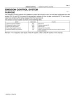
1 Apparatus including breathing system
and integral transfer/receiving system
and power device
2 Apparatus including breathing system
3 Transfer/receiving system and power
device
4 Apparatus including breathing system
and integral transfer/receiving system
5 Permanent or proprietary connector
6 Receiving hose
7 Breathing system or anaesthetic
ventilator
8 Transfer tube
9 Receiving system
10
11
12
13
14
15
16
17
18
19
Power device
Permanent connection
Discharge
Flexible hose or pendant
Disposal hose
Limit of breathing system
Limit of transfer system
Limit of receiving system
Limit of disposal system
Proprietary connection
(functionally specific)
20 30 mm conical connection
21 Type 1 terminal unit probe/socket
22 Type 2 terminal unit probe/socket
NOTE 1 Type 1 terminal unit probe/socket is for negative pressure. Type 2 terminal unit
probe/socket is for positive pressure (see note 2).
NOTE 2 The limit between the receiving system and the disposal system as shown may
not coincide with an actual physical limit such as a wall. In the arrangement shown a
terminal unit on a wall would be located on the inlet to the power device.
Figure 1 Ð Schematic diagram of typical AGSS connections
BSI 08-2000
Page 10
EN 737-2:1998
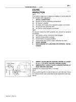
1
2
3
4
5
Compressed-air-driven power device
Vacuum pump/fan/blower power device
Flow regulating valve
Type 1 terminal unit
Type 2 terminal unit
6
7
8
9
Ambient air
Compressed air
Receiving system
Discharge
Figure 2 Ð Typical examples of power devices
BSI 08-2000
Page 11
EN 737-2:1998
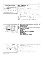
1
2
3
4
Type 1 probe
Flowmeter
Fixed orifice (1 kPa at 50 l/min and 2 kPa at 25 l/min)
Pressure-measuring device (for calibration only)
Figure 3 Ð Typical test devices for AGS disposal system characteristics
(with Type 1 terminal units)
BSI 08-2000
Page 12
EN 737-2:1998
Annex A (informative)
Guidelines for general requirements for
power devices
Typical forms for certification of the system are given
in annex C. A summary of the tests, which lists the
specification, procedure and report form for each test,
is given in Table B.1.
A.1 Only nominated persons should be authorized to
operate and attend the plant.
A.2 Services containing combustible gases or liquids
should not be permitted within the power device area.
A.3 Any heating system can be used to heat the
power device room, provided that no part of the
heating system which is in contact with the air within
the room exceeds a temperature of 225 8C.
A.4 All electrical fittings in power device rooms
should be located in fixed positions to minimize the
risk of physical damage.
A.5 Firefighting equipment should be provided.
A.6 The room should be well ventilated to the open
air, and ducting for such ventilation should not be
connected to ducting servicing any other building.
A.7 The doors or gate should be capable of being
locked. An emergency exit should be provided which
should be free from obstructions at all times. At any
time, all doors should be capable of being opened from
the inside without a key. All doors should open
outwards.
A.8 Power device rooms should:
a) comply with local building codes;
b) have concrete floors;
c) have a warning notice ªNO SMOKINGº or similar
clearly displayed on both sides of each door or gate.
A.9 The inlet of an air compressor should be located
in a position where there is minimal contamination
from internal combustion engine exhaust, vacuum
systems, anaesthetic gas scavenging systems,
ventilation system discharge and other contaminants.
The air intake should be provided with a means to
prevent the ingress of insects.
A.10 The exhaust from fans, blowers or vacuum
pumps should be piped to the outside and should be
provided with a means to prevent the ingress of
insects. It should be in a position where risk of
contamination of occupied buildings is minimized.
A.11 Subclauses A.1 to A.10 apply to power devices
which are centrally located. Power devices that are not
centrally located and may or may not be connected to
a pipeline system should be installed and serviced in
accordance with the instructions supplied by the
manufacturer.
B.2 General requirements for tests
Annex B (informative)
Procedure for testing and commissioning
B.1 General
This testing procedure is given as an example of how
the requirements of clause 12 can be verified so that
the system can be commissioned and certified. Other
procedures can be devised. In this procedure, the given
sequence of tests is important and should be followed.
|
B.2.1 Carry out tests with ambient air.
B.2.2 Before any testing is carried out, label every
terminal unit in a system under test to indicate that the
system is under test and is not to be used.
B.2.3 Use pressure-measuring devices with a
resolution not greater than 10 % of the specified values
to be measured.
B.3 Test methods for leakage
B.3.1 Inspection
Visually inspect the exhaust pipeline system for the
integrity of all connections.
B.3.2 Test for leakage
B.3.2.1 General conditions
Fit all terminal units and valves. Isolate the power
device from the pipeline. Open the valves and blank off
the Type 1 terminal units.
B.3.2.2 Procedure
Connect a suitable pressure-measuring device to the
system under test. Fill the system with test gas at a
pressure of 70 kPa ± 10 %. Record the pressure and,
after a period of 15 min, record the pressure again.
NOTE There is no allowance for temperature variation in this
test.
B.3.2.3 Results
Record the results on form C.1.
B.4 Test method for checking marking and
support intervals of the pipeline system
B.4.1 Procedure
Visually inspect that marking has been correctly placed
on the pipeline system, especially adjacent to
T-connectors and where the pipeline system passes
through walls or partitions. Check that the marking
complies with clause 10 and that the support intervals
comply with 11.10.
B.4.2 Results
Record the results on form C.2.
B.5 Test methods for mechanical function and
cleanliness of terminal units
B.5.1 Procedure
B.5.1.1 Inspect the test probes to ensure that they
conform to EN 737-4.
B.5.1.2 Insert a test probe into each terminal unit in
turn. Check that the probe can be inserted, captured
and released.
B.5.1.3 Check each terminal unit for the absence of
visible particulate matter.
B.5.2 Results
Record the results on form C.3.
BSI 08-2000
Page 13
EN 737-2:1998
B.6 Test method for checking for
cross-connection
B.10 Test method for the AGS disposal system
exhaust
B.6.1 Procedure
Visually inspect the pipeline system of the AGS
disposal system for cross-connection to any other
pipeline system.
B.10.1 Procedure
Verify that the exhaust from the AGS disposal system
is piped either to the outside or into the exhaust
conduit of a non-recirculating ventilation system, that it
is provided with a means to prevent the ingress of
insects and that the exhaust is in a position where the
risk of contamination of occupied buildings is
minimized.
B.6.2 Results
Record the results on form C.4.
B.7 Test method for function of power devices
B.7.1 Procedure
Test all power devices for operation according to the
manufacturer's manuals and specifications.
B.7.2 Results
Record the results on form C.5.
B.8 Test methods for flow and pressure drop
B.8.1 Procedure
The test methods given in 8.2 can be used.
B.8.2 Results
Record the results on form C.6/1 for Type 1 terminal
units and on form C.6/2 for Type 2 terminal units.
B.9 Test method for indicating systems
B.9.1 Procedure
Check that the means provided to indicate to the
operator that the power device is operating is
functioning.
B.9.2 Results
Record the results on form C.7.
B.10.2 Results
Record the results on form C.8.
B.11 Test method for identification and labelling
of the terminal units
B.11.1 Procedure
Check that the tests in B.1 to B.10 have been
completed satisfactorily.
Remove the label on each terminal unit which
indicates that the system is not to be used. Do not
remove these labels unless all preceding tests have
been completed satisfactorily. At the same time, check
the correct identification and labelling of each terminal
unit.
B.11.2 Results
Record the results on form C.9.
Annex C (informative)
Typical forms for use in testing and
commissioning of AGS disposal systems
in accordance with annex B
C.1 General
Annex C (on the following pages) gives examples of
forms for use in testing and commissioning AGS
disposal systems.
Table B.1 Ð Summary of tests
Test
number
Ð
1
2
3
4
5
6
7
8
9
BSI 08-2000
Description
Summary of tests done
Leakage
Marking and support intervals
Mechanical function and cleanliness
Cross-connection
Power devices
Flow and pressure drop:
Ð for Type 1 terminal units
Ð for Type 2 terminal units
Indicating system
Disposal system exhaust
Identification of terminal units
Specification
clause
Procedure
clause
Form
Ð
12.1
12.2
12.3
12.4
12.5
Ð
B.3
B.4
B.5
B.6
B.7
C.0
C.1
C.2
C.3
C.4
C.5
12.6
12.6
12.7
12.8
12.9
B.8
B.8
B.9
B.10
B.11
C.6/1
C.6/2
C.7
C.8
C.9
Page 14
EN 737-2:1998
Form C.0 (sheet of )
Summary of tests
This is to certify that the following tests and procedures have been carried out satisfactorily on the anaesthetic
gas scavenging disposal system at ........................................................................................................................ hospital.
Test number
1
2
3
4
5
6
7
8
9
Description
Form
Leakage
Marking and support intervals
Mechanical function and cleanliness
Cross-connection
Power devices
Flow and pressure drop
Ð for Type 1 terminal units
Ð for Type 2 terminal units
Indicating system
Disposal system exhaust
Identification of terminal units
Test completed on (date)
C.1
C.2
C.3
C.4
C.5
C.6/1
C.6/2
C.7
C.8
C.9
Construction labels removed
Contractor's representative
Status
Signed
Date
Name
Hospital representative
Status
Signed
Date
Name
Authorized person
Status
Signed
Date
Name
BSI 08-2000
Page 15
EN 737-2:1998
Anaesthetic gas scavenging disposal system
Form C.1 (sheet of )
Hospital
Scheme
Inspection and tests for leakage
This is to certify that the pipeline system was inspected and tested for leakage, and meets the requirements
of 12.1. At a test pressure of 70 kPa, the pressure drop after 15 min was .......... kPa (maximum permitted: 10 kPa).
Contractor's representative
Status
Signed
Date
Name
Hospital representative
Status
Signed
Date
Name
Authorized person
Status
Signed
Date
Name
BSI 08-2000
Page 16
EN 737-2:1998
Anaesthetic gas scavenging disposal system
Form C.2 (sheet of )
Hospital
Scheme
Inspection for marking and support intervals of the pipeline system
This is to certify that the pipeline system was inspected for marking and support intervals, and meets the
requirements of clause 10 and 11.10 respectively.
Contractor's representative
Status
Signed
Date
Name
Hospital representative
Status
Signed
Date
Name
Authorized person
Status
Signed
Date
Name
BSI 08-2000
Page 17
EN 737-2:1998
Anaesthetic gas scavenging disposal system
Form C.3 (sheet of )
Hospital
Scheme
Check of mechanical function and inspection for cleanliness of terminal units
This is certify that all terminal units were checked for mechanical function and inspected for cleanliness, and
meet the requirements of 12.3.
Contractor's representative
Status
Signed
Date
Name
Hospital representative
Status
Signed
Date
Name
Authorized person
Status
Signed
Date
Name
BSI 08-2000
Page 18
EN 737-2:1998
Anaesthetic gas scavenging disposal system
Form C.4 (sheet of )
Hospital
Scheme
Inspection for cross-connection
This is to certify that the pipeline system was inspected for cross-connection to any other pipeline system, and
meets the requirements of 12.4.
Contractor's representative
Status
Signed
Date
Name
Hospital representative
Status
Signed
Date
Name
Authorized person
Status
Signed
Date
Name
BSI 08-2000