Toyota RAV4 1994 2000 emission control system hệ thống kiểm soát khí thải trên xe toyota RAV4 đời 1998 2000
Bạn đang xem bản rút gọn của tài liệu. Xem và tải ngay bản đầy đủ của tài liệu tại đây (406.42 KB, 13 trang )
EC05E−01
−EMISSION CONTROL EMISSION CONTROL SYSTEM
EC−1
1996 RAV4 (RM447U)
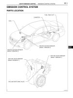
EMISSION CONTROL SYSTEM
PURPOSE
The emission control systems are installed to reduce the amount of HC, CO and NOx exhausted from the
engine ((3), (4) and (5)), to prevent the atmospheric release of blow−by gas−containing HC (1) and evapo-
rated fuel containing HC being released from the fuel tank (2).
The function of each system is shown in the following table.
System Abbreviation Function
(1) Positive Crankcase Ventilation
(2) Evaporative Emission Control
(3) Exhaust Gas Recirculation
(4) Three−Way Catalytic Converter
(5) Sequential Multiport Fuel Injection*
PCV
EVAP
EGR
TWC
SFI
Reduces HC
Reduces evaporated HC
Reduces NOx
Reduces HC, CO and NOx
Injects a precisely timed, optimum amount of fuel for reduced
exhaust emissions
Remark: * For inspection and repair of the SFI system, refer to the SFI section in this manual.
EC05F−04
EC−2
−EMISSION CONTROL PARTS LAYOUT AND SCHEMATIC DRAWING
1996 RAV4 (RM447U)
PARTS LAYOUT AND SCHEMATIC DRAWING
LOCATION
EC05G−03
−EMISSION CONTROL PARTS LAYOUT AND SCHEMATIC DRAWING
EC−3
1996 RAV4 (RM447U)
DRAWING
N00929
Clean Hose
Cylinder Head Side
N00930
Air Intake
Chamber
Side
Clean Hose
EC05H−04
P00989
EC−4
−EMISSION CONTROL POSITIVE CRANKCASE VENTILATION (PCV)
SYSTEM
1996 RAV4 (RM447U)
POSITIVE CRANKCASE
VENTILATION (PCV) SYSTEM
INSPECTION
1. REMOVE PCV VALVE
2. INSTALL CLEAN HOSE TO PCV VALVE
3. INSPECT PCV VALVE OPERATION
(a) Blow into the cylinder head side, and check that air
passes through easily.
CAUTION:
Do not suck air through the valve. Petroleum substances
inside the valve are harmful.
(b) Blow air into the intake manifold side, and check that air
passes through with difficulty.
If operation is not as specified, replace the PCV valve.
4. REMOVE CLEAN HOSE FROM PCV VALVE
5. REINSTALL PCV VALVE
6. VISUALLY INSPECT HOSES, CONNECTIONS AND
GASKETS
Check for cracks, leaks or damage.
EC05I−03
EC3069
Check Valve (Vacuum Valve)
Gasket
S01428
S01451
Port E
Port D
Port A
Compressed
Air
Port B
S01452
Port C
Port D
Port A
Compressed
Air
Port B
−EMISSION CONTROL EVAPORATIVE EMISSION (EVAP) CONTROL SYSTEM
EC−5
1996 RAV4 (RM447U)
EVAPORATIVE EMISSION (EVAP)
CONTROL SYSTEM
INSPECTION
1. VISUALLY INSPECT LINES AND CONNECTIONS
Look for loose connections, sharp bends or damage.
2. VISUALLY INSPECT FUEL TANK
Look for deformation, cracks or fuel leakage.
3. VISUALLY INSPECT FUEL TANK CAP
Check if the cap and/or gasket are deformed or damaged.
If necessary, repair or replace the cap.
4. DISCONNECT EVAP HOSES FROM CHARCOAL CAN-
ISTER
5. VISUALLY INSPECT CHARCOAL CANISTER
Look for cracks or damage.
6. CHECK FOR CLOGGED FILTER, AND STUCK CHECK
VALVE AND DIAPHRAGM
(a) Install a plug to port E.
(b) While holding port B closed, blow air (1.76 kPa, 18
gf/cm
2
, 0.26 psi) into port A and check that air flows from
port D.
(c) While holding port B and port D closed, blow air (1.76 kPa,
18 gf/cm
2
, 0.26 psi) into port A and check that air does not
flow from port C.
S01453
Port B
Port C
S01454
Port A
Port B
Port C
EC−6
−EMISSION CONTROL EVAPORATIVE EMISSION (EVAP) CONTROL SYSTEM
1996 RAV4 (RM447U)
(d) Apply vacuum (3.43 kPa, 26 mmHg, 1.01 in.Hg) to port B,
check that the vacuum does not decrease when port C is
closed, and check that the vacuum decreases when port
C is released.
(e) While holding port C closed, apply vacuum (1.23 kPa, 9.2
mmHg, 0.36 in.Hg) to port A and check that air flows into
port B.
If a problem is found, replace the charcoal canister.
(f) Remove the plug.
7. RECONNECT EVAP HOSES
8. INSPECT VSV FOR EVAP (See page SF−45)
9. INSPECT VSV FOR VAPOR PRESSURE SENSOR (See
page SF−47)
10. INSPECT VAPOR PRESSURE SENSOR (See page
SF−55)
EC05J−03
−EMISSION CONTROL EXHAUST GAS RECIRCULATION (EGR) SYSTEM
EC−7
1996 RAV4 (RM447U)
EXHAUST GAS RECIRCULATION (EGR) SYSTEM
COMPONENTS
EC05K−03
S01587
Cap
Filter
S01588
Vacuum
Gauge
S01261
DLC1
TE1
E1
SST
S01589
High Vacuum
at 2,500 rpm
Port R
Disconnect
HOT
EC−8
−EMISSION CONTROL EXHAUST GAS RECIRCULATION (EGR) SYSTEM
1996 RAV4 (RM447U)
INSPECTION
1. INSPECT AND CLEAN FILTER IN EGR VACUUM MOD-
ULATOR
(a) Remove the cap and filter.
(b) Check the filter for contamination or damage.
(c) Using compressed air, clean the filter.
(d) Reinstall the filter and cap.
HINT:
Install the filter with the coarser surface facing the atmospheric
side (outward).
2. INSTALL VACUUM GAUGE
Using a 3−way connector, connect a vacuum gauge to the hose
between the EGR valve and VSV.
3. INSPECT SEATING OF EGR VALVE
Start the engine and check that the engine starts and runs at
idle.
4. CONNECT TERMINALS TE1 AND E1 OF DLC1
Using SST, connect terminals TE1 and E1 of the DLC1
SST 09843−18020
5. INSPECT VSV OPERATION WITH COLD ENGINE
(a) The engine coolant temperature should be below
55°C (131°F).
(b) Check that the vacuum gauge indicates zero at 2,500
rpm.
6. INSPECT OPERATION OF VSV AND EGR VACUUM
MODULATOR WITH HOT ENGINE
(a) Warm up the engine to above 60°C (140°F).
(b) Check that the vacuum gauge indicates low vacuum at
2,500 rpm.
(c) Disconnect the vacuum hose port R of the EGR vacuum
modulator and connect port R directly to the intake man-
ifold with another hose.
(d) Check that the vacuum gauge indicates high vacuum at
2,500 rpm.
S01590
Disconnect
S01562
Engine Stopped
Air
S01561
Engine
2,500 rpm
Air
P02553
−EMISSION CONTROL EXHAUST GAS RECIRCULATION (EGR) SYSTEM
EC−9
1996 RAV4 (RM447U)
HINT:
As a large amount of exhaust gas enters, the engine will misfire
slightly.
7. REMOVE VACUUM GAUGE
Remove the vacuum gauge, and reconnect the vacuum hoses
to the proper locations.
8. INSPECT EGR VALVE
(a) Apply vacuum directly to the EGR valve with the engine
idling.
(b) Check that the engine runs rough or dies.
(c) Reconnect the vacuum hoses to the proper locations.
HINT:
As exhaust gas is increasingly recirculated, the engine will start
to misfire.
9. REMOVE SST FROM DLC1 (See page SF−1)
SST 09843−18020
10. INSPECT EGR VACUUM MODULATOR OPERATION
(a) Disconnect the vacuum hoses from ports P, Q and R of
the EGR vacuum modulator.
(b) Block ports P and R with your finger.
(c) Blow air into port Q, and check that the air passes through
to the air filter side freely.
(d) Start the engine, and maintain speed at 2,500 rpm.
(e) Repeat the above test. Check that there is a strong resis-
tance to air flow.
(f) Reconnect the vacuum hoses to the proper locations.
11. REMOVE THROTTLE BODY (See page SF−30)
12. REMOVE EGR VALVE
13. INSPECT EGR VALVE
Check for sticking and heavy carbon deposits.
If a problem is found, replace the valve.
S01616
EC−10
−EMISSION CONTROL EXHAUST GAS RECIRCULATION (EGR) SYSTEM
1996 RAV4 (RM447U)
14. REINSTALL EGR VALVE
(a) Install a 2 new gaskets and the EGR valve with the 2 nuts.
Torque: 13 N·m (130 kgf·cm, 9 ft·lbf)
(b) Install the EGR pipe with the 2 union nuts.
Torque: 59 N·m (600 kgf·cm, 43 ft·lbf)
15. REINSTALL THROTTLE BODY (See page SF−33)
EC0FI−02
−EMISSION CONTROL THREE−WAY CATALYTIC CONVERTER (TWC)
SYSTEM
EC−11
1996 RAV4 (RM447U)
THREE−WAY CATALYTIC CONVERTER (TWC) SYSTEM
COMPONENTS
EC−12
−EMISSION CONTROL THREE−WAY CATALYTIC CONVERTER (TWC)
SYSTEM
1996 RAV4 (RM447U)
EC05M−02
−EMISSION CONTROL THREE−WAY CATALYTIC CONVERTER (TWC)
SYSTEM
EC−13
1996 RAV4 (RM447U)
INSPECTION
1. CHECK CONNECTIONS FOR LOOSENESS OR DAMAGE
2. CHECK CLAMPS FOR WEAKNESS, CRACKS OR DAMAGE
3. CHECK FOR DENTS OR DAMAGE
If any part of the protector is damaged or dented to the extent that it contacts the TWC, repair or replace
it.
4. CHECK HEAT INSULATOR FOR DAMAGE
5. CHECK FOR ADEQUATE CLEARANCE BETWEEN CATALYTIC CONVERTER AND HEAT INSU-
LATOR