Bsi bs en 61853 1 2011
Bạn đang xem bản rút gọn của tài liệu. Xem và tải ngay bản đầy đủ của tài liệu tại đây (1.15 MB, 20 trang )
BS EN 61853-1:2011
BSI Standards Publication
Photovoltaic (PV) module
performance testing and
energy rating
Part 1: Irradiance and temperature performance
measurements and power rating
BRITISH STANDARD
BS EN 61853-1:2011
National foreword
This British Standard is the UK implementation of EN 61853-1:2011. It is
identical to IEC 61853-1:2011.
The UK participation in its preparation was entrusted to Technical Committee
GEL/82, Photovoltaic Energy Systems.
A list of organizations represented on this committee can be obtained on
request to its secretary.
This publication does not purport to include all the necessary provisions of a
contract. Users are responsible for its correct application.
© BSI 2011
ISBN 978 0 580 68063 2
ICS 27.160
Compliance with a British Standard cannot confer immunity from
legal obligations.
This British Standard was published under the authority of the Standards
Policy and Strategy Committee on 31 March 2011.
Amendments issued since publication
Amd. No.
Date
Text affected
BS EN 61853-1:2011
EUROPEAN STANDARD
EN 61853-1
NORME EUROPÉENNE
March 2011
EUROPÄISCHE NORM
ICS 27.160
English version
Photovoltaic (PV) module performance testing and energy rating Part 1: Irradiance and temperature performance measurements and power
rating
(IEC 61853-1:2011)
Essais de performance et caractéristiques
assignées d'énergie des modules
photovoltaïques (PV) Partie 1: Mesures de performance en
fonction de l'éclairement et de la
température, et caractéristiques de
puissance
(CEI 61853-1:2011)
Prüfung des Leistungsverhaltens von
photovoltaischen (PV-)Modulen und
Energiebemessung Teil 1: Leistungsmessung in Bezug auf
Bestrahlungsstärke und Temperatur sowie
Leistungsbemessung
(IEC 61853-1:2011)
This European Standard was approved by CENELEC on 2011-03-02. CENELEC members are bound to comply
with the CEN/CENELEC Internal Regulations which stipulate the conditions for giving this European Standard
the status of a national standard without any alteration.
Up-to-date lists and bibliographical references concerning such national standards may be obtained on
application to the Central Secretariat or to any CENELEC member.
This European Standard exists in three official versions (English, French, German). A version in any other
language made by translation under the responsibility of a CENELEC member into its own language and notified
to the Central Secretariat has the same status as the official versions.
CENELEC members are the national electrotechnical committees of Austria, Belgium, Bulgaria, Croatia, Cyprus,
the Czech Republic, Denmark, Estonia, Finland, France, Germany, Greece, Hungary, Iceland, Ireland, Italy,
Latvia, Lithuania, Luxembourg, Malta, the Netherlands, Norway, Poland, Portugal, Romania, Slovakia, Slovenia,
Spain, Sweden, Switzerland and the United Kingdom.
CENELEC
European Committee for Electrotechnical Standardization
Comité Européen de Normalisation Electrotechnique
Europäisches Komitee für Elektrotechnische Normung
Management Centre: Avenue Marnix 17, B - 1000 Brussels
© 2011 CENELEC -
All rights of exploitation in any form and by any means reserved worldwide for CENELEC members.
Ref. No. EN 61853-1:2011 E
BS EN 61853-1:2011
EN 61853-1:2011
-2-
Foreword
The text of document 82/613/FDIS, future edition 1 of IEC 61853-1, prepared by IEC TC 82, Solar
photovoltaic energy systems, was submitted to the IEC-CENELEC parallel vote and was approved by
CENELEC as EN 61853-1 on 2011-03-02.
Attention is drawn to the possibility that some of the elements of this document may be the subject of
patent rights. CEN and CENELEC shall not be held responsible for identifying any or all such patent
rights.
The following dates were fixed:
– latest date by which the EN has to be implemented
at national level by publication of an identical
national standard or by endorsement
(dop)
2011-12-02
– latest date by which the national standards conflicting
with the EN have to be withdrawn
(dow)
2014-03-02
Annex ZA has been added by CENELEC.
__________
Endorsement notice
The text of the International Standard IEC 61853-1:2011 was approved by CENELEC as a European
Standard without any modification.
__________
BS EN 61853-1:2011
-3-
EN 61853-1:2011
Annex ZA
(normative)
Normative references to international publications
with their corresponding European publications
The following referenced documents are indispensable for the application of this document. For dated
references, only the edition cited applies. For undated references, the latest edition of the referenced
document (including any amendments) applies.
NOTE When an international publication has been modified by common modifications, indicated by (mod), the relevant EN/HD
applies.
Publication
Year
Title
EN/HD
Year
IEC 60410
-
Sampling plans and procedures
for inspection by attributes
-
-
IEC 60891
2009
Photovoltaic devices - Procedures for
temperature and irradiance corrections to
measured I-V characteristics
EN 60891
2010
IEC 60904-1
-
Photovoltaic devices EN 60904-1
Part 1: Measurement of photovoltaic currentvoltage characteristics
-
IEC 60904-2
-
Photovoltaic devices Part 2: Requirements for reference solar
devices
EN 60904-2
-
IEC 60904-3
-
EN 60904-3
Photovoltaic devices Part 3: Measurement principles for terrestrial
photovoltaic (PV) solar devices with reference
spectral irradiance data
-
IEC 60904-5
-
Photovoltaic devices Part 5: Determination of the equivalent cell
temperature (ECT) of photovoltaic (PV)
devices by the open-circuit voltage method
EN 60904-5
-
IEC 60904-7
-
Photovoltaic devices EN 60904-7
Part 7: Computation of the spectral mismatch
correction for measurements of photovoltaic
devices
-
IEC 60904-9
-
Photovoltaic devices Part 9: Solar simulator performance
requirements
EN 60904-9
-
IEC 60904-10
-
Photovoltaic devices Part 10: Methods of linearity measurement
EN 60904-10
-
IEC 61215
2005
EN 61215
Crystalline silicon terrestrial photovoltaic
(PV) modules - Design qualification and type
approval
2005
IEC 61646
2008
Thin-film terrestrial photovoltaic (PV)
modules - Design qualification and type
approval
2008
EN 61646
BS EN 61853-1:2011
–2–
61853-1 IEC:2011
CONTENTS
INTRODUCTION ..................................................................................................................... 5
1
Scope and object .............................................................................................................. 6
2
Normative references ....................................................................................................... 6
3
Sampling .......................................................................................................................... 7
4
Marking ............................................................................................................................ 7
5
Testing and pass criteria .................................................................................................. 7
6
Report .............................................................................................................................. 8
7
Power rating conditions .................................................................................................... 8
8
7.1 General ................................................................................................................... 8
7.2 STC (Standard Test Conditions) .............................................................................. 9
7.3 NOCT (Nominal Operating Cell Temperature) .......................................................... 9
7.4 LIC (Low Irradiance Condition) ................................................................................ 9
7.5 HTC (High Temperature Condition) ......................................................................... 9
7.6 LTC (Low Temperature Condition) ........................................................................... 9
Procedure for irradiance and temperature performance measurements ............................ 9
9
8.1 Purpose .................................................................................................................. 9
8.2 Simplified procedure for linear modules ................................................................. 10
8.3 Procedure in natural sunlight with tracker .............................................................. 11
8.4 Procedure in natural sunlight without tracker ......................................................... 13
8.5 Procedure with a solar simulator ........................................................................... 13
Rating of power .............................................................................................................. 15
9.1
9.2
Interpolation of I sc , V oc , V max and P max .................................................................. 15
9.1.1 General ..................................................................................................... 15
9.1.2 Interpolation of I sc , V oc , V max and P max with respect to temperature .......... 15
9.1.3 Interpolation of I sc with respect to irradiance ............................................. 15
9.1.4 Interpolation of V oc with respect to irradiance ............................................ 15
9.1.5 Interpolation of P max with respect to irradiance .......................................... 16
9.1.6 Appropriateness of fitting method .............................................................. 16
Power rating .......................................................................................................... 16
Figure 1 – Positions for measuring the temperature of the test module behind the cells ....... 11
Table 1 – Summary of reference power conditions (at AM 1,5) ................................................ 9
Table 2 – I sc , P max, V oc and V max versus irradiance and temperature .................................... 10
BS EN 61853-1:2011
61853-1 IEC:2011
–5–
INTRODUCTION
This International Standard series establishes IEC requirements for evaluating PV module
performance based on power (watts), energy (watt-hours) and performance ratio (PR). It is
written to be applicable to all PV technologies including non-linear devices, but the
methodology does not take into account transient behaviour such as light induced changes
and/or thermal annealing.
Included in the IEC 61853 series of standards are: a guide to mapping module performance
over a wide range of temperature and irradiance conditions; methods for characterising
spectral and angular effects; definition of reference climatic profiles (temperature and
irradiance); methods for evaluating instantaneous power and energy results; and a method for
stating these results in the form of a numerical rating.
BS EN 61853-1:2011
–6–
61853-1 IEC:2011
PHOTOVOLTAIC (PV) MODULE
PERFORMANCE TESTING AND ENERGY RATING –
Part 1: Irradiance and temperature performance
measurements and power rating
1
Scope and object
This part of IEC 61853 describes requirements for evaluating PV module performance in
terms of power (watts) rating over a range of irradiances and temperatures. IEC 61853-2
describes test procedures for measuring the performance effect of angle of incidence; the
estimation of module temperature from irradiance, ambient temperature and wind speed; and
impact of spectral response on energy production. IEC 61853-3 describes the calculations of
PV module energy (watt-hours) ratings. IEC 61853-4 describes the standard time periods and
weather conditions that can be utilized for calculating standardized energy ratings.
The object of this part of IEC 61853 is to define a testing and rating system, which provides
the PV module power (watts) at maximum power operation for a set of defined conditions. A
second purpose is to provide a full set of characterization parameters for the module under
various values of irradiance and temperature. This set of measurements is required in order to
perform the module energy rating described in IEC 61853-3.
2
Normative references
The following referenced documents are indispensable for the application of this document.
For dated references, only the edition cited applies. For undated references, the latest edition
of the referenced document (including any amendments) applies.
IEC 60410, Sampling plans and procedures for inspection by attributes
IEC 60891:2009, Photovoltaic devices –
corrections to measured I-V characteristics
Procedures
for
temperature
and
irradiance
IEC 60904-1, Photovoltaic devices – Part 1: Measurement of photovoltaic current-voltage
characteristics
IEC 60904-2, Photovoltaic devices – Part 2: Requirements for reference solar devices
IEC 60904-3, Photovoltaic devices – Part 3: Measurement principles
photovoltaic (PV) solar devices with reference spectral irradiance data
for
terrestrial
IEC 60904-5, Photovoltaic devices – Part 5: Determination of equivalent cell temperature
(ECT) of photovoltaic (PV) devices by the open-circuit voltage method
IEC 60904-7, Photovoltaic devices – Part 7: Computation of spectral mismatch correction for
measurements of photovoltaic devices
IEC 60904-9, Photovoltaic devices – Part 9: Solar simulator performance requirements
IEC 60904-10, Photovoltaic devices – Part 10: Methods of linearity measurement
BS EN 61853-1:2011
61853-1 IEC:2011
IEC 61215:2005, Crystalline silicon
qualification and type approval
–7–
terrestrial
photovoltaic
(PV)
modules
–
Design
IEC 61646:2008, Thin film terrestrial photovoltaic (PV) modules – Design qualification and
type approval
3
Sampling
For performance qualification testing three modules shall be selected at random from a
production batch or batches in accordance with the procedure given in IEC 60410. The
modules shall be pre-conditioned in accordance with Clause 5 to ensure the stability of the
power values.
The modules shall have been manufactured from specified materials and components in
accordance with the relevant drawings and process sheets and shall have been subjected to
the manufacture’s normal inspection, quality control and production acceptance procedures.
The modules shall be complete in every detail and shall be accompanied by the
manufacturer’s handling and final assembly instructions regarding the recommended
installation of any diodes, frames, brackets, etc.
When the modules to be tested are prototypes of a new design and not from production, this
fact shall be noted in the test report (see Clause 6).
4
Marking
Each module shall carry the following clear and indelible markings:
–
name, monogram or symbol of the manufacturer;
–
type or model number;
–
serial number;
–
polarity of terminals or leads (colour coding is permissible);
–
nominal and minimum values of maximum output power at STC after preconditioning, as
specified by the manufacturer for the product type (see Clause 5).
The date and place of manufacture shall be marked on the module or be traceable from the
serial number.
For future production the power ratings for NOCT, LIC, HTC and LTC determined by this
standard as defined in Clause 7 and Table 1 and determined via the procedure in 9.2 shall be
marked on a label, or be stated in the manufacturer’s literature provided with each module of
this type.
5
Testing and pass criteria
The modules shall be subjected to the procedure for irradiance and temperature performance
measurements defined in Clause 8. In carrying out the tests, the manufacturer’s handling,
mounting and connection instructions shall be observed.
Special considerations: Preconditioning - Before beginning the measurements, the device
under test shall be stabilized by light soaking, as specified in IEC 61215 (Clause 5) or
IEC 61646 (10.19).
The values of STC power measured after preconditioning shall fall within the power range
specified by the manufacturer of this product.
BS EN 61853-1:2011
–8–
61853-1 IEC:2011
NOTE The pass/fail criteria must consider the laboratory uncertainty of the measurement. As an example, if the
laboratory extended uncertainty of the STC measurement is ±5 %, then a nominal nameplate rated power greater
than 95 % of the laboratory measured power would meet the pass criteria.
After generating the matrix of parameters in Section 8 the modules should be remeasured at
STC to verify that the performance is stable.
6
Report
Following completion of the procedure, a certified report of the performance tests, with
measured power characteristics shall be prepared by the test agency in accordance with the
procedures of ISO/IEC 17025. Each certificate or test report shall include at least the
following information:
a) a title;
b) name and address of the test laboratory and location where the calibration or tests were
carried out;
c) unique identification of the certification or report and of each page;
d) name and address of client, where appropriate;
e) description and identification of the item calibrated or tested;
f)
characterization and condition of the calibration or test item;
g) date of receipt of test item and date(s) of calibration or test, where appropriate;
h) identification of calibration or test method used;
i)
reference to sampling procedure, where relevant;
j)
any deviations from, additions to or exclusions from the calibration or test method, and
any other information relevant to a specific calibration or test, such as environmental
conditions;
k) a statement as to whether the simplified method in section 8 was used to complete the
matrix. If the simplified method was used, the test report should give the values of relative
temperature coefficients for maximum power and open circuit voltage for the two different
irradiances used to validate the use of the simplified method;
l)
measurements, examinations and derived results, including as a minimum table 2 for I sc ,
P max , V oc and V max , values of the module thermal coefficients αI, β I , the average power
and the values for each of the three test modules at all reference power conditions
(defined in section 7) and the temperature coefficient of module power (W) at the
maximum power point ( γ I );
m) a statement of the estimated uncertainty of the calibration or test result (where relevant);
n) a statement as to whether the measured STC power agrees with the manufacturer’s rated
power range within the test laboratories measurement uncertainty;
o) a signature and title, or equivalent identification of the person(s) accepting responsibility
for the content of the certificate or report, and the date of issue;
p) where relevant, a statement to the effect that the results relate only to the items calibrated
or tested;
q) a statement that the certificate or report shall not be reproduced except in full, without the
written approval of the laboratory.
7
7.1
Power rating conditions
General
The reference power conditions are shown in Table 1 and are described in more detail in the
following subclauses. The first three reference power conditions are defined in
IEC 61215/IEC 61646. The modules shall be tested and the maximum power determined for
BS EN 61853-1:2011
61853-1 IEC:2011
–9–
the following rating conditions. For each rating condition the Air Mass 1,5 spectral irradiance
distribution as given in IEC 60904-3 shall be used as well as normal incidence irradiance.
7.2
STC (Standard Test Conditions)
–
Cell temperature: 25 °C.
–
Irradiance: 1 000 W⋅m –2 .
7.3
NOCT (Nominal Operating Cell Temperature)
–
Cell temperature:
IEC 61646).
–
Irradiance: 800 W⋅m –2 .
7.4
NOCT (As determined in accordance with 10.5 of IEC 61215 or
LIC (Low Irradiance Condition)
–
Cell temperature: 25 °C.
–
Irradiance: 200 W⋅m –2 .
7.5
HTC (High Temperature Condition)
–
Cell temperature: 75 °C.
–
Irradiance: 1 000 W⋅m –2 .
7.6
LTC (Low Temperature Condition)
–
Cell temperature: 15 °C.
–
Irradiance: 500 W⋅m –2 .
Table 1 – Summary of reference power conditions (at AM 1,5)
Condition
STC
Irradiance
Temperature
W⋅m –2
°C
1 000
25 of cell
800
20 of ambient
200
25 of cell
1000
75 of cell
500
15 of cell
Standard Test Conditions
NOCT
Nominal Operating Cell
Temperature
(Determined according to
IEC 61215 or IEC 61646)
LIC
Low Irradiance Condition
HTC
High Temperature Condition
LTC
Low Temperature Condition
NOTE The conditions provided in this table may be measured directly as part of the performance matrix
defined in Clause 8.
8
8.1
Procedure for irradiance and temperature performance measurements
Purpose
To determine the impact of irradiance and temperature on module performance:
The power delivery of photovoltaic devices is a direct function of module temperature and
incident irradiance level. PV device performance is linear with temperature for many
BS EN 61853-1:2011
– 10 –
61853-1 IEC:2011
crystalline silicon materials, but no general relation can be given for thin film materials. The
short circuit current is often linear with respect to irradiance. The logarithmic variation of open
circuit voltage and nonlinear variations of fill factor with the irradiance often render the
maximum power a nonlinear function of light levels. Rather than using extensive modelling of
these processes, the relations will be measured as functions of irradiance and temperature.
NOTE If I sc of the module has been demonstrated to be linear (IEC 60904-10), I sc can be utilized as the
measurement of the irradiance level used in the test.
Matrices of module performance with respect to temperature and irradiance shall be
measured. Separate tables for I sc , V oc , V max and P max shall be generated using sufficient data
to assure statistical validity to the measurements (see 8.3.11 and 8.5.11). The tables for V oc
and V max are not utilized for energy ratings, but are useful characteristics of the module type
particularly for system design purposes.
Measurements need not be taken at exactly the irradiances and temperatures specified.
Translation of I-V curves from the actual irradiance and/or temperature values to the values
prescribed by the tables can be performed in accordance with IEC 60891. Such interpolation
should be over no more than 100 W⋅m –2 . All such interpolations shall be noted in the test
report and their impact on uncertainly shall be included in the uncertainly analysis.
Nevertheless, measurements shall be taken at or beyond the extremes of irradiance specified
in Table 2 within the measurement accuracy of the instrumentation and the constraints of
section 8.3.2.
A table of each of the parameters I sc , P max, V oc and V max, shall be made according to the
example in Table 2.
NOTE 1
To assess nonlinearities, measurements at 300 W/m 2 and 50 W/m 2 can be helpful.
NOTE 2
Tables of the parameters I max and Fill Factor (FF) can be generated from the four measured parameters.
Table 2 – I sc , P max , V oc and V max versus irradiance and temperature
Irradiance
Spectrum
W⋅m –2
Module temperature
15 °C
25 °C
50 °C
75 °C
1 100
AM1,5
NA
1 000
AM1,5
800
AM1,5
600
AM1,5
400
AM1,5
200
AM1,5
NA
NA
100
AM1,5
NA
NA
NA
AM1,5 is defined in IEC 60904-3.
There are four procedures for performing the test matrix of module performance with respect
to temperature and irradiance. The simplified procedure can only be utilized for linear
modules per IEC 60904-10. Two of the procedures are performed outdoors in natural sunlight
(one requiring a tracker and one that does not require a tracker). The fourth method is
performed indoors using a solar simulator.
8.2
Simplified procedure for linear modules
For modules that have been determined to be linear (per IEC 60904-10), the maximum power
dependence on irradiance and the maximum power dependence on temperature are
independent. In this case it is sufficient to measure:
BS EN 61853-1:2011
61853-1 IEC:2011
– 11 –
a) the parameters (I sc , V oc , P max and V max) dependence on irradiance at fixed temperature
over the range of 100 W⋅m –2 to 1 100 W⋅m –2 .
b) The parameters (I sc , V oc , P max and V max) dependence on temperature at two fixed
irradiances, one of which is between 800 W⋅m –2 and 1 000 W⋅m –2 and the second of
which is between 100 W⋅m –2 to 300 W⋅m –2 .
Compare the relative temperature coefficients for maximum power and open circuit voltage
determined from the two irradiance sets. If the two values for the relative temperature
coefficient of open circuit voltage agree within 10 % and the two values for the relative
temperature coefficient of maximum power agree within 15 %, the average of the two
temperature coefficients measured in b above can be utilized to fill out the tables. If not the
table should be completed by measuring at each set of conditions.
NOTE Because of its small value the relative temperature coefficient of short circuit current is not considered in
the above criteria.
8.3
8.3.1
Procedure in natural sunlight with tracker
Equipment required for this procedure is defined in IEC 60904-1.
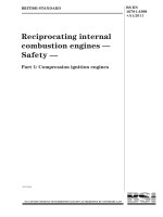
The temperature of the test module shall be measured at approximately the three positions
shown in Figure 1 (assuring that each position is directly behind a cell) and their values shall
be averaged. For crystalline silicon modules an alternate approach is to use the Equivalent
Cell Temperature measured using the method specified in IEC 60904-5.
IEC
2859/10
Figure 1 – Positions for measuring the temperature
of the test module behind the cells
8.3.2 Measurement in natural sunlight shall be performed over the range of irradiance
conditions occurring during the day. Short term irradiance variations caused by clouds, haze,
or smoke shall be less than ±1 % of the total irradiance as measured by the reference device
during the collection of each measurement point as specified in IEC 60904-1. The wind speed
should be less than 2 m⋅s –1 . To increase the range and improve the accuracy data should be
taken over at least three days.
8.3.3 Mount the reference device (as defined in IEC 60904-2) co-planar with the module on
the two-axis tracker such that both are normal to the direct solar beam within ±2°. Connect to
the necessary instrumentation.
NOTE The measurements described in the following sub-clauses should be made as expeditiously as possible
within a few hours on the same day to minimize the effect of changes in the spectral conditions. If not, spectral
corrections may be required.
BS EN 61853-1:2011
– 12 –
61853-1 IEC:2011
8.3.4 If the test module and reference device are equipped with temperature controls, set
the controls at the desired level. If temperature controls are not used:
a) shade the specimen from the sun and wind until its temperature is uniform within ± 2 °C of
the ambient air temperature, or
b) allow the test specimen to equilibrate to its stabilized temperature, or
c) pre-condition the test specimen to a point below the target temperature and then let the
module warm up naturally.
NOTE There may be differences between average cell temperature and average back temperature while the
module is warming up. IEC 60904-5 can be utilized to determine the temperature change by observing the variance
in open circuit voltage during the measurement time period.
8.3.5 Remove the shade (if used) and immediately take simultaneous readings of the test
module temperature and I-V performance characteristics (at a minimum I sc , V oc , V max and
P max), the temperature and short-circuit current of the reference device and the spectral
irradiance using the spectral radiometer (if a matched reference device is not utilized).
8.3.6 The irradiance, G o , shall be calculated from the measured current (I sc ) of the reference
device, and its calibration value at STC (I rc ). A correction should be applied to account for the
temperature of the reference device during the measurement, T m , using the specified relative
short circuit current temperature coefficient of the reference device, α rc .
Go =
Grc × I sc
× [1 – α rc (Tm – Trc )]
I rc
Where G rc is the irradiance at which the reference device was calibrated, usually 1000 W ⋅m –2
and T rc is the temperature at which the reference device was calibrated, usually 25 °C. If the
test specimen and reference device are not matched in spectral response, perform the
spectral correction on G o using the method from IEC 60904-7.
8.3.7 If the test parameter being varied is the irradiance, reduce the irradiance on the test
specimen to the desired level without affecting the spatial uniformity. There are various
methods by which to accomplish this:
a) using calibrated, uniform density mesh filters that do not change the spectral energy
distribution of the light. If this method is selected, the reference device should remain
uncovered by the filter during the operation to enable the incident irradiance to be
measured. In this case, the in plane irradiance is reduced by the filter calibration
parameter (fraction of light transmitted). The uniformity of the irradiance from the filters
should be verified using the uniformity procedure from IEC 60904-9 using the cell in the
test device to size the detector to determine the uniformity class. The results should be
provided in the test report.
b) using uncalibrated, uniform density mesh filters. If this method is selected, the reference
device should also be covered by the filter during the test. In this case, the reference
device must be linear in short circuit current in accordance with IEC 60904-10. In this case
in plane irradiance is reduced by the ratio of the reference device output to its calibration
value. The uniformity of the irradiance from the filters should be verified using the
uniformity procedure from IEC 60904-9 using the smallest device (either the cell in the test
device or the reference device) to size the detector to determine the uniformity class. The
results should be provided in the test report.
c) by controlling the angle of incidence. If this method is selected, the reference device
should have the same reflective properties as the test specimen, and should be mounted
co-planar with the test specimen within ±1°. In this case, the reference device must be
packaged like the test module (so it has the same angle of incidence behaviour) and be
linear in short circuit current in accordance with IEC 60904-10. Then the in plane
irradiance is reduced by the ratio of the reference device output to its calibration value.
BS EN 61853-1:2011
61853-1 IEC:2011
– 13 –
NOTE 1 The maximum filter mesh opening dimension shall be less than 1 % of the minimum linear dimension of
the reference device and the test specimen, or a variable error may occur due to positioning.
NOTE 2 The angle of incidence approach is sensitive to the angular difference between the test specimen and the
reference device at high angles. Therefore this method should not be utilized for angles above 60°.
8.3.8 If the test parameter being varied is the temperature, adjust the temperature by means
of a controller, or by alternately exposing and shading the module as required to achieve and
maintain the desired temperature for the naturally occurring irradiance levels. Alternately, the
test specimen may be allowed to warm-up naturally with the data recording procedure of 8.3.5
performed periodically during the warm-up.
8.3.9 Ensure that the test module and reference device temperature are stable and remain
constant within ±1 °C and that the irradiance as measured by the reference device remains
constant within ±2 % during the data recording period.
8.3.10 Repeat steps 8.3.5 through 8.3.9 until the performance measurements are completed
for the matrix of temperature and irradiance combinations as defined in Table 2. This means
that full matrices of I sc , V oc , V max and P max have been filled out.
8.3.11 A minimum of three measurements shall be made at each of the test conditions on a
minimum of three days. Continue to collect data until the standard deviations for all V oc , I sc
and P max values in the matrix are less than 5 %.
NOTE The angular response as well as the spectral response affect the measurements in outdoor conditions.
Spectral response can be corrected for by using spectrally matched reference cells or employing a
spectroradiometer and carrying out a spectral mismatch calculation. The angular effect can be eliminated by use of
a tracker
8.4
Procedure in natural sunlight without tracker
The second approach to collecting the outdoor data is to monitor the test modules outdoors
for extended time periods and then to extract the data necessary to populate the matrices.
This is a valid approach as long as the conditions specified in 8.3.2 are met. A tracker is not
required for this approach, but corrections for angular response may be required (see note in
8.3.11).
8.5
Procedure with a solar simulator
8.5.1
The equipment required for this procedure is defined in IEC 60904-1.
The PV reference device as defined in IEC 60904-2 shall be linear in short-circuit current as
defined in IEC 60904-10 over the irradiance range from 100 W⋅m –2 to 1100 W⋅m –2 . If methods
a), b), c) and e) from 8.5.7 are used the reference device shall be packaged via the same
method as the module under test.
The solar simulator should be a Class BBB or better solar simulator in accordance with
IEC 60904-9.
NOTE 1 The encapsulation system does effect the optical performance and spectral response of a PV device to
the degree that care must be taken to assure that the reference device used in this procedure is spectrally matched
to the module under test.
NOTE 2 Care should be taken if an emission lamp such as xenon is used for direct band gap and multijunciton
cells. As the band gap(s) changes due to temperature, it can pass through various emission lines in the lamp
spectrum and give rise to large shifts in performance. For multijunction devices, these band gap shifts can alter the
subcell current balancing and introduce additional shifts in performance.
NOTE 3 For a multijunction device, both the I sc and the FF are nonlinear functions of the simulator spectral
irradiance. Measurements made with solar simulators that are not spectrally adjustable can be expected to have
large errors because the subcell currents are not balanced with respect to each other. Errors above 15 % in the
current and power have been observed in commercial multijunction modules under a class AAA solar simulator.
BS EN 61853-1:2011
– 14 –
61853-1 IEC:2011
8.5.2 Mount the test device and the reference device co-planar in the test plane of the
simulator so that both are normal to the centre line of the beam within ±2°. Connect to the
necessary instrumentation.
8.5.3 If the test device and reference device are equipped with temperature controls, set the
controls at the desired level. If temperature controls are not used, allow the test module and
reference device to stabilize within ±2 °C of the chamber air temperature.
NOTE If measured in non-equilibrium temperature conditions the temperature sensors shall be placed as in
Figure 1.
8.5.4 Set the irradiance at the test plane to the upper limit of the range of interest using the
reference device.
8.5.5 Take simultaneous readings of the test device temperature and I-V performance
characteristics (at a minimum I sc , V oc , V max and P max), the temperature and short-circuit
current of the reference device and the spectral irradiance using the spectral radiometer (if a
matched reference device is not utilized).
8.5.6 The irradiance, G o , shall be calculated from the measured current (I sc ) of the PV
reference device, and its calibration value at STC (I rc ). A correction should be applied to
account for the temperature of the reference device, T m , using the specified relative short
circuit current temperature coefficient of the reference device, α rc .
Go =
Grc × I sc
× [1 – α rc (Tm – Trc )]
I rc
Where G rc is the irradiance at which the reference device was calibrated, usually 1000 W⋅m –2
and T rc is the temperature at which the reference device was calibrated, usually 25 °C. If the
test specimen and reference device are not matched in spectral response, perform the
spectral correction on G o using equation 1 in IEC 60904-7 to correct back to the AM1,5 global
spectrum for all irradiances.
8.5.7 If the test parameter being varied is the irradiance, reduce the irradiance on the test
device to the desired level without affecting the spatial uniformity or the spectral energy
distribution. Several methods to accomplish this are:
a) by increasing the distance between the test plane and the lamp. With the reference device
maintained in the same plane as the test specimen, in plane irradiance is reduced by the
ratio of the reference device output to its calibration value;
b) by the use of an optical lens. Care should be exercised to ensure that the lens does not
significantly change either the spectral energy distribution in the wavelength range in
which the test and reference specimens are responsive or the spatial uniformity in the test
plan. With the reference device maintained in the same plane as the test specimen, in
plane irradiance is reduced by the ratio of the reference device output to its calibration
value;
c) by controlling the angle of incidence. If this method is selected, the distance between the
lamp source and the specimen must be large to limit the irradiance change across the
tilted surface to 2 % or less. Also, if this method is selected, the reference device should
have the same reflective properties as the test specimen, and should be mounted coplanar with the test specimen. In this case, in plane irradiance is reduced by the ratio of
the reference device output to its calibration value;
d) using calibrated, uniform density mesh filters. If this method is selected, the reference
device must remain uncovered by the filter during the operation to enable the incident
irradiance to be measured. In this case, the in plane irradiance is reduced by the filter
calibration parameter (fraction of light transmitted);
BS EN 61853-1:2011
61853-1 IEC:2011
– 15 –
e) using uncalibrated, uniform density mesh filters. If this method is selected, the reference
device must also be covered by the filter during the test. In this case in plane irradiance is
reduced by the ratio of the reference device output to its calibration value;
f)
by determining the device characteristics at different irradiance levels during the decaying
tail of the flash of a pulsed solar simulator. This requires a spectral radiometer capable of
measuring the spectral irradiance of the simulator during the measurement or verification
that the reference device identified in a) is well matched to the test device over the range
of irradiances, spectral distribution and temperatures of interest.
NOTE 1 The maximum filter mesh opening dimension shall be less than 1 % of the minimum linear dimension of
the reference device and the test specimen, or a variable error may occur due to positioning.
NOTE 2 In method f the spectral match of the reference device to the test device should be verified by recording
the short circuit current of test and reference device output during a decaying pulse from the solar simulator. The
plot of the normalized relative ratio of the short circuit current of the test device to the reference device output
versus irradiance should be made and the deviation of the ratio from unity should not exceed 1 % in the irradiance
range of interest. Method f should not be used for multijunction devices.
8.5.8 If the test parameter being varied is the temperature, adjust the temperature by
appropriate means (see IEC 61215 or IEC 61646).
8.5.9 Ensure that the test module and reference device temperatures remain constant within
±1 °C during the test.
8.5.10 Repeat steps 8.5.5 through 8.5.9 until the performance measurements are completed
for the matrix of temperature and irradiance combinations as defined in Table 2.
8.5.11 A minimum of three measurements shall be made at each of the test conditions.
Continue to collect data until the standard deviations for all V oc , I sc and P max values in the
matrix are less than 5 %.
9
Rating of power
9.1
9.1.1
Interpolation of I sc , V oc , V max and P max
General
To determine I sc , V oc , V max and P max at intermediate values of irradiance and temperature
other than those directly measured, the following procedures should be used. The procedures
shall provide an estimate of the error (see 9.1.6).
9.1.2 Interpolation of I sc , V oc , V max and P max with respect to temperature
To determine I sc , V oc , V max and P max at intermediate values of temperature, use a linear
interpolation (regression) method with respect to the measured temperature dependence.
9.1.3 Interpolation of I sc with respect to irradiance
To determine I sc at intermediate values of irradiance, use a linear interpolation (regression)
method with respect to the measured irradiance dependence.
NOTE For non-linear devices the irradiance range used in the interpolation may have to be limited in order to
minimize the error.
9.1.4 Interpolation of V oc with respect to irradiance
To determine V oc at intermediate values of irradiance, data should be fitted to find ν 1 and ν 2 in
the following equation,
V ( G ) = v1 × ln( G ) + v2
BS EN 61853-1:2011
– 16 –
61853-1 IEC:2011
NOTE 1 This relation is based on the logarithmic variation of V oc with irradiance. Interpolation of V max can be
done using the same functional relationship as used for V oc with a new set of coefficients.
NOTE 2 For non-linear devices the irradiance range used in the interpolation may have to be limited in order to
minimize the error.
9.1.5 Interpolation of P max with respect to irradiance
To determine P max at intermediate values of irradiance, data from the region near the
irradiance of interest (within ±30 %) should be fitted to a polynomial as this should take into
account any non-linearity between data points.
NOTE In some cases it may be impossible to get a good fit to the whole P max versus I sc curve. In that case use
several points below and several points above the intermediate I sc value of interest. It may be necessary to take
more experimental readings at irradiances closer to the required value.
For linear devices, if the difference between the measured irradiances does not exceed 30 %,
linear interpolation may be used to obtain the value of P max at intermediate irradiance levels.
(See IEC 60891:2009, correction procedure 3.)
9.1.6 Appropriateness of fitting method
Check that the algorithms for 9.1.2 through 9.1.5 are valid by verifying that the global
minimum of the error function has been found (by investigating the error surfaces). If these
algorithms are not valid, other appropriate relations may be used.
9.2
Power rating
For each test module utilize Table 2 for P max and if necessary the interpolation procedure
given in clause 9.1.5 to determine P max at each of the reference power conditions as defined
in Clause 7 and Table 1. For each module type the reported reference power conditions
(except for STC) shall be the average of the values determined for the three test modules.
This average plus the range of determined values shall be reported and utilized for markings
in Clause 4.
____________
This page deliberately left blank
NO COPYING WITHOUT BSI PERMISSION EXCEPT AS PERMITTED BY COPYRIGHT LAW
British Standards Institution (BSI)
BSI is the national body responsible for preparing British Standards and other
standards-related publications, information and services.
BSI is incorporated by Royal Charter. British Standards and other standardization
products are published by BSI Standards Limited.
About us
Revisions
We bring together business, industry, government, consumers, innovators
and others to shape their combined experience and expertise into standards
-based solutions.
Our British Standards and other publications are updated by amendment or revision.
The knowledge embodied in our standards has been carefully assembled in
a dependable format and refined through our open consultation process.
Organizations of all sizes and across all sectors choose standards to help
them achieve their goals.
Information on standards
We can provide you with the knowledge that your organization needs
to succeed. Find out more about British Standards by visiting our website at
bsigroup.com/standards or contacting our Customer Services team or
Knowledge Centre.
Buying standards
You can buy and download PDF versions of BSI publications, including British
and adopted European and international standards, through our website at
bsigroup.com/shop, where hard copies can also be purchased.
If you need international and foreign standards from other Standards Development
Organizations, hard copies can be ordered from our Customer Services team.
Subscriptions
Our range of subscription services are designed to make using standards
easier for you. For further information on our subscription products go to
bsigroup.com/subscriptions.
With British Standards Online (BSOL) you’ll have instant access to over 55,000
British and adopted European and international standards from your desktop.
It’s available 24/7 and is refreshed daily so you’ll always be up to date.
You can keep in touch with standards developments and receive substantial
discounts on the purchase price of standards, both in single copy and subscription
format, by becoming a BSI Subscribing Member.
PLUS is an updating service exclusive to BSI Subscribing Members. You will
automatically receive the latest hard copy of your standards when they’re
revised or replaced.
To find out more about becoming a BSI Subscribing Member and the benefits
of membership, please visit bsigroup.com/shop.
With a Multi-User Network Licence (MUNL) you are able to host standards
publications on your intranet. Licences can cover as few or as many users as you
wish. With updates supplied as soon as they’re available, you can be sure your
documentation is current. For further information, email
BSI Group Headquarters
389 Chiswick High Road London W4 4AL UK
We continually improve the quality of our products and services to benefit your
business. If you find an inaccuracy or ambiguity within a British Standard or other
BSI publication please inform the Knowledge Centre.
Copyright
All the data, software and documentation set out in all British Standards and
other BSI publications are the property of and copyrighted by BSI, or some person
or entity that owns copyright in the information used (such as the international
standardization bodies) and has formally licensed such information to BSI for
commercial publication and use. Except as permitted under the Copyright, Designs
and Patents Act 1988 no extract may be reproduced, stored in a retrieval system
or transmitted in any form or by any means – electronic, photocopying, recording
or otherwise – without prior written permission from BSI. Details and advice can
be obtained from the Copyright & Licensing Department.
Useful Contacts:
Customer Services
Tel: +44 845 086 9001
Email (orders):
Email (enquiries):
Subscriptions
Tel: +44 845 086 9001
Email:
Knowledge Centre
Tel: +44 20 8996 7004
Email:
Copyright & Licensing
Tel: +44 20 8996 7070
Email: