Iec 60730 2 9 2011
Bạn đang xem bản rút gọn của tài liệu. Xem và tải ngay bản đầy đủ của tài liệu tại đây (654.48 KB, 128 trang )
®
Edition 3.1
2011-06
INTERNATIONAL
STANDARD
NORME
INTERNATIONALE
Automatic electrical controls for household and similar use –
Part 2-9: Particular requirements for temperature sensing controls
IEC 60730-2-9:2008+A1:2011
Dispositifs de commande électrique automatiques à usage domestique
et analogue –
Partie 2-9: Règles particulières pour les dispositifs de commande
thermosensibles
colour
inside
Copyrighted material licensed to BR Demo by Thomson Reuters (Scientific), Inc., subscriptions.techstreet.com, downloaded on Nov-28-2014 by James Madison. No further reproduction or distribution is permitted. Uncontrolled when printe
IEC 60730-2-9
Copyright © 2011 IEC, Geneva, Switzerland
All rights reserved. Unless otherwise specified, no part of this publication may be reproduced or utilized in any form or by
any means, electronic or mechanical, including photocopying and microfilm, without permission in writing from either IEC or
IEC's member National Committee in the country of the requester.
If you have any questions about IEC copyright or have an enquiry about obtaining additional rights to this publication,
please contact the address below or your local IEC member National Committee for further information.
Droits de reproduction réservés. Sauf indication contraire, aucune partie de cette publication ne peut être reproduite
ni utilisée sous quelque forme que ce soit et par aucun procédé, électronique ou mécanique, y compris la photocopie
et les microfilms, sans l'accord écrit de la CEI ou du Comité national de la CEI du pays du demandeur.
Si vous avez des questions sur le copyright de la CEI ou si vous désirez obtenir des droits supplémentaires sur cette
publication, utilisez les coordonnées ci-après ou contactez le Comité national de la CEI de votre pays de résidence.
IEC Central Office
3, rue de Varembé
CH-1211 Geneva 20
Switzerland
Email:
Web: www.iec.ch
About the IEC
The International Electrotechnical Commission (IEC) is the leading global organization that prepares and publishes
International Standards for all electrical, electronic and related technologies.
About IEC publications
The technical content of IEC publications is kept under constant review by the IEC. Please make sure that you have the
latest edition, a corrigenda or an amendment might have been published.
Catalogue of IEC publications: www.iec.ch/searchpub
The IEC on-line Catalogue enables you to search by a variety of criteria (reference number, text, technical committee,…).
It also gives information on projects, withdrawn and replaced publications.
IEC Just Published: www.iec.ch/online_news/justpub
Stay up to date on all new IEC publications. Just Published details twice a month all new publications released. Available
on-line and also by email.
Electropedia: www.electropedia.org
The world's leading online dictionary of electronic and electrical terms containing more than 20 000 terms and definitions
in English and French, with equivalent terms in additional languages. Also known as the International Electrotechnical
Vocabulary online.
Customer Service Centre: www.iec.ch/webstore/custserv
If you wish to give us your feedback on this publication or need further assistance, please visit the Customer Service
Centre FAQ or contact us:
Email:
Tel.: +41 22 919 02 11
Fax: +41 22 919 03 00
A propos de la CEI
La Commission Electrotechnique Internationale (CEI) est la première organisation mondiale qui élabore et publie des
normes internationales pour tout ce qui a trait à l'électricité, à l'électronique et aux technologies apparentées.
A propos des publications CEI
Le contenu technique des publications de la CEI est constamment revu. Veuillez vous assurer que vous possédez
l’édition la plus récente, un corrigendum ou amendement peut avoir été publié.
Catalogue des publications de la CEI: www.iec.ch/searchpub/cur_fut-f.htm
Le Catalogue en-ligne de la CEI vous permet d’effectuer des recherches en utilisant différents critères (numéro de référence,
texte, comité d’études,…). Il donne aussi des informations sur les projets et les publications retirées ou remplacées.
Just Published CEI: www.iec.ch/online_news/justpub
Restez informé sur les nouvelles publications de la CEI. Just Published détaille deux fois par mois les nouvelles
publications parues. Disponible en-ligne et aussi par email.
Electropedia: www.electropedia.org
Le premier dictionnaire en ligne au monde de termes électroniques et électriques. Il contient plus de 20 000 termes et
définitions en anglais et en franỗais, ainsi que les termes ộquivalents dans les langues additionnelles. Egalement appelé
Vocabulaire Electrotechnique International en ligne.
Service Clients: www.iec.ch/webstore/custserv/custserv_entry-f.htm
Si vous désirez nous donner des commentaires sur cette publication ou si vous avez des questions, visitez le FAQ du
Service clients ou contactez-nous:
Email:
Tél.: +41 22 919 02 11
Fax: +41 22 919 03 00
Copyrighted material licensed to BR Demo by Thomson Reuters (Scientific), Inc., subscriptions.techstreet.com, downloaded on Nov-28-2014 by James Madison. No further reproduction or distribution is permitted. Uncontrolled when printe
THIS PUBLICATION IS COPYRIGHT PROTECTED
®
Edition 3.1
2011-06
INTERNATIONAL
STANDARD
NORME
INTERNATIONALE
colour
inside
Automatic electrical controls for household and similar use –
Part 2-9: Particular requirements for temperature sensing controls
Dispositifs de commande électrique automatiques à usage domestique
et analogue –
Partie 2-9: Règles particulières pour les dispositifs de commande
thermosensibles
INTERNATIONAL
ELECTROTECHNICAL
COMMISSION
COMMISSION
ELECTROTECHNIQUE
INTERNATIONALE
PRICE CODE
CODE PRIX
ICS 97.120
® Registered trademark of the International Electrotechnical Commission
Marque déposée de la Commission Electrotechnique Internationale
CQ
ISBN 978-2-88912-511-1
Copyrighted material licensed to BR Demo by Thomson Reuters (Scientific), Inc., subscriptions.techstreet.com, downloaded on Nov-28-2014 by James Madison. No further reproduction or distribution is permitted. Uncontrolled when printe
IEC 60730-2-9
60730-2-9 IEC:2008+A1:2011
CONTENTS
FOREWORD ........................................................................................................................... 4
1
Scope and normative references ....................................................................................... 7
2
Definitions ........................................................................................................................ 8
3
General requirements ..................................................................................................... 10
4
General notes on tests .................................................................................................... 10
5
Rating ............................................................................................................................. 10
6
Classification .................................................................................................................. 10
7
Information ..................................................................................................................... 11
8
Protection against electric shock ..................................................................................... 13
9
Provision for protective earthing ...................................................................................... 13
10 Terminals and terminations ............................................................................................. 13
11 Constructional requirements ........................................................................................... 13
12 Moisture and dust resistance .......................................................................................... 16
13 Electric strength and insulation resistance ....................................................................... 17
14 Heating ........................................................................................................................... 17
15 Manufacturing deviation and drift .................................................................................... 18
16 Environmental stress ...................................................................................................... 19
17 Endurance ...................................................................................................................... 19
18 Mechanical strength ........................................................................................................ 25
19 Threaded parts and connections ..................................................................................... 27
20 Creepage distances, clearances and distances through solid insulation ........................... 27
21 Fire hazard testing .......................................................................................................... 27
22 Resistance to corrosion .................................................................................................. 27
23 Electromagnetic compatibility (EMC) requirements – emission ........................................ 27
24 Components ................................................................................................................... 28
25 Normal operation ............................................................................................................ 28
26 Electromagnetic compatibility (EMC) requirements – immunity ........................................ 28
27 Abnormal operation......................................................................................................... 28
28 Guidance on the use of electronic disconnection ............................................................. 28
Annexes ................................................................................................................................ 29
Annex H (normative) Requirements for electronic controls .................................................... 29
Annex J (normative) Requirements for controls using thermistors ......................................... 34
Annex AA (informative) Maximum manufacturing deviation and drift...................................... 35
Annex BB (informative) Time factor ...................................................................................... 36
Annex CC (informative) Number of cycles ............................................................................ 39
Annex DD (normative) Controls for use in agricultural confinement buildings ........................ 40
Annex EE (informative) Guide to the application of temperature sensing controls within
the scope of IEC 60730-2-9 ................................................................................................... 44
Copyrighted material licensed to BR Demo by Thomson Reuters (Scientific), Inc., subscriptions.techstreet.com, downloaded on Nov-28-2014 by James Madison. No further reproduction or distribution is permitted. Uncontrolled when printe
–2–
–3–
Figure 11.4.13.102 – Impact tool ........................................................................................... 15
Figure 17.101.3 – Aluminium cylinder for temperature change method ................................... 25
Figure BB.1 – Determination of time factor in the case of a sudden temperature change ........ 37
Figure BB.2 – Determination of time factor in the case of a linear rise of test-bath
temperature .......................................................................................................................... 38
Figure EE.1 – Thermostat ..................................................................................................... 53
Figure EE.2 – Self-resetting temperature limiter..................................................................... 54
Figure EE.3 – Non-self-resetting temperature limiter .............................................................. 54
Figure EE.4 – Self-resetting thermal cut-out .......................................................................... 56
Figure EE.5 – Manual reset thermal cut-out ........................................................................... 56
Figure EE.6 – Single operation device ................................................................................... 58
Figure EE.7 – Three-stage control system ............................................................................. 59
Table H.26.2.101 – Compliance criteria ................................................................................. 31
Table BB.1 – Method to determine and verify time factor values (see 11.101) ........................ 38
Table EE.1 – Typical examples of the classification of temperature sensing controls in
accordance with IEC 60730-2-9 ............................................................................................. 60
Copyrighted material licensed to BR Demo by Thomson Reuters (Scientific), Inc., subscriptions.techstreet.com, downloaded on Nov-28-2014 by James Madison. No further reproduction or distribution is permitted. Uncontrolled when printe
60730-2-9 IEC:2008+A1:2011
60730-2-9 IEC:2008+A1:2011
INTERNATIONAL ELECTROTECHNICAL COMMISSION
____________
AUTOMATIC ELECTRICAL CONTROLS
FOR HOUSEHOLD AND SIMILAR USE –
Part 2-9: Particular requirements
for temperature sensing controls
FOREWORD
1) The International Electrotechnical Commission (IEC) is a worldwide organization for standardization comprising
all national electrotechnical committees (IEC National Committees). The object of IEC is to promote
international co-operation on all questions concerning standardization in the electrical and electronic fields. To
this end and in addition to other activities, IEC publishes International Standards, Technical Specifications,
Technical Reports, Publicly Available Specifications (PAS) and Guides (hereafter referred to as “IEC
Publication(s)”). Their preparation is entrusted to technical committees; any IEC National Committee interested
in the subject dealt with may participate in this preparatory work. International, governmental and nongovernmental organizations liaising with the IEC also participate in this preparation. IEC collaborates closely
with the International Organization for Standardization (ISO) in accordance with conditions determined by
agreement between the two organizations.
2) The formal decisions or agreements of IEC on technical matters express, as nearly as possible, an international
consensus of opinion on the relevant subjects since each technical committee has representation from all
interested IEC National Committees.
3) IEC Publications have the form of recommendations for international use and are accepted by IEC National
Committees in that sense. While all reasonable efforts are made to ensure that the technical content of IEC
Publications is accurate, IEC cannot be held responsible for the way in which they are used or for any
misinterpretation by any end user.
4) In order to promote international uniformity, IEC National Committees undertake to apply IEC Publications
transparently to the maximum extent possible in their national and regional publications. Any divergence
between any IEC Publication and the corresponding national or regional publication shall be clearly indicated in
the latter.
5) IEC itself does not provide any attestation of conformity. Independent certification bodies provide conformity
assessment services and, in some areas, access to IEC marks of conformity. IEC is not responsible for any
services carried out by independent certification bodies.
6) All users should ensure that they have the latest edition of this publication.
7) No liability shall attach to IEC or its directors, employees, servants or agents including individual experts and
members of its technical committees and IEC National Committees for any personal injury, property damage or
other damage of any nature whatsoever, whether direct or indirect, or for costs (including legal fees) and
expenses arising out of the publication, use of, or reliance upon, this IEC Publication or any other IEC
Publications.
8) Attention is drawn to the Normative references cited in this publication. Use of the referenced publications is
indispensable for the correct application of this publication.
9) Attention is drawn to the possibility that some of the elements of this IEC Publication may be the subject of
patent rights. IEC shall not be held responsible for identifying any or all such patent rights.
This consolidated version of IEC 60730-2-9 consists of the third edition (2008)
[documents 72/763/FDIS and 72/767/RVD] and its amendment 1 (2011) [documents
72/815/FDIS and 72/827/RVD]. It bears the edition number 3.1.
The technical content is therefore identical to the base edition and its amendment and
has been prepared for user convenience. A vertical line in the margin shows where the
base publication has been modified by amendment 1. Additions and deletions are
displayed in red, with deletions being struck through.
Copyrighted material licensed to BR Demo by Thomson Reuters (Scientific), Inc., subscriptions.techstreet.com, downloaded on Nov-28-2014 by James Madison. No further reproduction or distribution is permitted. Uncontrolled when printe
–4–
–5–
International Standard IEC 60730-2-9 has been prepared by IEC technical committee 72:
Automatic controls for household use.
This edition of IEC 60730-2-9 contains a new Annex EE, which is an informative guide to the
application of temperature sensing controls. Additionally, a new requirement to 17.3.1 (there is
an error in the FDIS document - 17.7.3 should be 17.3.1) was added to address the endurance
requirement for temperature sensing devices where the whole control is declared as the
sensing element for ambient temperatures below 0 o C. This document contains also some
editorial changes due to new editions of referenced standards.
This publication has been drafted in accordance with ISO/IEC Directives, Part 2.
This Part 2-9 is intended to be used in conjunction with IEC 60730-1. It was established on the
basis of the third edition of that standard (1999) and its Amendment 1 (2003) and
Amendment 2 (2007). Consideration may be given to future editions of, or amendments to,
IEC 60730-1.
This Part 2-9 supplements or modifies the corresponding clauses in IEC 60730-1, so as to
convert that publication into the IEC standard: Particular requirements for temperature sensing
controls.
Where this Part 2-9 states "addition", "modification" or "replacement", the relevant requirement,
test specification or explanatory matter in Part 1 should be adapted accordingly.
Where no change is necessary, this Part 2-9 indicates that the relevant clause or subclause
applies.
In the development of a fully international standard, it has been necessary to take into
consideration the differing requirements resulting from practical experience in various parts of
the world and to recognize the variation in national electrical systems and wiring rules.
The “in some countries” notes regarding differing national practice are contained in the following subclauses:
–
4.1.101
–
Table 7.2, note 102
–
11.4.3.101
–
11.4.101
–
11.101
–
12.101.3
–
13.2
–
17.8.4.101
–
17.15.1.3
–
17.15.1.3.1
–
17.16.101
–
17.16.105
–
18.102.3
–
23.101
–
Annex AA
–
CC.2
–
DD.9.2
–
EE.3.6
Copyrighted material licensed to BR Demo by Thomson Reuters (Scientific), Inc., subscriptions.techstreet.com, downloaded on Nov-28-2014 by James Madison. No further reproduction or distribution is permitted. Uncontrolled when printe
60730-2-9 IEC:2008+A1:2011
60730-2-9 IEC:2008+A1:2011
In this publication, the following print types are used:
–
Requirements proper: in roman type.
–
Test specifications: in italic type.
–
Explanatory matter: in smaller roman type.
Subclauses, notes or items which are additional to those in Part 1 are numbered starting from
101, additional annexes are lettered AA, BB, etc.
A list of all parts of the IEC 60730 series, under the general title Automatic electrical controls
for household and similar use, can be found on the IEC website.
The committee has decided that the contents of the base publication and its amendments will
remain unchanged until the stability date indicated on the IEC web site under
"" in the data related to the specific publication. At this date, the
publication will be
•
reconfirmed,
•
withdrawn,
•
replaced by a revised edition, or
•
amended.
IMPORTANT – The “colour inside” logo on the cover page of this publication indicates
that it contains colours which are considered to be useful for the correct understanding
of its contents. Users should therefore print this publication using a colour printer.
Copyrighted material licensed to BR Demo by Thomson Reuters (Scientific), Inc., subscriptions.techstreet.com, downloaded on Nov-28-2014 by James Madison. No further reproduction or distribution is permitted. Uncontrolled when printe
–6–
–7–
AUTOMATIC ELECTRICAL CONTROLS
FOR HOUSEHOLD AND SIMILAR USE –
Part 2-9: Particular requirements
for temperature sensing controls
1
Scope and normative references
This clause of Part 1 is applicable except as follows:
1.1
Replacement:
This part of IEC 60730 applies to automatic electrical temperature sensing controls for use in,
on or in association with equipment for household and similar use, including electrical controls
for heating, air-conditioning and similar applications. The equipment may use electricity, gas,
oil, solid fuel, solar thermal energy, etc., or a combination thereof.
1.1.1
Replace the explanatory matter with the following new explanatory matter:
Examples of such controls include boiler thermostats, fan controls, temperature limiters and thermal cut-outs.
Throughout this standard, the word "equipment" includes "appliance" and "control system".
1.1.2
Replacement:
This standard also applies to the electrical safety of temperature sensing controls with nonelectrical outputs such as refrigerant flow and gas controls.
1.1.3
Not applicable.
Additional subclause:
1.1.101
1.5
This standard applies to single operation devices as defined in this standard.
Normative references
Addition:
IEC 60216-1:2001, Electrical insulating materials – Properties of thermal endurance – Part 1:
Ageing procedures and evaluation of test results
IEC 60335 (all parts), Household and similar electrical appliances – Safety
IEC 60691:2002, Thermal links – Requirements and application guide
Amendment 1 (2006)
IEC 60730-2-4, Automatic electrical controls for household and similar use – Part 2-4:
Particular requirements for thermal motor protectors for motor-compressors of hermetic and
semi-hermetic type
Copyrighted material licensed to BR Demo by Thomson Reuters (Scientific), Inc., subscriptions.techstreet.com, downloaded on Nov-28-2014 by James Madison. No further reproduction or distribution is permitted. Uncontrolled when printe
60730-2-9 IEC:2008+A1:2011
2
60730-2-9 IEC:2008+A1:2011
Definitions
This clause of Part 1 is applicable except as follows:
2.2
Definitions of types of control according to purpose
2.2.19
operating control
Add, to the definition, the following explanatory paragraph:
In general, a thermostat is an operating control.
2.2.20
protective control
Add, to the definition, the following explanatory paragraph:
In general, a thermal cut-out is a protective control.
Additional definitions:
2.2.101
single operation device
SOD
control having a temperature sensing element which is intended to operate only once and then
requires complete replacement
2.2.101.1
bimetallic single operation device
single operation device having a bimetallic temperature sensing element
NOTE 1
A bimetallic single operation device does not reset above a declared temperature (see 11.4.103).
NOTE 2
Requirements for thermal links (which are not allowed to reset) are contained in IEC 60691.
2.2.101.2
non-bimetallic single operation device
part of a control the operation of which cannot be separated from other functions of the control
and having a non-bimetallic sensing element that operates only once and then requires
complete or partial replacement
single operation device having a temperature sensing element which is part of a combination
action control, the operation of which cannot be separated from other functions of the control
and having a non-bimetallic thermal element that operates only once and then requires
complete or partial replacement
NOTE 1 When such parts can be tested separately, they are considered to be thermal links within the scope of
IEC 60691.
NOTE 2 The ageing period and thermal response of the device is dependent on the intended use of the device. As
a result, the nature of the testing applicable to the device should be representative of the application conditions for
which the protective control is intended (see 7.2).
NOTE 3
Non-bimetallic SODs provide the equivalent of micro-disconnection.
2.2.101.2.1
rated functioning temperature
Tf
temperature of the sensing element of a non-bimetallic SOD which causes it to change the
state of conductivity of the control when measured under specified conditions as declared by
the manufacturer
Copyrighted material licensed to BR Demo by Thomson Reuters (Scientific), Inc., subscriptions.techstreet.com, downloaded on Nov-28-2014 by James Madison. No further reproduction or distribution is permitted. Uncontrolled when printe
–8–
–9–
2.2.101.2.2
holding temperature
Tc
maximum temperature of the sensing element of a non-bimetallic SOD at which it will not
cause the control to change its state of conductivity during a specified time under specified
conditions as declared by the manufacturer
2.2.101.2.3
maximum temperature limit
Tm
temperature of the sensing element of a non-bimetallic SOD, stated by the manufacturer, up to
which the mechanical and electrical properties of the control having changed its state of
conductivity will not be impaired for a given time
2.2.102
room thermostat
independently mounted or incorporated thermostat intended to control the temperature of
habitable space
2.2.103
fan control
automatic temperature sensing control intended to control the operation of a fan or blower
2.2.104
boiler thermostat
thermostat intended to control boiler/liquid temperature
2.2.105
modulating thermostat
thermostat which controls the temperature between two limits by continuously controlling the
input to the load
2.2.106
voltage maintained thermal cut-out
thermal cut-out which is maintained in its operated condition by the voltage which appears
across it in that condition
2.2.107
agricultural thermostat
a thermostat intended for use in agricultural confinement buildings
2.3
Definitions relating to the function of controls
2.3.14
Additional definition:
2.3.14.101
time factor
transient response of temperature sensing controls by defined change of the activating quantity
2.5
Definitions of types of control according to construction
Additional definitions:
2.5.101
push-and-turn actuation
two-step actuation accomplished by first pushing, then rotating the actuating member of the
control
Copyrighted material licensed to BR Demo by Thomson Reuters (Scientific), Inc., subscriptions.techstreet.com, downloaded on Nov-28-2014 by James Madison. No further reproduction or distribution is permitted. Uncontrolled when printe
60730-2-9 IEC:2008+A1:2011
60730-2-9 IEC:2008+A1:2011
2.5.102
pull-and-turn actuation
two-step actuation accomplished by first pulling, then rotating the actuating member of the
control
3
General requirements
This clause of Part 1 is applicable.
4
General notes on tests
4.1
Conditions of test
This clause of Part 1 is applicable except as follows:
4.1.7
Not applicable.
Additional subclauses:
4.1.101 For the purposes of the tests of this standard and unless otherwise indicated,
ambient temperature excursions beyond T max during abnormal operation as a precursor to
the operation of a manual reset thermal cut-out or a bimetallic SOD are ignored.
In Canada and the USA, the preceding applies only to bimetallic SODs.
4.1.102 For manual reset thermal cut-outs and bimetallic SODs which have an operating
value above T max, the temperature at the sensing element is raised, as necessary, to achieve
any cycling required during the tests.
Samples required
4.2
4.2.1
Addition:
Six samples of bimetallic SODs are used for the test of Clause 15 and a further six for the test
of Clause 17.
Additional samples are required for the tests of Clause 17.
5
Rating
This clause of Part 1 is applicable.
6
Classification
This clause of Part 1 is applicable except as follows:
6.4
6.4.3
According to features of automatic action
Additional subclauses:
6.4.3.101 – for sensing actions, no increase in the operating value as a result of any leakage
from the sensing element, or from parts connecting the sensing element to the switch head
(Type 2.N);
Copyrighted material licensed to BR Demo by Thomson Reuters (Scientific), Inc., subscriptions.techstreet.com, downloaded on Nov-28-2014 by James Madison. No further reproduction or distribution is permitted. Uncontrolled when printe
– 10 –
– 11 –
6.4.3.102 – an action which operates after a declared thermal cycling test as specified
in 17.101 (Type 2.P);
In general, thermal cut-outs for specific applications, such as pressurized water heating systems, may be classified
as having Type 2.P action.
6.4.3.103 – an action which is initiated only after a push-and-turn or pull-and-turn actuation and
in which only rotation is required to return the actuating member to the off or rest position
(Type 1.X or 2.X);
6.4.3.104 – an action which is initiated only after a push-and-turn or pull-and-turn actuation
(Type 1.Z or 2.Z);
6.4.3.105 – an action which cannot be reset under electrically loaded conditions (Type 1.AK
or 2.AK);
6.4.3.106 – an action which operates after declared agricultural environmental exposures (Type
1.AM or 2.AM).
According to ambient temperature limits of the switch head
6.7
Additional subclauses:
6.7.101
Controls for use in or on cooking appliances.
6.7.102
Controls for use in or on ovens of the self-cleaning type.
6.7.103
Controls for use in or on food-handling appliances.
6.7.104 The non-bimetallic SODs are limited for use in appliances for heating or employing
liquids or steam. It is not suitable for instantaneous water heaters and storage water heaters.
6.8.3
Modification:
Replace the first paragraph by:
For an in-line cord control, a free standing control, an independently mounted control or a control integrated or incorporated in an assembly utilizing a non-electrical energy source:
6.15
According to construction
Additional subclause:
6.15.101 – controls having parts containing liquid metal.
7
Information
This clause of Part 1 is applicable except as follows:
7.2
Methods of providing information
Copyrighted material licensed to BR Demo by Thomson Reuters (Scientific), Inc., subscriptions.techstreet.com, downloaded on Nov-28-2014 by James Madison. No further reproduction or distribution is permitted. Uncontrolled when printe
60730-2-9 IEC:2008+A1:2011
60730-2-9 IEC:2008+A1:2011
Table 7.2
Addition:
Clause or
subclause
Information
Method
101
Maximum sensing element temperature (other than relevant to
Item 105) 101)
102
Time factor with or without sheath ref.
103
SOD reset temperature (either –35 °C or 0 °C)
104
Number of cycles for bimetallic single-operation devices with 0 °C reset
17.15.1.3.1
X
105
Maximum sensing element temperature for the test of 17.16.107 (T e )
6.7.102
17.16.107
D
106
Controls having parts containing liquid metal
6.15.101
11.1.101
18.102
D
107
Tensile yield strength
11.1.101
X
102)
103 )
6.7
6.15
14.101
X
2.3.14.101
11.101
BB.1.2
2.2.101
11.4.103
17.15.2.3
X
X
108
Minimum current for the purpose of the test of 23.101
23.101
D
109
T max.1 is the maximum ambient temperature in which the control may remain
continuously in the operated condition so that Table 14.1 temperatures are
not exceeded 105)
14.4.3.1
D
110
Time period, t 1 , is the maximum time during which the ambient temperature
can be higher than T max.1 after the control has operated 105)
14.4.3.1
D
111
Temperature limit above which automatic reset of a manual reset thermal
cut-out or a voltage maintained thermal cut-out shall not occur
(not higher than –20 °C)
2.2.105
11.4.106
17.16.104.1
17.16.108
X
112
For Type 2.P controls, the method of test
113
The click rate N or switching operations per minute for the purposes of testing
to CISPR 14-1
114
Rated functioning temperature (T f )
115
Holding temperature (T c ) Ageing temperature for non-bimetallic SOD
116
Maximum temperature limit (T m ) Rate of rise of temperature for testing
non-bimetallic SOD 107)
117
Agricultural thermostat
106)
17.101
X
23
X
2.2.101.2.1
17.15.2
C
2.2.101.2.2
17.15.2.2
17.15.2.3
D
2.2.101.2.3
17.15.2.2
17.15.2.3
D
2.2.107
D
6.4.3.106
11.4.107
11.6.3.101
Annex DD
Copyrighted material licensed to BR Demo by Thomson Reuters (Scientific), Inc., subscriptions.techstreet.com, downloaded on Nov-28-2014 by James Madison. No further reproduction or distribution is permitted. Uncontrolled when printe
– 12 –
– 13 –
Table 7.2 (continued)
NOTES
Additional notes
101)
This declaration applies only to temperature sensing controls containing liquid metal. For temperature
sensing controls used in or on self-cleaning ovens, this declaration is the temperature for the cooking
operation.
102)
In China, the use of liquid metal in or on cooking or food-handling equipment is not allowed.
In Germany, controls using liquid metal are allowed only with a special marking on the control.
Documentation (D) shall contain a clear warning of the actual danger that may occur. The following symbol
shall be used for marking the control: !
103)
When no minimum is declared, the test value is 15 mA.
105)
Consideration should be given to the provision of information by the equipment manufacturer relating to the
minimum time that the appliance has to be disconnected from the supply to allow a voltage maintained
thermal cut-out to reset.
106)
Determined by the control manufacturer based on the opening temperature of the thermal-cutout.
107)
Determined by the control manufacturer referring to the actual maximum rate of rise probable in the
projected end-use equipment.
8
Protection against electric shock
This clause of Part 1 is applicable.
9
Provision for protective earthing
This clause of Part 1 is applicable.
10 Terminals and terminations
This clause of Part 1 is applicable.
11 Constructional requirements
This clause of Part 1 is applicable except as follows:
11.1
Materials
Additional subclause:
11.1.101
Parts containing liquid metal
For controls declared under Item 106 of Table 7.2, parts that contain mercury (Hg), and parts
of any control that contain sodium (Na), potassium (K), or both, shall be constructed of metal
that has a tensile yield strength at least four times the circumferential (hoop) or other stress on
the parts at a temperature 1,2 times the maximum temperature of the sensing element (T e ).
Compliance is checked by inspection of the manufacturer's declaration and by the test
of 18.102.
11.1.102
Material for non-bimetallic SODs
Insulating material used in non-bimetallic SODs as defined in this standard shall comply with
the requirements of IEC 60216-1:2001 and be suitable for the application.
Copyrighted material licensed to BR Demo by Thomson Reuters (Scientific), Inc., subscriptions.techstreet.com, downloaded on Nov-28-2014 by James Madison. No further reproduction or distribution is permitted. Uncontrolled when printe
60730-2-9 IEC:2008+A1:2011
11.3
60730-2-9 IEC:2008+A1:2011
Actuation and operation
Pull-cord actuated control
11.3.9
Addition:
The second explanatory paragraph is not applicable to controls classified as Type 1.X or 2.X or Type 1.Z or 2.Z.
11.4
Actions
11.4.3
Type 2 action
Additional subclauses:
11.4.3.101
Capacitors shall not be connected across the contacts of a thermal cut-out.
In Canada and the USA, a capacitor may not be connected across the contacts of a control with a Type 2 action.
11.4.3.102
permitted.
Constructions requiring a soldering operation to reset thermal cut-outs are not
11.4.13
Replacement:
11.4.13
Type 2.K action
Additional subclauses:
11.4.13.101 A Type 2.K action shall be so designed that in the event of a break in the sensing
element, or in any other part between the sensing element and the switch head, the declared
disconnection or interruption is provided before the sum of the declared operating value and
drift is exceeded.
Compliance is checked by breaking the sensing element. The breaking may be achieved by
partly pre-cutting or filing through.
The temperature sensing control is heated to within 10 K of the operating temperature and the
temperature then increased at a rate not to exceed 1 K/min. The contacts shall open before the
sum of the declared operating value plus drift is exceeded.
11.4.13.102
Type 2.K action may also be achieved by compliance with a), b) or c).
a) Two sensing elements operating independently from each other and actuating one switched
head.
b) Bimetallic sensing elements with
1) exposed elements attached with at least double spot welding of the bimetal at both of
its ends, or
2) elements so located or installed in a control of such construction that the bimetal is not
likely to be physically damaged during installation and use.
c) If the loss of the fluid fill causes the contacts of the control to remain closed or leakage
causes upward shift beyond the declared maximum operating temperature, the bulb and
capillary of a temperature sensing control which is actuated by a change in the pressure of
a fluid confined in the bulb and capillary shall conform to the following.
There shall be no damage to the bulb or capillary to the extent which will permit escape of
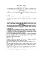
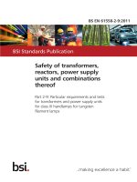
any of the fill when an impact tool, as illustrated in Figure 11.4.13.102, is dropped once
from a height of 0,60 m so that the tapered end of the tool strikes the bulb or capillary in a
perpendicular position. For this test, the capillary or the bulb shall be on a concrete surface.
Copyrighted material licensed to BR Demo by Thomson Reuters (Scientific), Inc., subscriptions.techstreet.com, downloaded on Nov-28-2014 by James Madison. No further reproduction or distribution is permitted. Uncontrolled when printe
– 14 –
– 15 –
If the capillary is provided with a separate shroud or sleeve, it is to be left in place during the test described
above.
(25,4 mm)
60
°
(25,4 mm)
R = 3,2 mm
L
IEC 564/2000
Material: Steel, CRS, Break all corners
L to be sized to obtain total mass of 0,454 kg
Figure 11.4.13.102 – Impact tool
Additional subclauses:
11.4.101
Type 2.N action
A Type 2.N action shall be so designed that in the event of a leak in the sensing element, or in
any other part between the sensing element and the switch head, the declared disconnection
or interruption is provided before the sum of the declared operating value and drift is exceeded.
Compliance is checked by the following test:
The operating value of a Type 2.N control is measured under the conditions of Clause 15
of Part 1. If the control has means for setting, it is set to the highest value.
After this measurement, a hole is artificially produced in the sensing element and the
measurement of the operating value is repeated.
No positive drift is allowed above the declared value.
The test can be replaced by theoretical computations of the physical mode of operation.
A separate shroud or sleeve may be employed for protection of the bulb and capillary to achieve conformance with
Clause 18.
In Canada and the USA, a Type 2.N action is checked by item c) of 11.4.13.102.
11.4.102
Type 2.P action
A Type 2.P action shall be so designed that it operates in its intended manner after a thermal
cycling test.
Compliance is checked by the test of 17.101.
11.4.103
Bimetallic single-operation device
A bimetallic single-operation device shall be so designed that it does not reset above the reset
value declared in Table 7.2, Item 103.
Copyrighted material licensed to BR Demo by Thomson Reuters (Scientific), Inc., subscriptions.techstreet.com, downloaded on Nov-28-2014 by James Madison. No further reproduction or distribution is permitted. Uncontrolled when printe
60730-2-9 IEC:2008+A1:2011
60730-2-9 IEC:2008+A1:2011
Compliance is checked by the test of 17.15.
11.4.104
Type 1.X or 2.X
A Type 1.X or 2.X action shall be so designed that a turn action can only be accomplished after
the completion of a push action or a pull action. Only rotation shall be required to return the
actuating member of the control to the off or rest position.
Compliance is checked by the tests of 18.101.
11.4.105
Type 1.Z or 2.Z
A Type 1.Z or 2.Z action shall be so designed that a turn action can only be accomplished after
the completion of a push action or a pull action.
Compliance is checked by the tests of 18.101.
11.4.106
Voltage maintained thermal cut-out
A voltage maintained thermal cut-out shall be so designed that it does not reset above the
reset value declared in Table 7.2, Item 111.
11.4.107
Type 1.AM or 2.AM
A Type 1.AM or 2.AM action shall be so designed that it operates in its intended manner after
the declared agricultural environmental exposures.
Compliance is checked by the tests of Annex DD.
11.6
Mounting of controls
11.6.3
Mounting of independently mounted controls
Additional subclause:
11.6.3.101 For agricultural thermostats declared in Table 7.2, Item 117, the mounting method
shall be such that the integrity of the protection by the enclosure is not compromised.
Additional subclause:
11.101
Time factor
If a time factor is declared, this shall be checked by one of the applicable determining methods
as indicated in Annex BB. The determined value shall not exceed the rated values.
See Table BB.1.
In Germany, for temperature sensing controls intended to control boiler water or flue gas temperature in heat
generating systems, the maximum values of time factor given in Table BB.1 shall not be exceeded.
12 Moisture and dust resistance
This clause of Part 1 is applicable except as follows:
Additional subclauses:
Copyrighted material licensed to BR Demo by Thomson Reuters (Scientific), Inc., subscriptions.techstreet.com, downloaded on Nov-28-2014 by James Madison. No further reproduction or distribution is permitted. Uncontrolled when printe
– 16 –
12.101
– 17 –
Refrigeration controls
Controls which have the switch head and sensing element mounted in the evaporator of
refrigeration or similar equipment, producing conditions of overtemperature and of freezing and
melting, shall maintain insulation integrity.
12.101.1
Compliance is checked by the following tests.
12.101.2 Controls which use a potting compound are given a softening test. Two samples are
heated in a heating chamber at 15 K above the maximum declared operating temperature for
16 h with the potting surface in the most unfavourable position. The potting material shall not
unduly soften or distort, crack or deteriorate.
12.101.3 The two samples used for the softening tests and one untested sample (three total)
are placed in water maintained at (90 ± 5) °C for 2 h. The three samples are then immediately
transferred to water at a temperature of below 5 °C and then frozen in a small, flexible
container at –35 °C for 2 h. Ten heating-freezing cycles are required.
In Canada and the USA, if the contact mechanism of defrost controls has the creepage distances and clearances
required for refrigeration controllers, one cycle only of heating and freezing is required, otherwise 10 cycles are
required.
12.101.4 Two consecutive heating-freezing cycles are performed in one working day, and
then 10 cycles are completed in five consecutive days, with the samples left in water at room
temperature for four overnight periods.
12.101.5 After the last freezing test, the samples are thawed to approximately room
temperature in water and the insulation resistance is measured from current-carrying parts to
grounded parts and to the surface of potting and/or insulating material; the direct current
voltmeter method is used. Insulation resistance shall be at least 50 000 Ω .
12.101.6 While the samples are still moist, a voltage equal to (2 × V R ) + 1 000 V is applied at
rated frequency for 1 min between current-carrying parts and grounded parts and the surface
of the potting and/or insulating material. No flashover or breakdown of insulation shall occur
during the test.
13 Electric strength and insulation resistance
This clause of Part 1 is applicable except as follows:
13.2
Electric strength
Addition:
In Canada and the USA, an independently mounted room thermostat for operation over 50 V, intended for
direct control of electric space-heating equipment, shall withstand for 1 min without breakdown, the application
of alternating potential of 900 V between the line and load terminals. A piece of insulating material may be
placed between the thermostat contacts during the test. There shall be no breakdown either through or across
the insulating material supporting the contact and terminal assemblies. This control shall be the control that is
designated as "SAMPLE 1" under the tests for compliance in 17.16.102.1 of this standard.
14 Heating
This clause of Part 1 is applicable except as follows:
14.4.3.1 The second paragraph is under consideration.
Addition:
Copyrighted material licensed to BR Demo by Thomson Reuters (Scientific), Inc., subscriptions.techstreet.com, downloaded on Nov-28-2014 by James Madison. No further reproduction or distribution is permitted. Uncontrolled when printe
60730-2-9 IEC:2008+A1:2011
60730-2-9 IEC:2008+A1:2011
For a voltage maintained thermal cut-out, the heating test of 14.4.3.1 is completed, after which
the temperature of the sensing element is raised until the contacts open. At this time, the
ambient temperature surrounding the sensing element is reduced to T max.1 in time period t 1 , at
a uniform rate. The test of 14.5.1 is then completed.
Table 14.1
Note 13) is under consideration.
Additional subclauses:
14.101
The following is applicable to controls classified under 6.7.101 to 6.7.103 inclusive.
14.101.1 As a means of complying with Note 12) of Table 14.1, if the temperature of
insulating parts exceeds that permitted in Table 14.1, then the test of 17.16.101 may be
conducted after the conditioning of 14.102 and 14.102.1.
14.102 A previously untested sample of the control is conditioned for 1 000 h in an oven
maintained at a temperature between 1,02 T 1 + 20 K and 1,05 times that temperature where T 1
is the maximum measured temperature on the insulating part during the test of Clause 14. The
control shall not be energized during this test.
14.102.1 If the elevated temperature is localized, such as at or near a terminal, the 1 000 h
conditioning is conducted with the control between T max and T max + 5 % for normal conditions,
but with the contacts closed and non-cycling. If necessary, the contacts may be forced closed
to provide the most arduous temperature conditions. A bimetal heater across the mains
is energized at 1,1 times rated voltage. A series bimetal heater shall conduct at 1,1 times rated
current.
15 Manufacturing deviation and drift
This clause of Part 1 is applicable except as follows:
15.1
Addition:
The values of manufacturing deviation and drift shall be according to Annex AA unless
otherwise declared by the manufacturer.
The explanatory matter is not applicable.
15.4
Addition:
Alternatively, the declared manufacturing deviation and drift may be expressed separately as a
tolerance value to the declared operating value.
15.5.3
Additional subclauses:
15.5.3.101 Controls intended for setting by the user shall be set at the maximum operating
temperature unless otherwise declared by the manufacturer.
15.5.3.102 Controls utilizing a bimetallic or similar sensing mechanism or that portion of a
control intended to be exposed to a controlled ambient shall be placed in a circulating air oven
to determine the operating value.
15.5.3.103 For bimetallic and similar type controls, the temperature shall be determined by
mounting a 0,25 mm thermocouple wire to the sensing portion of an identical control not
electrically connected and mounted adjacent to the control under test in a circulating air oven.
15.5.3.104 For fluid expansion type controls, a maximum 0,25 mm thermocouple shall be
attached to the sensing portion, using a suitable adhesive.
Copyrighted material licensed to BR Demo by Thomson Reuters (Scientific), Inc., subscriptions.techstreet.com, downloaded on Nov-28-2014 by James Madison. No further reproduction or distribution is permitted. Uncontrolled when printe
– 18 –