Iec 60747 14 5 2010
Bạn đang xem bản rút gọn của tài liệu. Xem và tải ngay bản đầy đủ của tài liệu tại đây (1.11 MB, 42 trang )
IEC 60747-14-5
®
Edition 1.0
2010-02
INTERNATIONAL
STANDARD
Semiconductor devices –
Part 14-5: Semiconductor sensors – PN-junction semiconductor temperature
sensor
IEC 60747-14-5:2010
Dispositifs à semiconducteurs –
Partie 14-5: Capteurs à semiconducteurs – Capteur de température à
semiconducteurs à jonction PN
LICENSED TO MECON LIMITED - RANCHI/BANGALORE,
FOR INTERNAL USE AT THIS LOCATION ONLY, SUPPLIED BY BOOK SUPPLY BUREAU.
NORME
INTERNATIONALE
THIS PUBLICATION IS COPYRIGHT PROTECTED
Copyright © 2010 IEC, Geneva, Switzerland
All rights reserved. Unless otherwise specified, no part of this publication may be reproduced or utilized in any form or by
any means, electronic or mechanical, including photocopying and microfilm, without permission in writing from either IEC or
IEC's member National Committee in the country of the requester.
If you have any questions about IEC copyright or have an enquiry about obtaining additional rights to this publication,
please contact the address below or your local IEC member National Committee for further information.
Droits de reproduction réservés. Sauf indication contraire, aucune partie de cette publication ne peut être reproduite
ni utilisée sous quelque forme que ce soit et par aucun procédé, électronique ou mécanique, y compris la photocopie
et les microfilms, sans l'accord écrit de la CEI ou du Comité national de la CEI du pays du demandeur.
Si vous avez des questions sur le copyright de la CEI ou si vous désirez obtenir des droits supplémentaires sur cette
publication, utilisez les coordonnées ci-après ou contactez le Comité national de la CEI de votre pays de résidence.
About the IEC
The International Electrotechnical Commission (IEC) is the leading global organization that prepares and publishes
International Standards for all electrical, electronic and related technologies.
About IEC publications
The technical content of IEC publications is kept under constant review by the IEC. Please make sure that you have the
latest edition, a corrigenda or an amendment might have been published.
Catalogue of IEC publications: www.iec.ch/searchpub
The IEC on-line Catalogue enables you to search by a variety of criteria (reference number, text, technical committee,…).
It also gives information on projects, withdrawn and replaced publications.
IEC Just Published: www.iec.ch/online_news/justpub
Stay up to date on all new IEC publications. Just Published details twice a month all new publications released. Available
on-line and also by email.
Electropedia: www.electropedia.org
The world's leading online dictionary of electronic and electrical terms containing more than 20 000 terms and definitions
in English and French, with equivalent terms in additional languages. Also known as the International Electrotechnical
Vocabulary online.
Customer Service Centre: www.iec.ch/webstore/custserv
If you wish to give us your feedback on this publication or need further assistance, please visit the Customer Service
Centre FAQ or contact us:
Email:
Tel.: +41 22 919 02 11
Fax: +41 22 919 03 00
A propos de la CEI
La Commission Electrotechnique Internationale (CEI) est la première organisation mondiale qui élabore et publie des
normes internationales pour tout ce qui a trait à l'électricité, à l'électronique et aux technologies apparentées.
A propos des publications CEI
Le contenu technique des publications de la CEI est constamment revu. Veuillez vous assurer que vous possédez
l’édition la plus récente, un corrigendum ou amendement peut avoir été publié.
Catalogue des publications de la CEI: www.iec.ch/searchpub/cur_fut-f.htm
Le Catalogue en-ligne de la CEI vous permet d’effectuer des recherches en utilisant différents critères (numéro de référence,
texte, comité d’études,…). Il donne aussi des informations sur les projets et les publications retirées ou remplacées.
Just Published CEI: www.iec.ch/online_news/justpub
Restez informé sur les nouvelles publications de la CEI. Just Published détaille deux fois par mois les nouvelles
publications parues. Disponible en-ligne et aussi par email.
Electropedia: www.electropedia.org
Le premier dictionnaire en ligne au monde de termes électroniques et électriques. Il contient plus de 20 000 termes et
dộfinitions en anglais et en franỗais, ainsi que les termes équivalents dans les langues additionnelles. Egalement appelé
Vocabulaire Electrotechnique International en ligne.
Service Clients: www.iec.ch/webstore/custserv/custserv_entry-f.htm
Si vous désirez nous donner des commentaires sur cette publication ou si vous avez des questions, visitez le FAQ du
Service clients ou contactez-nous:
Email:
Tél.: +41 22 919 02 11
Fax: +41 22 919 03 00
LICENSED TO MECON LIMITED - RANCHI/BANGALORE,
FOR INTERNAL USE AT THIS LOCATION ONLY, SUPPLIED BY BOOK SUPPLY BUREAU.
IEC Central Office
3, rue de Varembé
CH-1211 Geneva 20
Switzerland
Email:
Web: www.iec.ch
IEC 60747-14-5
®
Edition 1.0
2010-02
INTERNATIONAL
STANDARD
LICENSED TO MECON LIMITED - RANCHI/BANGALORE,
FOR INTERNAL USE AT THIS LOCATION ONLY, SUPPLIED BY BOOK SUPPLY BUREAU.
NORME
INTERNATIONALE
Semiconductor devices –
Part 14-5: Semiconductor sensors – PN-junction semiconductor temperature
sensor
Dispositifs à semiconducteurs –
Partie 14-5: Capteurs à semiconducteurs – Capteur de température à
semiconducteurs à jonction PN
INTERNATIONAL
ELECTROTECHNICAL
COMMISSION
COMMISSION
ELECTROTECHNIQUE
INTERNATIONALE
PRICE CODE
CODE PRIX
ICS 31.080.01
® Registered trademark of the International Electrotechnical Commission
Marque déposée de la Commission Electrotechnique Internationale
R
ISBN 2-8318-1078-8
–2–
60747-14-5 © IEC:2010
CONTENTS
FOREWORD...........................................................................................................................4
1
Scope ...............................................................................................................................6
2
Normative references .......................................................................................................6
3
Terms, definitions and symbols ........................................................................................6
4
3.1 Terms and definitions ..............................................................................................6
3.2 Symbols ..................................................................................................................7
Essential ratings and characteristics.................................................................................7
4.1
4.2
5.1
5.2
5.3
5.4
5.5
5.6
5.7
5.8
General ...................................................................................................................8
Circuit diagrams of PN-junction temperature sensors .............................................. 8
Temperature sensitivity ......................................................................................... 10
5.3.1 Purpose..................................................................................................... 10
5.3.2 Circuit diagram .......................................................................................... 11
5.3.3 Principle of measurement .......................................................................... 11
5.3.4 Measurement procedure ............................................................................ 11
5.3.5 Specified conditions .................................................................................. 12
Bias supply operating current ................................................................................ 12
5.4.1 Purpose..................................................................................................... 12
5.4.2 Circuit diagram .......................................................................................... 12
5.4.3 Measurement procedure ............................................................................ 12
5.4.4 Specified conditions .................................................................................. 12
Output voltage....................................................................................................... 12
5.5.1 Purpose..................................................................................................... 12
5.5.2 Circuit diagram .......................................................................................... 13
5.5.3 Measurement procedure ............................................................................ 13
5.5.4 Specified conditions .................................................................................. 13
Nonlinearity ........................................................................................................... 13
5.6.1 Purpose..................................................................................................... 13
5.6.2 Circuit diagram .......................................................................................... 13
5.6.3 Principle of measurement .......................................................................... 13
5.6.4 Measurement procedure ............................................................................ 14
5.6.5 Specified conditions .................................................................................. 14
Line regulation ...................................................................................................... 14
5.7.1 Purpose..................................................................................................... 14
5.7.2 Circuit diagram .......................................................................................... 14
5.7.3 Principle of measurement .......................................................................... 14
5.7.4 Measurement procedure ............................................................................ 15
5.7.5 Specified conditions .................................................................................. 15
Load regulation ..................................................................................................... 15
5.8.1 Purpose..................................................................................................... 15
5.8.2 Circuit diagram .......................................................................................... 15
LICENSED TO MECON LIMITED - RANCHI/BANGALORE,
FOR INTERNAL USE AT THIS LOCATION ONLY, SUPPLIED BY BOOK SUPPLY BUREAU.
5
General ...................................................................................................................7
Limiting values (absolute maximum rating system) ..................................................8
4.2.1 Electrical limiting values ..............................................................................8
4.2.2 Temperatures ..............................................................................................8
4.3 Electrical characteristics..........................................................................................8
Measuring methods ..........................................................................................................8
60747-14-5 © IEC:2010
–3–
5.8.3 Principle of measurement .......................................................................... 15
5.8.4 Measurement procedure ............................................................................ 16
5.8.5 Specified conditions .................................................................................. 16
5.9 Reliability test........................................................................................................ 16
5.9.1 Steady-state life ........................................................................................ 16
5.9.2 Temperature humidity life .......................................................................... 16
Annex A (informative) Features of a semiconductor temperature sensor ............................. 17
Bibliography.......................................................................................................................... 18
Figure 1 – The circuit diagram of a PN-junction temperature sensor with a negative
temperature coefficient ...........................................................................................................9
Figure 3 – Circuit diagram for the measurement of the temperature sensitivity...................... 11
Figure 4 – Circuit diagram for the measurement of the temperature sensitivity...................... 11
Figure 5 – Circuit diagram for the measurement of the bias supply operating current ............ 12
Figure 6 – Measurement principle of the nonlinearity ............................................................ 13
Figure 7 – Circuit diagram for the measurement of the line regulation ................................... 14
Table 1 – Electrical limiting values ..........................................................................................8
Table 2 – Parameters electrical characteristics .......................................................................8
Table A.1 – Features of some examples of semiconductor temperature sensors ................... 17
LICENSED TO MECON LIMITED - RANCHI/BANGALORE,
FOR INTERNAL USE AT THIS LOCATION ONLY, SUPPLIED BY BOOK SUPPLY BUREAU.
Figure 2 – The circuit diagram of a PN-junction temperature sensor with a positive
temperature coefficient ......................................................................................................... 10
60747-14-5 © IEC:2010
–4–
INTERNATIONAL ELECTROTECHNICAL COMMISSION
____________
SEMICONDUCTOR DEVICES –
Part 14-5: Semiconductor sensors –
PN-junction semiconductor temperature sensor
FOREWORD
2) The formal decisions or agreements of IEC on technical matters express, as nearly as possible, an international
consensus of opinion on the relevant subjects since each technical committee has representation from all
interested IEC National Committees.
3) IEC Publications have the form of recommendations for international use and are accepted by IEC National
Committees in that sense. While all reasonable efforts are made to ensure that the technical content of IEC
Publications is accurate, IEC cannot be held responsible for the way in which they are used or for any
misinterpretation by any end user.
4) In order to promote international uniformity, IEC National Committees undertake to apply IEC Publications
transparently to the maximum extent possible in their national and regional publications. Any divergence
between any IEC Publication and the corresponding national or regional publication shall be clearly indicated in
the latter.
5) IEC itself does not provide any attestation of conformity. Independent certification bodies provide conformity
assessment services and, in some areas, access to IEC marks of conformity. IEC is not responsible for any
services carried out by independent certification bodies.
6) All users should ensure that they have the latest edition of this publication.
7) No liability shall attach to IEC or its directors, employees, servants or agents including individual experts and
members of its technical committees and IEC National Committees for any personal injury, property damage or
other damage of any nature whatsoever, whether direct or indirect, or for costs (including legal fees) and
expenses arising out of the publication, use of, or reliance upon, this IEC Publication or any other IEC
Publications.
8) Attention is drawn to the Normative references cited in this publication. Use of the referenced publications is
indispensable for the correct application of this publication.
9) Attention is drawn to the possibility that some of the elements of this IEC Publication may be the subject of
patent rights. IEC shall not be held responsible for identifying any or all such patent rights.
International Standard IEC 60747-14-5 has been prepared by subcommittee 47E: Discrete
semiconductor devices, of IEC technical committee 47: Semiconductor devices.
The text of this standard is based on the following documents:
FDIS
Report on voting
47E/390/FDIS
47E/392/RVD
Full information on the voting for the approval of this standard can be found in the report on
voting indicated in the above table.
This publication has been drafted in accordance with the ISO/IEC Directives, Part 2.
A list of all the parts in the IEC 60747 series, under the general title Semiconductor devices –
Discrete devices, can be found on the IEC website.
LICENSED TO MECON LIMITED - RANCHI/BANGALORE,
FOR INTERNAL USE AT THIS LOCATION ONLY, SUPPLIED BY BOOK SUPPLY BUREAU.
1) The International Electrotechnical Commission (IEC) is a worldwide organization for standardization comprising
all national electrotechnical committees (IEC National Committees). The object of IEC is to promote
international co-operation on all questions concerning standardization in the electrical and electronic fields. To
this end and in addition to other activities, IEC publishes International Standards, Technical Specifications,
Technical Reports, Publicly Available Specifications (PAS) and Guides (hereafter referred to as “IEC
Publication(s)”). Their preparation is entrusted to technical committees; any IEC National Committee interested
in the subject dealt with may participate in this preparatory work. International, governmental and nongovernmental organizations liaising with the IEC also participate in this preparation. IEC collaborates closely
with the International Organization for Standardization (ISO) in accordance with conditions determined by
agreement between the two organizations.
60747-14-5 © IEC:2010
–5–
The committee has decided that the contents of this publication will remain unchanged until
the stability date indicated on the IEC web site under "" in the data
related to the specific publication. At this date, the publication will be
•
•
•
•
reconfirmed,
withdrawn,
replaced by a revised edition, or
amended.
LICENSED TO MECON LIMITED - RANCHI/BANGALORE,
FOR INTERNAL USE AT THIS LOCATION ONLY, SUPPLIED BY BOOK SUPPLY BUREAU.
–6–
60747-14-5 © IEC:2010
SEMICONDUCTOR DEVICES –
Part 14-5: Semiconductor sensors –
PN-junction semiconductor temperature sensor
1
Scope
2
Normative references
The following referenced documents are indispensable for the application of this document.
For dated references, only the edition cited applies. For undated references, the latest edition
of the referenced document (including any amendments) applies.
IEC 60747-14-1, Semiconductor devices – Part 14-1: Semiconductor sensors – General and
classification
IEC 60749-5, Semiconductor devices – Mechanical and climatic test methods – Part 5:
Steady-state temperature humidity bias life test
IEC 60749-6, Semiconductor devices – Mechanical and climatic test methods – Part 6:
Storage at high temperature
3
3.1
Terms, definitions and symbols
Terms and definitions
For the purpose of this document, the following terms and definitions apply. For the general
terms and definitions, refer to IEC 60747-14-1.
3.1.1
voltage output style
output style of the temperature sensor where output change is expressed by voltage change
3.1.2
current output style
output style of the temperature sensor where output change is expressed by current change
3.1.3
supply voltage range
voltage range where the sensor operates normally
3.1.4
operating temperature range
temperature range where the sensor operates normally
LICENSED TO MECON LIMITED - RANCHI/BANGALORE,
FOR INTERNAL USE AT THIS LOCATION ONLY, SUPPLIED BY BOOK SUPPLY BUREAU.
This standard is applicable to semiconductor PN-junction temperature sensors and defines
terms, definitions, symbols, essential ratings, characteristics and test methods that can be
used to determine the characteristics of semiconductor types of PN-junction temperature
sensors.
60747-14-5 © IEC:2010
–7–
3.1.5
line regulation
ratio of output voltage change to supply voltage change
NOTE
The unit mV/V is usually used in the line regulation.
3.1.6
load regulation
ratio of output voltage change to output current change
NOTE
The unit mV/mA is usually used in the load regulation.
3.2
Symbols
sensitivity
S
ΔF
full scale of temperature change
H
hysteresis
H max
maximum difference between two outputs by the increasing input and decreasing input
Rx
resistors
Qx
transistors
R max
maximum difference between or among outputs
I1
current at emitter of transistor Q 1
current at emitter of transistor Q 2
I2
V BE2
voltage between base and emitter of transistor Q 1
voltage between base and emitter of transistor Q 2
VT
equals
k
Boltzmann constant
T
absolute temperature
q
electron charge
Sj
junction area
VF
junction voltage
IF
forward current
Na
acceptor density
Nd
donor density
Dp
hole diffusion constant
Dn
electron diffusion constant
Lp
hole diffusion distance
Ln
electron diffusion distance
ni
intrinsic carrier density
V BE1
4
4.1
kT
q
Essential ratings and characteristics
General
This clause gives ratings and characteristics required for specifying PN-junction temperature
sensors.
LICENSED TO MECON LIMITED - RANCHI/BANGALORE,
FOR INTERNAL USE AT THIS LOCATION ONLY, SUPPLIED BY BOOK SUPPLY BUREAU.
ΔV out full scale of output voltage change
60747-14-5 © IEC:2010
–8–
4.2
Limiting values (absolute maximum rating system)
4.2.1
Electrical limiting values
Limiting values shall be specified as in Table 1.
Table 1 – Electrical limiting values
4.2.2
Subclause
Parameters
Min.
Max.
4.2.1.1
Bias supply voltage
+
4.2.1.2
Output terminal voltage
+
Temperatures
Storage temperature
4.3
Electrical characteristics
The characteristics shall apply over the full operating temperature range, unless otherwise
specified.
The parameters shall be specified as in Table 2.
Table 2 – Parameters electrical characteristics
Subclause
5
5.1
Parameters
Min.
Typical
Max.
+
+
+
+
+
+
+
4.3.1
Temperature sensitivity
4.3.2
Bias supply operating current
4.3.3
Output voltage
4.3.4
Nonlinearity
4.3.5
Line regulation
+
4.3.6
Load regulation
+
+
+
Measuring methods
General
This clause prescribes measuring methods for electrical characteristics of PN-junction
temperature sensors.
5.2
Circuit diagrams of PN-junction temperature sensors
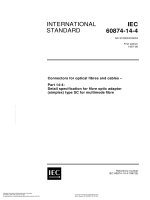
Circuit diagrams of PN-junction temperature sensors are shown as follows. Figure 1 is a
typical circuit diagrams of a PN-junction temperature sensor with a negative temperature
coefficient.
LICENSED TO MECON LIMITED - RANCHI/BANGALORE,
FOR INTERNAL USE AT THIS LOCATION ONLY, SUPPLIED BY BOOK SUPPLY BUREAU.
Operating temperature
60747-14-5 © IEC:2010
–9–
IF
IF
IF
Vout
VF3
Q3
VF2
VF1
Q1
IEC
101/10
Figure 1 – The circuit diagram of a PN-junction temperature sensor
with a negative temperature coefficient
⎛ Dp
Dn
IF = S jq ⋅ ⎜
+
⎜ Lp N d Ln N a
⎝
⎞
⎟ ⋅ n 2 ⋅ exp ⎛⎜ qVF ⎞⎟
⎟ i
⎝ kT ⎠
⎠
(1)
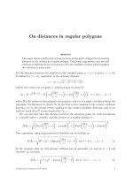
Figure 2 shows typical circuit diagrams of a PN-junction temperature sensor with a positive
temperature coefficient.
LICENSED TO MECON LIMITED - RANCHI/BANGALORE,
FOR INTERNAL USE AT THIS LOCATION ONLY, SUPPLIED BY BOOK SUPPLY BUREAU.
Q2
60747-14-5 © IEC:2010
– 10 –
I
I
IPTAT
Q1
Q2
xM
x1
VF1
Vout
ΔVF
R1
R2
2I
IEC 102/10
M
emitter size ratio of Q 1 and Q 2
Figure 2 – The circuit diagram of a PN-junction temperature sensor
with a positive temperature coefficient
ΔVF = VF1 − VF2
=
kT
ln(M )
q
(2)
ΔVF
R1
(3)
I PTAT =
⎛
R ⎞
Vout = ⎜⎜1 + 2 ⎟⎟ΔVF − VF1
R1 ⎠
⎝
⎛
R ⎞ kT
= ⎜⎜1 + 2 ⎟⎟
ln( M ) − VF1
R1 ⎠ q
⎝
5.3
5.3.1
Temperature sensitivity
Purpose
To measure the temperature sensitivity under specified conditions.
(4)
LICENSED TO MECON LIMITED - RANCHI/BANGALORE,
FOR INTERNAL USE AT THIS LOCATION ONLY, SUPPLIED BY BOOK SUPPLY BUREAU.
VF2
60747-14-5 © IEC:2010
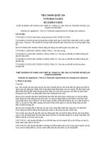
5.3.2
– 11 –
Circuit diagram
PNJ temp
VDD
sensor
VOUT
VSS
V2
V1
IEC
103/10
Figure 3 – Circuit diagram for the measurement of the temperature sensitivity
Principle of measurement
Temperature sensitivity α SE is derived from the output voltages at low measuring temperature
T L and high measuring temperature T H as follows:
α SE =
VoutH − VoutL
TH − TL
(5)
where
V outL
is the output voltage at high measuring temperature T H ;
is the output voltage at low measuring temperature T L ;
αSE
is expressed with the unit mV/ ° C. See Figure 4.
V outH
Output voltage (Vout)
VoutL(Ta = TL)
αSE
VoutH(Ta = TH)
0
TL
Temperature
TH
Ta (°C)
IEC
104/10
Figure 4 – Circuit diagram for the measurement of the temperature sensitivity
5.3.4
Measurement procedure
The supply voltage shall be applied as specified.
LICENSED TO MECON LIMITED - RANCHI/BANGALORE,
FOR INTERNAL USE AT THIS LOCATION ONLY, SUPPLIED BY BOOK SUPPLY BUREAU.
5.3.3
60747-14-5 © IEC:2010
– 12 –
Ambient or reference-point temperature of the sensor shall be set at the specified low
measuring temperature.
The output voltage at low measuring temperature, V outL, is measured using voltmeter V 2 .
The ambient or reference-point temperature of the sensor shall be set at the specified high
measuring temperature.
The output voltage at high measuring temperature, V outH, is measured using voltmeter V 2 .
The temperature sensitivity is calculated from Equation (5).
5.3.5
Specified conditions
Supply voltage
–
Low measuring temperature
–
High measuring temperature
5.4
Bias supply operating current
5.4.1
Purpose
To measure the bias supply operating current under specified conditions.
5.4.2
Circuit diagram
PNJ temp
VDD
A
VOUT
sensor
VSS
V
IEC
105/10
Figure 5 – Circuit diagram for the measurement of the bias supply operating current
NOTE
5.4.3
V OUT is usually open.
Measurement procedure
The ambient or reference-point temperature of the sensor shall be set at the specified value.
The supply voltage shall be applied as specified.
The bias supply operating current is measured using the amperemeter A.
5.4.4
Specified conditions
–
Ambient or reference-point temperature
–
Supply voltage
5.5
5.5.1
Output voltage
Purpose
To measure the output voltage under specified conditions.
LICENSED TO MECON LIMITED - RANCHI/BANGALORE,
FOR INTERNAL USE AT THIS LOCATION ONLY, SUPPLIED BY BOOK SUPPLY BUREAU.
–
60747-14-5 © IEC:2010
5.5.2
– 13 –
Circuit diagram
The circuit diagram for the measurement of the output voltage is the same as the diagram
shown in Figure 3.
5.5.3
Measurement procedure
Ambient or reference-point temperature of the sensor shall be set at the specified value.
The supply voltage shall be applied as specified.
The output voltage is measured using voltmeter V 2 .
5.5.4
Specified conditions
Ambient or reference-point temperature
–
Supply voltage
5.6
5.6.1
Nonlinearity
Purpose
To measure the nonlinearity under specified conditions.
5.6.2
Circuit diagram
The circuit diagram for the measurement of the nonlinearity is the same as the diagram shown
in Figure 3.
5.6.3
Principle of measurement
Output voltage
VOUT (V)
a
VOUT (Ta = X)
a
(B) Measured value
b
a
(A) Approximate line
VOUT (Ta = Y)
X
0
Temperature
Y
Ta (°C)
IEC
106/10
Figure 6 – Measurement principle of the nonlinearity
Figure 6 shows the measurement principle of the nonlinearity.
Measurements are carried out at the temperatures between the lowest measurement
temperature X and the highest measurement temperature Y with the temperature step ΔT .
Next, the approximate straight line is plotted. The difference a between the measured value
LICENSED TO MECON LIMITED - RANCHI/BANGALORE,
FOR INTERNAL USE AT THIS LOCATION ONLY, SUPPLIED BY BOOK SUPPLY BUREAU.
–
60747-14-5 © IEC:2010
– 14 –
and the approximate line is calculated at each measurement temperature. The approximate
line should be plotted for the maximum difference a max to be smallest. Nonlinearity α NL is
given by the equation
α NL = amax / b
(6)
where b is the difference between the output voltage at the lowest measurement temperature
and that at the highest measuring temperature. The unit of α NL is percent.
5.6.4
Measurement procedure
The supply voltage shall be applied as specified.
The output voltages are measured using voltmeter V 2 at each measurement temperature.
Nonlinearity is calculated using Equation (6).
5.6.5
Specified conditions
Lowest measurement temperature
Highest measurement temperature
Measurement temperature step
Supply voltage
5.7
5.7.1
Line regulation
Purpose
To measure the line regulation under specified conditions.
5.7.2
Circuit diagram
The circuit diagram for the measurement of the line regulation is shown in Figure 7.
VDD
PNJ temp
VOUT
A
sensor
VSS
V1
IOUT
V2
IEC
107/10
Figure 7 – Circuit diagram for the measurement of the line regulation
5.7.3
Principle of measurement
The line regulation αLR is the input voltage dependence of the output voltage. It is given as
follows:
LICENSED TO MECON LIMITED - RANCHI/BANGALORE,
FOR INTERNAL USE AT THIS LOCATION ONLY, SUPPLIED BY BOOK SUPPLY BUREAU.
The ambient or reference-point temperature of the sensor shall be set from the specified
lowest measurement temperature to the specified highest measurement temperature by the
specified measurement temperature step.
60747-14-5 © IEC:2010
– 15 –
αLR = ΔVOUT / ΔVSUP
(7)
where ΔVOUT is the output voltage difference between the specified maximum supply voltage
and the specified minimum supply voltage under the specified output current, and ΔVSUP is
the difference of the specified maximum supply voltage and the specified minimum one. The
unit mV/V is usually used in the line regulation.
5.7.4
Measurement procedure
The ambient or reference-point temperature of the sensor shall be set at the specified value.
The maximum supply voltage shall be applied as specified.
The minimum supply voltage shall be applied as specified.
The output voltage is measured using voltmeter V 2 under specified output current.
The line regulation is calculated using Equation (7).
5.7.5
Specified conditions
Ambient or reference-point temperature
Maximum supply voltage
Minimum supply voltage
Output current
5.8
5.8.1
Load regulation
Purpose
To measure the load regulation under specified conditions.
5.8.2
Circuit diagram
The circuit diagram for the measurement of the load regulation is the same as the diagram
shown in Figure 7.
5.8.3
Principle of measurement
The load regulation αLOR is the output current dependence of the output voltage. It is given
as follows:
αLOR = ΔVOUT / ΔIOUT
(8)
where ΔVOUT is the output voltage difference between the specified maximum output current
and the specified minimum output current under the specified input voltage, and ΔI OUT is the
difference of the specified maximum output current and the specified minimum one. Usually
the specific minimum current is set to zero, that is no load condition. The unit mV/mA is
usually used in the load regulation.
LICENSED TO MECON LIMITED - RANCHI/BANGALORE,
FOR INTERNAL USE AT THIS LOCATION ONLY, SUPPLIED BY BOOK SUPPLY BUREAU.
The output voltage is measured using voltmeter V 2 under specified output current.
– 16 –
5.8.4
60747-14-5 © IEC:2010
Measurement procedure
The ambient or reference-point temperature of the sensor shall be set at the specified value.
The supply voltage shall be applied as specified.
The output voltage is measured using voltmeter V 2 under the specified maximum output
current.
The output voltage is measured using voltmeter V 2 under no load condition.
The load regulation is calculated using Equation (8).
Specified conditions
Ambient or reference-point temperature
Supply voltage
Maximum output current
5.9
Reliability test
5.9.1
Steady-state life
IEC 60749-6 is applicable with some change for this procedure, unless otherwise stated in the
relevant specifications.
The principle test conditions in this standard are as follows:
a) ambient temperature to be the maximum operating ambient temperature in the ratings
of the devices;
b) application of the nominal or maximum supply voltage in the ratings of the device;
c) no temperature along the input axis of the device.
5.9.2
Temperature humidity life
IEC 60749-5 is applicable for the test procedure, unless otherwise stated in the relevant
specifications.
The principle test conditions in this standard are as follows:
a) application of the nominal or maximum supply voltage in the ratings of the device;
b) no temperature along the input axis of the device.
LICENSED TO MECON LIMITED - RANCHI/BANGALORE,
FOR INTERNAL USE AT THIS LOCATION ONLY, SUPPLIED BY BOOK SUPPLY BUREAU.
5.8.5
60747-14-5 © IEC:2010
– 17 –
Annex A
(informative)
Features of a semiconductor temperature sensor
Table A.1 shows an example of the overall features of a semiconductor temperature sensor.
Table A.1 – Features of some examples of semiconductor temperature sensors
Type of
example
Supply
voltage
Source
current
Operating
temperature
range
Accuracy
Temperature
coefficient
(W×H×D)
μA
°C
°C
mV/°C
mm
Size
4,0 - 30,0
60,0
0 - 100
±1,0
10,0
4,95×5,05×3,92
B
2,7 - 5,5
30,0
–55 - 125
±0,5
10,0
2,60×0,90×1,50
C
2,4 - 6,0
4,5
–40 - 100
±2,5
–8,5
2,10×1,10×2,00
D
2,7 - 5,5
0,5
–40 - 150
±1,0
20,0
5,80×1,35×4,80
E
2,4 - 10,0
30,0
–40 - 100
±3,0
20,0
0,80×0,80×1,60
F
3,0 - 11,0
30,0
–40 - 125
±1,0
25,0
1,20×0,80×1,40
G
5,0
1,5
–40 - 85
±0,5
20,0
52,00×24,00×36,00
LICENSED TO MECON LIMITED - RANCHI/BANGALORE,
FOR INTERNAL USE AT THIS LOCATION ONLY, SUPPLIED BY BOOK SUPPLY BUREAU.
A
– 18 –
60747-14-5 © IEC:2010
Bibliography
IEC 60721-3-0:1984, Classification of environmental conditions – Part 3: Classification of
groups of environmental parameters and their severities – Introduction
Amendment (1987)
IEC 60721-3-1:1997, Classification of environmental conditions – Part 3 Classification of
groups of environmental parameters and their severities – Section 1: Storage
IEC 60747-1:2006, Semiconductor devices – Part 1: General
IEC 60749-1:2002, Semiconductor devices – Mechanical and climatic test methods – Part 1:
General
___________
LICENSED TO MECON LIMITED - RANCHI/BANGALORE,
FOR INTERNAL USE AT THIS LOCATION ONLY, SUPPLIED BY BOOK SUPPLY BUREAU.
IEC 60749-36:2003, Semiconductor devices – Mechanical and climatic test methods – Part 36:
Acceleration, steady state
LICENSED TO MECON LIMITED - RANCHI/BANGALORE,
FOR INTERNAL USE AT THIS LOCATION ONLY, SUPPLIED BY BOOK SUPPLY BUREAU.
– 20 –
60747-14-5 © CEI:2010
SOMMAIRE
AVANT-PROPOS .................................................................................................................. 22
1
Domaine d'application .................................................................................................... 24
2
Références normatives ................................................................................................... 24
3
Termes, définitions et symboles ..................................................................................... 24
4
3.1 Termes et définitions ............................................................................................. 24
3.2 Symboles .............................................................................................................. 25
Valeurs limites et caractéristiques essentielles ............................................................... 26
4.1
4.2
5.1
5.2
5.3
5.4
5.5
5.6
5.7
5.8
Généralités............................................................................................................ 26
Schémas de circuits de capteurs de température à jonction PN ............................. 27
Sensibilité à la température ................................................................................... 28
5.3.1 Objet ......................................................................................................... 28
5.3.2 Schéma de circuit ...................................................................................... 29
5.3.3 Principe de mesure.................................................................................... 29
5.3.4 Procédure de mesure ................................................................................ 30
5.3.5 Conditions spécifiées................................................................................. 30
Courant de fonctionnement d’alimentation de polarisation ..................................... 30
5.4.1 Objet ......................................................................................................... 30
5.4.2 Schéma de circuit ...................................................................................... 30
5.4.3 Procédure de mesure ................................................................................ 30
5.4.4 Conditions spécifiées................................................................................. 31
Tension de sortie................................................................................................... 31
5.5.1 Objet ......................................................................................................... 31
5.5.2 Schéma de circuit ...................................................................................... 31
5.5.3 Procédure de mesure ................................................................................ 31
5.5.4 Conditions spécifiées................................................................................. 31
Non-linéarité ......................................................................................................... 31
5.6.1 Objet ......................................................................................................... 31
5.6.2 Schéma de circuit ...................................................................................... 31
5.6.3 Principe de mesure.................................................................................... 32
5.6.4 Procédure de mesure ................................................................................ 32
5.6.5 Conditions spécifiées................................................................................. 32
Régulation de ligne ............................................................................................... 33
5.7.1 Objet ......................................................................................................... 33
5.7.2 Schéma de circuit ...................................................................................... 33
5.7.3 Principe de mesure.................................................................................... 33
5.7.4 Procédure de mesure ................................................................................ 33
5.7.5 Conditions spécifiées................................................................................. 33
Régulation de charge ............................................................................................ 34
5.8.1 Objet ......................................................................................................... 34
5.8.2 Schéma de circuit ...................................................................................... 34
LICENSED TO MECON LIMITED - RANCHI/BANGALORE,
FOR INTERNAL USE AT THIS LOCATION ONLY, SUPPLIED BY BOOK SUPPLY BUREAU.
5
Généralités............................................................................................................ 26
Valeurs limites (système des valeurs limites absolues).......................................... 26
4.2.1 Valeurs limites électriques ......................................................................... 26
4.2.2 Températures ............................................................................................ 26
4.3 Caractéristiques électriques .................................................................................. 26
Méthodes de mesure ...................................................................................................... 26
60747-14-5 © CEI:2010
– 21 –
5.8.3 Principe de mesure.................................................................................... 34
5.8.4 Procédure de mesure ................................................................................ 34
5.8.5 Conditions spécifiées................................................................................. 34
5.9 Essai de fiabilité .................................................................................................... 34
5.9.1 Vie en régime permanent........................................................................... 34
5.9.2 Durée de vie sous température et humidité ................................................ 35
Annexe A (informative) Caractéristiques d’un capteur de température à semiconducteurs ... 36
Bibliographie......................................................................................................................... 37
Figure 1 – Schéma de circuit d’un capteur de température à jonction PN avec un
coefficient de température négatif ......................................................................................... 27
Figure 3 – Schéma de circuit pour la mesure de la sensibilité à la température..................... 29
Figure 4 – Schéma de circuit pour la mesure de la sensibilité à la température .................... 29
Figure 5 – Schéma de circuit pour la mesure du courant de fonctionnement
d’alimentation de polarisation ............................................................................................... 30
Figure 6 – Principe de mesure de la non-linéarité ................................................................. 32
Figure 7 – Schéma de mesure de la régulation de ligne ........................................................ 33
Tableau 1 – Valeurs limites électriques ................................................................................. 26
Tableau 2 – Paramètres des caractéristiques électriques...................................................... 26
Tableau A.1 − Caractéristiques d’exemples de capteurs de température à
semiconducteurs................................................................................................................... 36
LICENSED TO MECON LIMITED - RANCHI/BANGALORE,
FOR INTERNAL USE AT THIS LOCATION ONLY, SUPPLIED BY BOOK SUPPLY BUREAU.
Figure 2 – Schéma de circuit d’un capteur de température à jonction PN avec un
coefficient de température positif .......................................................................................... 28
60747-14-5 © CEI:2010
– 22 –
COMMISSION ÉLECTROTECHNIQUE INTERNATIONALE
____________
DISPOSITIFS À SEMICONDUCTEURS –
Partie 14-5: Capteurs à semiconducteurs –
Capteur de température à semiconducteurs à jonction PN
AVANT-PROPOS
2) Les décisions ou accords officiels de la CEI concernant les questions techniques représentent, dans la mesure
du possible, un accord international sur les sujets étudiés, étant donné que les Comités nationaux de la CEI
intéressés sont représentés dans chaque comité d’études.
3) Les Publications de la CEI se présentent sous la forme de recommandations internationales et sont agréées
comme telles par les Comités nationaux de la CEI. Tous les efforts raisonnables sont entrepris afin que la CEI
s'assure de l'exactitude du contenu technique de ses publications; la CEI ne peut pas être tenue responsable
de l'éventuelle mauvaise utilisation ou interprétation qui en est faite par un quelconque utilisateur final.
4) Dans le but d'encourager l'uniformité internationale, les Comités nationaux de la CEI s'engagent, dans toute la
mesure possible, appliquer de faỗon transparente les Publications de la CEI dans leurs publications
nationales et régionales. Toutes divergences entre toutes Publications de la CEI et toutes publications
nationales ou régionales correspondantes doivent être indiquées en termes clairs dans ces dernières.
5) La CEI elle-même ne fournit aucune attestation de conformité. Des organismes de certification indépendants
fournissent des services d'évaluation de conformité et, dans certains secteurs, accèdent aux marques de
conformité de la CEI. La CEI n'est responsable d'aucun des services effectués par les organismes de
certification indépendants.
6) Tous les utilisateurs doivent s'assurer qu'ils sont en possession de la dernière édition de cette publication.
7) Aucune responsabilité ne doit être imputée à la CEI, à ses administrateurs, employés, auxiliaires ou
mandataires, y compris ses experts particuliers et les membres de ses comités d'études et des Comités
nationaux de la CEI, pour tout préjudice causé en cas de dommages corporels et matériels, ou de tout autre
dommage de quelque nature que ce soit, directe ou indirecte, ou pour supporter les coûts (y compris les frais
de justice) et les dépenses découlant de la publication ou de l'utilisation de cette Publication de la CEI ou de
toute autre Publication de la CEI, ou au crédit qui lui est accordé.
8) L'attention est attirée sur les références normatives citées dans cette publication. L'utilisation de publications
référencées est obligatoire pour une application correcte de la présente publication.
9) L’attention est attirée sur le fait que certains des éléments de la présente Publication de la CEI peuvent faire
l’objet de droits de propriété intellectuelle ou de droits analogues. La CEI ne saurait être tenue pour
responsable de ne pas avoir identifié de tels droits de propriété et de ne pas avoir signalé leur existence.
La Norme internationale CEI 60747-14-5 a été établie par le sous-comité 47E: Dispositifs
discrets à semiconducteurs, du comité d'études 47 de la CEI: Dispositifs à semiconducteurs.
Le texte de cette norme est issu des documents suivants:
FDIS
Rapport de vote
47E/390/FDIS
47E/392/RVD
Le rapport de vote indiqué dans le tableau ci-dessus donne toute information sur le vote ayant
abouti à l'approbation de cette norme.
Cette publication a été rédigée selon les Directives ISO/CEI, Partie 2.
LICENSED TO MECON LIMITED - RANCHI/BANGALORE,
FOR INTERNAL USE AT THIS LOCATION ONLY, SUPPLIED BY BOOK SUPPLY BUREAU.
1) La Commission Electrotechnique Internationale (CEI) est une organisation mondiale de normalisation
composée de l'ensemble des comités électrotechniques nationaux (Comités nationaux de la CEI). La CEI a
pour objet de favoriser la coopération internationale pour toutes les questions de normalisation dans les
domaines de l'électricité et de l'électronique. A cet effet, la CEI – entre autres activités – publie des Normes
internationales, des Spécifications techniques, des Rapports techniques, des Spécifications accessibles au
public (PAS) et des Guides (ci-après dénommés "Publication(s) de la CEI"). Leur élaboration est confiée à des
comités d'études, aux travaux desquels tout Comité national intéressé par le sujet traité peut participer. Les
organisations internationales, gouvernementales et non gouvernementales, en liaison avec la CEI, participent
également aux travaux. La CEI collabore étroitement avec l'Organisation Internationale de Normalisation (ISO),
selon des conditions fixées par accord entre les deux organisations.
60747-14-5 © CEI:2010
– 23 –
Une liste de toutes les parties de la série CEI 60747, sous le titre général Dispositifs à
semiconducteurs – Dispositifs discrets, peut être consultée sur le site web de la CEI.
Le comité a décidé que le contenu de cette publication ne sera pas modifié avant la date de
stabilité indiquée sur le site web de la CEI sous "" dans les données
relatives à la publication recherchée. A cette date, la publication sera
•
•
•
•
reconduite,
supprimée,
remplacée par une édition révisée, ou
amendée.
LICENSED TO MECON LIMITED - RANCHI/BANGALORE,
FOR INTERNAL USE AT THIS LOCATION ONLY, SUPPLIED BY BOOK SUPPLY BUREAU.