Iec 61290 7 1 2007
Bạn đang xem bản rút gọn của tài liệu. Xem và tải ngay bản đầy đủ của tài liệu tại đây (228.97 KB, 24 trang )
INTERNATIONAL
STANDARD
NORME
INTERNATIONALE
IEC
CEI
61290-7-1
Second edition
Deuxième édition
2007-04
Part 7-1:
Out-of-band insertion losses –
Filtered optical power meter method
Amplificateurs optiques –
Méthodes d’essai –
Partie 7-1:
Pertes d’insertion hors-bande –
Méthode par puissance-mètre optique filtré
Reference number
Numéro de référence
IEC/CEI 61290-7-1:2007
LICENSED TO MECON Limited. - RANCHI/BANGALORE
FOR INTERNAL USE AT THIS LOCATION ONLY, SUPPLIED BY BOOK SUPPLY BUREAU.
Optical amplifiers –
Test methods –
THIS PUBLICATION IS COPYRIGHT PROTECTED
Copyright © 2007 IEC, Geneva, Switzerland
All rights reserved. Unless otherwise specified, no part of this publication may be reproduced or utilized in any form
or by any means, electronic or mechanical, including photocopying and microfilm, without permission in writing from
either IEC or IEC's member National Committee in the country of the requester.
If you have any questions about IEC copyright or have an enquiry about obtaining additional rights to this publication,
please contact the address below or your local IEC member National Committee for further information.
Droits de reproduction réservés. Sauf indication contraire, aucune partie de cette publication ne peut être reproduite
ni utilisée sous quelque forme que ce soit et par aucun procédé, électronique ou mécanique, y compris la photocopie
et les microfilms, sans l'accord écrit de la CEI ou du Comité national de la CEI du pays du demandeur.
Si vous avez des questions sur le copyright de la CEI ou si vous désirez obtenir des droits supplémentaires sur cette
publication, utilisez les coordonnées ci-après ou contactez le Comité national de la CEI de votre pays de résidence.
About the IEC
The International Electrotechnical Commission (IEC) is the leading global organization that prepares and publishes
International Standards for all electrical, electronic and related technologies.
About IEC publications
The technical content of IEC publications is kept under constant review by the IEC. Please make sure that you have the
latest edition, a corrigenda or an amendment might have been published.
Catalogue of IEC publications: www.iec.ch/searchpub
The IEC on-line Catalogue enables you to search by a variety of criteria (reference number, text, technical committee,…).
It also gives information on projects, withdrawn and replaced publications.
IEC Just Published: www.iec.ch/online_news/justpub
Stay up to date on all new IEC publications. Just Published details twice a month all new publications released. Available
on-line and also by email.
Customer Service Centre: www.iec.ch/webstore/custserv
If you wish to give us your feedback on this publication or need further assistance, please visit the Customer Service
Centre FAQ or contact us:
Email:
Tel.: +41 22 919 02 11
Fax: +41 22 919 03 00
A propos de la CEI
La Commission Electrotechnique Internationale (CEI) est la première organisation mondiale qui élabore et publie des
normes internationales pour tout ce qui a trait à l'électricité, à l'électronique et aux technologies apparentées.
A propos des publications CEI
Le contenu technique des publications de la CEI est constamment revu. Veuillez vous assurer que vous possédez
l’édition la plus récente, un corrigendum ou amendement peut avoir été publié.
Catalogue des publications de la CEI: www.iec.ch/searchpub/cur_fut-f.htm
Le Catalogue en-ligne de la CEI vous permet d’effectuer des recherches en utilisant différents critères (numéro de
référence, texte, comité d’études,…). Il donne aussi des informations sur les projets et les publications retirées ou
remplacées.
Just Published CEI: www.iec.ch/online_news/justpub
Restez informé sur les nouvelles publications de la CEI. Just Published détaille deux fois par mois les nouvelles
publications parues. Disponible en-ligne et aussi par email.
Service Clients: www.iec.ch/webstore/custserv/custserv_entry-f.htm
Si vous désirez nous donner des commentaires sur cette publication ou si vous avez des questions, visitez le FAQ du
Service clients ou contactez-nous:
Email:
Tél.: +41 22 919 02 11
Fax: +41 22 919 03 00
LICENSED TO MECON Limited. - RANCHI/BANGALORE
FOR INTERNAL USE AT THIS LOCATION ONLY, SUPPLIED BY BOOK SUPPLY BUREAU.
IEC Central Office
3, rue de Varembé
CH-1211 Geneva 20
Switzerland
Email:
Web: www.iec.ch
INTERNATIONAL
STANDARD
NORME
INTERNATIONALE
IEC
CEI
61290-7-1
Second edition
Deuxième édition
2007-04
LICENSED TO MECON Limited. - RANCHI/BANGALORE
FOR INTERNAL USE AT THIS LOCATION ONLY, SUPPLIED BY BOOK SUPPLY BUREAU.
Optical amplifiers –
Test methods –
Part 7-1:
Out-of-band insertion losses –
Filtered optical power meter method
Amplificateurs optiques –
Méthodes d’essai –
Partie 7-1:
Pertes d’insertion hors-bande –
Méthode par puissance-mètre optique filtré
Commission Electrotechnique Internationale
International Electrotechnical Com m ission
Международная Электротехническая Комиссия
PRICE CODE
CODE PRIX
K
For price, see current catalogue
Pour prix, voir catalogue en vigueur
–2–
61290-7-1 © IEC:2007
CONTENTS
FOREWORD...........................................................................................................................3
INTRODUCTION .....................................................................................................................5
Scope and object ..............................................................................................................6
2
Normative references........................................................................................................6
3
Abbreviated terms.............................................................................................................6
4
Apparatus .........................................................................................................................6
5
Test sample......................................................................................................................7
6
Procedure.........................................................................................................................8
7
Calculation .......................................................................................................................8
8
Test results ......................................................................................................................8
9
Electromagnetic compatibility (EMC) requirements ............................................................9
Bibliography .......................................................................................................................... 10
Figure 1 – Typical arrangement of the optical filter test apparatus for out-of-band
insertion loss measurements ...................................................................................................7
LICENSED TO MECON Limited. - RANCHI/BANGALORE
FOR INTERNAL USE AT THIS LOCATION ONLY, SUPPLIED BY BOOK SUPPLY BUREAU.
1
61290-7-1 © IEC:2007
–3–
INTERNATIONAL ELECTROTECHNICAL COMMISSION
____________
OPTICAL AMPLIFIERS –
TEST METHODS –
Part 7-1: Out-of-band insertion losses –
Filtered optical power meter method
FOREWORD
2) The formal decisions or agreements of the IEC on technical matters express, as nearly as possible, an
international consensus of opinion on the relevant subjects since each technical committee has representation
from all interested National Committees.
3) IEC Publications have the form of recommendations for international use and are accepted by IEC National
Committees in that sense. While all reasonable efforts are made to ensure that the technical content of IEC
Publications is accurate, IEC cannot be held responsible for the way in which they are used or for any
misinterpretation by any end user.
4) In order to promote international unification, IEC National Committees undertake to apply IEC International
Standards transparently to the maximum extent possible in their national and regional standards. Any
divergence between the IEC Standard and the corresponding national or regional standard shall be clearly
indicated in the latter.
5) The IEC provides no marking procedure to indicate its approval and cannot be rendered responsible for any
equipment declared to be in conformity with one of its standards.
6) All users should ensure that they have the latest edition of this publication.
7) No liability shall attach to IEC or its directors, employees, servants or agents including individual experts and
members of its technical committees and IEC National Committees for any personal injury, property damage or
other damage of any nature whatsoever, whether direct or indirect, or for costs (including legal fees) and
expenses arising out of the publication, use of, or reliance upon, this IEC Publication or any other IEC
Publications.
8) Attention is drawn to the Normative references cited in this publication. Use of the referenced publications is
indispensable for the correct application of this publication.
9) Attention is drawn to the possibility that some of the elements of this IEC Publication may be the subject of
patent rights. IEC shall not be held responsible for identifying any or all such patent rights.
International Standard IEC 61290-7-1 has been prepared by subcommittee 86C: Fibre optic
systems and active devices, of IEC technical committee 86: Fibre optics.
This second edition cancels and replaces the first edition published in 1998 and constitutes a
technical revision. The main significant changes are the following:
a) the title has been changed to be consistant with other documents in the IEC 61290
series;
b) the applicability has been extended to all commercially available optical amplifiers - not
just optical fiber amplifiers;
c) Clause 9, EMC, has been added.
This standard shall be used in conjunction with IEC 61291-1. It was established on the basis of
the second (2006) edition of that standard.
LICENSED TO MECON Limited. - RANCHI/BANGALORE
FOR INTERNAL USE AT THIS LOCATION ONLY, SUPPLIED BY BOOK SUPPLY BUREAU.
1) The IEC (International Electrotechnical Commission) is a worldwide organization for standardization comprising
all national electrotechnical committees (IEC National Committees). The object of the IEC is to promote
international co-operation on all questions concerning standardization in the electrical and electronic fields. To
this end and in addition to other activities, the IEC publishes International Standards, Technical Specifications,
Technical Reports, Publicly Available Specifications (PAS) and Guides (hereafter referred to as “IEC
Publication(s)”). Their preparation is entrusted to technical committees; any IEC National Committee interested
in the subject dealt with may participate in this preparatory work. International, governmental and nongovernmental organizations liaising with the IEC also participate in this preparation. The IEC collaborates
closely with the International Organization for Standardization (ISO) in accordance with conditions determined
by agreement between the two organizations.
–4–
61290-7-1 © IEC:2007
The text of this standard is based on the following documents:
CDV
Report on voting
86C/726/CDV
86C/741/RVC
Full information on the voting for the approval of this standard can be found in the report on
voting indicated in the above table.
This publication has been drafted in accordance with the ISO/IEC Directives, Part 2.
A list of all parts of the IEC 61290 series, published under the general title Optical amplifiers –
Test methods, can be found on the IEC website.
•
•
•
•
reconfirmed;
withdrawn;
replaced by a revised edition, or
amended.
LICENSED TO MECON Limited. - RANCHI/BANGALORE
FOR INTERNAL USE AT THIS LOCATION ONLY, SUPPLIED BY BOOK SUPPLY BUREAU.
The committee has decided that the contents of this publication will remain unchanged until the
maintenance result date indicated on the IEC web site under "" in the data
related to the specific publication. At this date, the publication will be
61290-7-1 © IEC:2007
–5–
INTRODUCTION
This International Standard is devoted to the subject of optical amplifiers. The technology of
optical amplifiers is still rapidly evolving, hence amendments and new additions to this
standard can be expected.
LICENSED TO MECON Limited. - RANCHI/BANGALORE
FOR INTERNAL USE AT THIS LOCATION ONLY, SUPPLIED BY BOOK SUPPLY BUREAU.
–6–
61290-7-1 © IEC:2007
OPTICAL AMPLIFIERS –
TEST METHODS –
Part 7-1: Out-of-band insertion losses –
Filtered optical power meter method
1
Scope and object
The object of this standard is to establish uniform requirements for accurate and reliable
measurements, by means of the filtered optical power meter test method, of the following OA
parameters, as defined in IEC 61291-1:
a) out-of-band insertion loss;
b) out-of-band reverse insertion loss.
NOTE 1 The out-of-band insertion loss of an OA is highly dependent on the amplifier configuration and the out-ofband wavelength.
NOTE 2
2
All numerical values followed by (‡) are suggested values.
Normative references
The following referenced documents are indispensable for the application of this document. For
dated references, only the edition cited applies. For undated references, the latest edition of
the referenced document (including any amendments) applies.
IEC 61291-1, Optical amplifiers – Part 1: Generic specification
3
Abbreviated terms
Each abbreviation introduced in this standard is explained in the text at least the first time it
appears. However, for an easier understanding of the whole text, the following is a list of all
abbreviations used in this standard:
OA
Optical amplifier
EMC
Electromagnetic compatibility
ESD
Electrostatic discharge
4
Apparatus
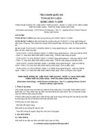
A scheme of the measurement set-up is given in Figure 1.
LICENSED TO MECON Limited. - RANCHI/BANGALORE
FOR INTERNAL USE AT THIS LOCATION ONLY, SUPPLIED BY BOOK SUPPLY BUREAU.
This part of IEC 61290 applies to optical amplifiers (OAs) using active fibres presently
commercially available containing rare-earth dopants.
61290-7-1 © IEC:2007
–7–
Optical
isolator
Optical
OPTICAL
source
SOURCE
C
A
B
Optical
power
meter
Optical
filter
IEC 664/98
Figure 1a – Optical filter calibration
Optical
source
C
OA
A
B
OA
Optical
under test
filter
Optical
power
meter
IEC 665/98
Figure 1b – Out-of-band insertion loss measurement
Figure 1 – Typical arrangement of the optical filter test apparatus
for out-of-band insertion loss measurements
The test equipment listed below, with the required characteristics, is needed:
a) optical source: the optical source shall generate a light at the out-of-band wavelength
specified in the relevant detail specification. Unless otherwise specified, the optical source
shall emit a continuous wave with the full width at half maximum of the spectrum narrower
than 1 nm (‡);
b) optical isolator: the polarization-dependent loss variation of the isolator, at the out-of-band
wavelength, shall be better than 0,2 dB (‡). Optical isolation shall be better than 40 dB (‡).
The reflectance from this device shall be smaller than –40 dB (‡) at each port;
c) optical filter: it shall be pass band at the out-of-band wavelength, and have a high loss over
the OA (optical amplifier) pump and signal wavelength ranges, in such a way as to render
the total power in these wavelength ranges more than 20 dB (‡) lower than the out-of-band
power after passing through the OA;
d) optical power meter: it shall have a measurement accuracy better than ±0,2 dB, irrespective
of the state of polarization, at the out-of-band wavelength of the OA;
e) optical fibre jumpers: the mode field diameter of the optical fibre jumpers used should be as
close as possible to that of fibres used at input and output ports of the OA. Their
reflectance shall be smaller than –40 dB (‡) at each port, and the length of each jumper
shall be less than 2 m.
5
Test sample
The OA shall operate as specified in the relevant detail specification.
LICENSED TO MECON Limited. - RANCHI/BANGALORE
FOR INTERNAL USE AT THIS LOCATION ONLY, SUPPLIED BY BOOK SUPPLY BUREAU.
Optical
isolator
–8–
61290-7-1 © IEC:2007
NOTE The operating conditions of the OA under test could be, for instance, the nominal operating conditions or
the unpowered conditions.
6
Procedure
This method permits determination of the OA out-of-band insertion losses according to the
procedures described below:
a) out-of-band insertion loss:
1) set the optical source at the out-of-band wavelength, as specified in the relevant detail
specification;
3) insert the OA under test, as shown in Figure 1b, and measure the optical power P 1 at
the out-of-band wavelength, with the optical power meter.
b) out-of-band reverse insertion loss:
As in a), but with the OA inserted with the input port used as output port and vice-versa.
7
Calculation
Calculation shall be carried out as indicated below.
a) Out-of-band insertion loss
Calculate the OA out-of-band insertion loss, L OB , from the power levels P 0 and P 1 (in dBm),
as:
L OB = P 0 – P 1 (dBm)
b) Out-of-band reverse insertion loss
As in a), taking into account that L OB represents, in this case, the out-of-band reverse
insertion loss of the OA.
8
Test results
Report the following information for each test.
a) Out-of-band insertion loss
The following details shall be presented:
1) arrangement of the test set-up;
2) spectral linewidth (full width at half maximum) of the optical source;
3) out-of-band wavelengths of the measurement;
4) indication of the optical pump power (if applicable);
5) ambient temperature (if required);
6) out-of-band insertion loss.
b) Out-of-band reverse insertion loss
In addition to details 1) to 5), previously listed for the out-of-band insertion loss, the
following shall be presented:
6) out-of-band reverse insertion loss.
LICENSED TO MECON Limited. - RANCHI/BANGALORE
FOR INTERNAL USE AT THIS LOCATION ONLY, SUPPLIED BY BOOK SUPPLY BUREAU.
2) calibrate the optical filter measuring the optical power at the out-of-band wavelength P 0
with the optical power meter, without the OA, as shown in Figure 1a;
61290-7-1 © IEC:2007
9
–9–
Electromagnetic compatibility (EMC) requirements
The devices and assemblies addressed by the present standard shall comply with suitable
requirements for electromagnetic compatibility (in terms of both emission and immunity),
depending on particular usage/environment in which they are intended to be installed or
integrated. Guidance on the drafting of such EMC requirements is provided in IEC Guide 107.
Guidance for electrostatic discharge (ESD) is still under study.
LICENSED TO MECON Limited. - RANCHI/BANGALORE
FOR INTERNAL USE AT THIS LOCATION ONLY, SUPPLIED BY BOOK SUPPLY BUREAU.
– 10 –
61290-7-1 © IEC:2007
Bibliography
IEC Guide 107, Electromagnetic compatibility – Guide to the drafting of electromagnetic
compatibility publications
IEC 60793-1(all parts), Optical fibres – Part 1: Measurement methods and test procedures
IEC 60825-1, Safety of laser products – Part 1: Equipment classification, requirements and
user's guide
IEC 60825-2, Safety of laser products – Part 2: Safety of optical fibre communication systems
(OFCS)
IEC/TR 61931, Fibre optic – Terminology
___________
LICENSED TO MECON Limited. - RANCHI/BANGALORE
FOR INTERNAL USE AT THIS LOCATION ONLY, SUPPLIED BY BOOK SUPPLY BUREAU.
IEC 60874-1, Connectors for optical fibres and cables – Part 1: Generic specification
LICENSED TO MECON Limited. - RANCHI/BANGALORE
FOR INTERNAL USE AT THIS LOCATION ONLY, SUPPLIED BY BOOK SUPPLY BUREAU.
– 12 –
61290-7-1 © CEI:2007
SOMMAIRE
AVANT-PROPOS .................................................................................................................. 13
INTRODUCTION ................................................................................................................... 15
Domaine d'application et objet ........................................................................................ 16
2
Références normatives ................................................................................................... 16
3
Termes abrégés ............................................................................................................. 16
4
Appareillage ................................................................................................................... 16
5
Echantillon d’essai .......................................................................................................... 17
6
Procédure....................................................................................................................... 18
7
Calculs ........................................................................................................................... 18
8
Résultats de l’essai......................................................................................................... 18
9
Exigences de compatibilité électromagnétique (CEM)...................................................... 19
Bibliographie ......................................................................................................................... 20
Figure 1 – Disposition typique de l’appareillage d’essai de filtre optique pour les
mesures de la perte d’insertion hors-bande ........................................................................... 17
LICENSED TO MECON Limited. - RANCHI/BANGALORE
FOR INTERNAL USE AT THIS LOCATION ONLY, SUPPLIED BY BOOK SUPPLY BUREAU.
1
61290-7-1 © CEI:2007
– 13 –
COMMISSION ÉLECTROTECHNIQUE INTERNATIONALE
____________
AMPLIFICATEURS OPTIQUES –
MÉTHODES D'ESSAI –
Partie 7-1: Pertes d'insertion hors-bande –
Méthode par puissance-mètre optique filtré
AVANT-PROPOS
2) Les décisions ou accords officiels de la CEI concernant les questions techniques représentent, dans la mesure
du possible, un accord international sur les sujets étudiés, étant donné que les Comités Nationaux intéressés
sont représentés dans chaque comité d’études.
3) Les publications CEI se présentent sous la forme de recommandations internationales et elles sont agréées
comme telles par les Comités nationaux de la CEI. Tous les efforts raisonnables sont entrepris afin que la CEI
s'assure de l'exactitude du contenu technique de ses publications; la CEI ne peut pas être tenue responsable de
l'éventuelle mauvaise utilisation ou interprétation qui en est faite par un quelconque utilisateur final.
4) Dans le but d'encourager l'unification internationale, les Comités Nationaux de la CEI s'engagent appliquer de
faỗon transparente, dans toute la mesure possible, les normes internationales de la CEI dans leurs normes
nationales et régionales. Toute divergence entre la norme de la CEI et la norme nationale ou régionale
correspondante doit être indiquée en termes clairs dans cette dernière.
5) La CEI n’a fixé aucune procédure concernant le marquage comme indication d’approbation et sa responsabilité
n’est pas engagée quand un matériel est déclaré conforme à l’une de ses normes.
6) Tous les utilisateurs doivent s'assurer qu'ils sont en possession de la dernière édition de cette publication.
7) Aucune responsabilité ne doit être imputée à la CEI, à ses administrateurs, employés, auxiliaires ou
mandataires, y compris ses experts particuliers et les membres de ses comités d'études et des Comités
nationaux de la CEI, pour tout préjudice causé en cas de dommages corporels et matériels, ou de tout autre
dommage de quelque nature que ce soit, directe ou indirecte, ou pour supporter les coûts (y compris les frais
de justice) et les dépenses découlant de la publication ou de l'utilisation de cette Publication de la CEI ou de
toute autre Publication de la CEI, ou au crédit qui lui est accordé.
8) L'attention est attirée sur les références normatives citées dans cette publication. L'utilisation de publications
référencées est obligatoire pour une application correcte de la présente publication.
9) L’attention est attirée sur le fait que certains des éléments de la présente publication CEI peuvent faire l’objet
de droits de propriété intellectuelle ou de droits analogues. La CEI ne saurait être tenue pour responsable de ne
pas avoir identifié de tels droits de propriété ou de ne pas avoir signalé leur existence.
La Norme internationale CEI 61290-7-1 a été établie par le sous-comité 86C: Systèmes et
dispositifs actifs à fibres optiques, du comité d'études 86 de la CEI: Fibres optiques.
Cette deuxième édition annule et remplace la première édition parue en 1998, dont elle
constitue une révision technique. Les changements les plus significatifs sont les suivants:
a) le titre a été changé afin d’être cohérent avec les autres documents de la série CEI
61290 ;
b) l’applicabilité a été étendue à tous les amplificateurs optiques disponibles sur le
marché, et non pas simplement aux amplificateurs à fibres optiques ;
c) l’Article 9, CEM, a été ajouté.
LICENSED TO MECON Limited. - RANCHI/BANGALORE
FOR INTERNAL USE AT THIS LOCATION ONLY, SUPPLIED BY BOOK SUPPLY BUREAU.
1) La CEI (Commission Electrotechnique Internationale) est une organisation mondiale de normalisation composée
de l'ensemble des comités électrotechniques nationaux (Comités nationaux de la CEI). La CEI a pour objet de
favoriser la coopération internationale pour toutes les questions de normalisation dans les domaines de
l'électricité et de l'électronique. A cet effet, la CEI – entre autres activités – publie des Normes internationales,
des Spécifications techniques, des Rapports techniques, des Spécifications accessibles au public (PAS) et des
Guides (ci-après dénommés "Publication(s) de la CEI"). Leur élaboration est confiée à des comités d'études,
aux travaux desquels tout Comité national intéressé par le sujet traité peut participer. Les organisations
internationales, gouvernementales et non gouvernementales, en liaison avec la CEI, participent également aux
travaux. La CEI collabore étroitement avec l'Organisation Internationale de Normalisation (ISO), selon des
conditions fixées par accord entre les deux organisations.
– 14 –
61290-7-1 © CEI:2007
La présente norme doit être utilisée conjointement à la CEI 61291-1. Elle a été établie sur la
base de la seconde édition (2006) de cette dernière.
Le texte de cette norme est issu des documents suivants:
CDV
Rapport de vote
86C/726/CDV
86C/741/RVC
Les rapports de vote indiqués dans le tableau ci-dessus donnent toute information sur le vote
ayant abouti à l'approbation de cette norme.
Cette publication a été rédigée selon les Directives ISO/CEI, Partie 2.
Le comité a décidé que le contenu de cette publication ne sera pas modifié avant la date du
résultat de la maintenance indiquée sur le site web de la CEI à l’adresse suivante:
"", dans les données liées à la publication spécifique. A cette date, la
publication sera:
•
•
•
•
reconduite;
supprimée;
remplacée par une édition révisée, ou
amendée.
LICENSED TO MECON Limited. - RANCHI/BANGALORE
FOR INTERNAL USE AT THIS LOCATION ONLY, SUPPLIED BY BOOK SUPPLY BUREAU.
Une liste de toutes les parties de la série CEI 61290, publiée sous le titre général
Amplificateurs optiques – Méthodes d’essais peut être consultée sur le site internet de la CEI.
61290-7-1 © CEI:2007
– 15 –
INTRODUCTION
La présente Norme internationale est consacrée au domaine des amplificateurs optiques. La
technologie des amplificateurs optiques se développe encore rapidement, de sorte que des
amendements et de nouvelles additions à cette norme sont à prévoir.
LICENSED TO MECON Limited. - RANCHI/BANGALORE
FOR INTERNAL USE AT THIS LOCATION ONLY, SUPPLIED BY BOOK SUPPLY BUREAU.
– 16 –
61290-7-1 © CEI:2007
AMPLIFICATEURS OPTIQUES –
MÉTHODES D'ESSAI –
Partie 7-1: Pertes d'insertion hors-bande –
Méthode par puissance-mètre optique filtré
1
Domaine d'application et objet
L'objet de la présente norme est d'établir des exigences uniformes pour des mesures précises
et fiables des paramètres d’AO donnés ci-dessous, par le biais de la méthode d'essai par
puissance-mètre optique filtré, tels qu’ils sont définis dans la CEI 61291-1:
a) perte d'insertion hors-bande;
b) perte d'insertion inverse hors-bande.
NOTE 1 La perte d’insertion hors-bande d’un AO est très dépendante de la configuration de l’amplificateur et de la
longueur d’onde hors-bande.
NOTE 2
2
Toutes les valeurs numériques suivies de (‡) sont des valeurs proposées.
Références normatives
Les documents de référence suivants sont indispensables pour l'application du présent
document. Pour les références datées, seule l’édition citée s’applique. Pour les références non
datées, la dernière édition du document de référence (y compris les éventuels amendements)
s'applique.
CEI 61291-1, Amplificateurs optiques – Partie 1: Spécification générique
3
Termes abrégés
Chaque abréviation introduite dans la présente norme est expliquée dans le texte, au moins
lors de sa première apparition. Cependant, pour une meilleure compréhension de l'ensemble
du texte, une liste de toutes les abréviations utilisées dans la présente norme est fournie ciaprès.
AO
Amplificateur optique
CEM
Compatibilité électromagnétique
ESD
Décharge électrostatique (electrostatic discharge)
4
Appareillage
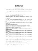
Un schéma de l’installation de mesure est représenté à la Figure 1.
LICENSED TO MECON Limited. - RANCHI/BANGALORE
FOR INTERNAL USE AT THIS LOCATION ONLY, SUPPLIED BY BOOK SUPPLY BUREAU.
La présente partie de la CEI 61290 s'applique aux amplificateurs optiques (AO) utilisant des
fibres actives, dopées aux terres rares, actuellement disponibles sur le marché.
61290-7-1 © CEI:2007
– 17 –
Isolateur
Optical
optique
isolator
Optical
OPTICAL
Source
source
optique
SOURCE
C
A
B
Optical
Puissancepower
mètre
meter
optique
Optical
Filtre
filter
optique
IEC 664/98
Figure
filtre optique
Figure1a
1a––Etalonnage
Optical filterdu
calibration
C
Optical
Source
source
optique
OA
AO
OA
AO
under
test
en essai
A
B
Optical
Puissancepower
mètre
meter
optique
Optical
Filtre
filter
optique
IEC 665/98
Figure
de lainsertion
perte d’insertion
hors-bande
Figure1b
1b––Mesure
Out-of-band
loss measurement
Figure 1 – Disposition typique de l’appareillage d’essai de filtre optique
pour les mesures de la perte d’insertion hors-bande
Le matériel d'essai énuméré ci-dessous, avec les caractéristiques requises, est nécessaire:
a) source optique: La source optique doit générer une lumière avec une longueur d’onde horsbande précisée dans la spécification particulière correspondante. Sauf spécification
contraire, la source optique doit émettre une onde continue avec une largeur spectrale à
mi-hauteur du spectre inférieure à 1 nm (‡);
b) isolateur optique: La variation des pertes dépendantes de la polarisation de l’isolateur doit
être inférieure à 0,2 dB (‡), à la longueur d’onde hors-bande. L’isolation optique doit être
supérieure à 40 dB (‡). La réflectance de ce dispositif doit être inférieure à –40 dB (‡) à
chaque port;
c) filtre optique: il doit être de type passe-bande à la longueur d’onde hors-bande, et doit
générer un fort affaiblissement sur les plages de longueur d'onde de pompage de l’AO
(amplificateur optique) et du signal, de faỗon restituer une puissance totale ces plages
de longueurs d’onde inférieure d’au moins 20 dB (‡) à la puissance hors-bande, en sortie
de l’AO;
d) puissance-mètre optique: Il doit avoir une incertitude de mesure de ±0,2 dB maximum,
indépendamment de l'état de polarisation, à la longueur d’onde hors-bande de l'AO;
e) jarretières en fibre optique: Il convient que le diamètre du champ de mode des jarretières
en fibre optique utilisées soit aussi proche que possible de celui des fibres aux ports
d'entrée et de sortie de l'AO. Leur réflectance doit être inférieure à –40 dB (‡) à chaque
port, et la longueur de chaque jarretière doit être inférieure à 2 m.
5
Echantillon d’essai
L’AO doit fonctionner selon ce qui est précisé dans sa spécification particulière applicable.
LICENSED TO MECON Limited. - RANCHI/BANGALORE
FOR INTERNAL USE AT THIS LOCATION ONLY, SUPPLIED BY BOOK SUPPLY BUREAU.
Optical
Isolateur
isolator
optique
– 18 –
61290-7-1 © CEI:2007
NOTE Les conditions de fonctionnement de l’AO en essai pourraient être, par exemple, les conditions de
fonctionnement nominales, ou les conditions hors puissance.
6
Procédure
Cette méthode permet la détermination des pertes d’insertion hors-bande de l’AO, selon les
procédures décrites ci-dessous:
a) perte d'insertion hors-bande:
1) régler la source optique à la longueur d’onde hors-bande précisée dans la spécification
particulière correspondante;
2) étalonner le filtre optique mesurant la puissance optique à la longueur d’onde horsbande P 0 avec le puissance-mètre optique, sans l’AO, comme illustré à la Figure 1a;
b) perte d'insertion inverse hors-bande:
Comme en a), mais avec l’AO inséré avec le port d’entrée utilisé comme port de sortie et
vice-versa.
7
Calculs
Les calculs ci-après doivent être effectués.
a) Perte d'insertion hors-bande
Calculer la perte d’insertion hors-bande de l’AO, L OB , à partir des niveaux de puissance P 0
et P 1 (en dBm), de la faỗon suivante:
L OB = P 0 – P 1 (dBm)
b) Perte d'insertion inverse hors-bande
Comme en a), en prenant en compte que L OB représente dans ce cas la perte d’insertion
inverse hors-bande de l'AO.
8
Résultats d’essai
Consigner les informations suivantes pour chaque essai.
a) Perte d'insertion hors-bande
Les précisions suivantes doivent être indiquées:
1) la configuration du montage d’essai;
2) la largeur de ligne spectrale de la source optique (largeur à mi-hauteur);
3) les longueurs d’onde hors-bande de la mesure;
4) l’indication de la puissance de pompe optique (si applicable);
5) la température ambiante (si nécessaire);
6) la perte d'insertion hors-bande.
b) Perte d'insertion inverse hors-bande
Les détails 1) à 5), précédemment cités pour la perte d’insertion hors-bande, doivent être
indiqués et, en plus:
6) la perte d'insertion inverse hors-bande.
LICENSED TO MECON Limited. - RANCHI/BANGALORE
FOR INTERNAL USE AT THIS LOCATION ONLY, SUPPLIED BY BOOK SUPPLY BUREAU.
3) insérer l’AO en essai, comme illustré à la Figure 1b, et mesurer la puissance optique P 1
à la longueur d’onde hors-bande, avec le puissance-mètre optique.