Schaum''s outline of signals and systems
Bạn đang xem bản rút gọn của tài liệu. Xem và tải ngay bản đầy đủ của tài liệu tại đây (6.28 MB, 483 trang )
SCHAUM'S OUTLINES OF
Theory and Problems of Signals and Systems
Hwei P. Hsu, Ph.D.
Professor of Electrical Engineering
Fairleigh Dickinson University
Start of Citation[PU]McGraw-Hill Professional[/PU][DP]1995[/DP]End of Citation
HWEI P. HSU is Professor of Electrical Engineering at Fairleigh Dickinson University. He received
his B.S. from National Taiwan University and M.S. and Ph.D. from Case Institute of Technology. He
has published several books which include Schaum's Outline of Analog and Digital Communications.
Schaum's Outline of Theory and Problems of
SIGNALS AND SYSTEMS
Copyright © 1995 by The McGraw-Hill Companies, Inc. All rights reserved. Printed in the United
States of America. Except as permitted under the Copyright Act of 1976, no part of this publication
may be reproduced or distributed in any form or by any means, or stored in a data base or retrieval
system, without the prior written permission of the publisher.
4 5 6 7 8 9 10 11 12 13 14 15 16 17 18 19 20 BAW BAW 9 9
ISBN 0-07-030641-9
Sponsoring Editor: John Aliano
Production Supervisor: Leroy Young
Editing Supervisor: Maureen Walker
Library of Congress Cataloging-in-Publication Data
Hsu, Hwei P. (Hwei Piao), date
Schaum's outline of theory and problems of signals and systems / Hwei P. Hsu.
p. cm.—(Schaum's outline series)
Includes index.
ISBN 0-07-030641-9
1. Signal theory (Telecommunication)—Problems, exercises, etc.
I. Title.
TK5102.92.H78 1995
621.382'23—dc20 94-44820
CIP
Start of Citation[PU]McGraw-Hill Professional[/PU][DP]1995[/DP]End of Citation
Preface
The concepts and theory of signals and systems are needed in almost all electrical engineering fields
and in many other engineering and scientific disciplines as well. They form the foundation for further
studies in areas such as communication, signal processing, and control systems.
This book is intended to be used as a supplement to all textbooks on signals and systems or for self-
study. It may also be used as a textbook in its own right. Each topic is introduced in a chapter with
numerous solved problems. The solved problems constitute an integral part of the text.
Chapter 1 introduces the mathematical description and representation of both continuous-time and
discrete-time signals and systems. Chapter 2 develops the fundamental input-output relationship for
linear time-invariant (LTI) systems and explains the unit impulse response of the system and
convolution operation. Chapters 3 and 4 explore the transform techniques for the analysis of LTI
systems. The Laplace transform and its application to continuous-time LTI systems are considered in
Chapter 3. Chapter 4 deals with the z-transform and its application to discrete-time LTI systems. The
Fourier analysis of signals and systems is treated in Chapters 5 and 6. Chapter 5 considers the Fourier
analysis of continuous-time signals and systems, while Chapter 6 deals with discrete-time signals and
systems. The final chapter, Chapter 7, presents the state space or state variable concept and analysis
for both discrete-time and continuous-time systems. In addition, background material on matrix
analysis needed for Chapter 7 is included in Appendix A.
I am grateful to Professor Gordon Silverman of Manhattan College for his assistance, comments, and
careful review of the manuscript. I also wish to thank the staff of the McGraw-Hill Schaum Series,
especially John Aliano for his helpful comments and suggestions and Maureen Walker for her great
care in preparing this book. Last, I am indebted to my wife, Daisy, whose understanding and constant
support were necessary factors in the completion of this work.
HWEI P. HSU
MONTVILLE, NEW JERSEY
Start of Citation[PU]McGraw-Hill Professional[/PU][DP]1995[/DP]End of Citation
To the Student
To understand the material in this text, the reader is assumed to have a basic knowledge of calculus,
along with some knowledge of differential equations and the first circuit course in electrical
engineering.
This text covers both continuous-time and discrete-time signals and systems. If the course you are
taking covers only continuous-time signals and systems, you may study parts of Chapters 1 and 2
covering the continuous-time case, Chapters 3 and 5, and the second part of Chapter 7. If the course
you are taking covers only discrete-time signals and systems, you may study parts of Chapters 1 and 2
covering the discrete-time case, Chapters 4 and 6, and the first part of Chapter 7.
To really master a subject, a continuous interplay between skills and knowledge must take place. By
studying and reviewing many solved problems and seeing how each problem is approached and how it
is solved, you can learn the skills of solving problems easily and increase your store of necessary
knowledge. Then, to test and reinforce your learned skills, it is imperative that you work out the
supplementary problems (hints and answers are provided). I would like to emphasize that there is no
short cut to learning except by "doing."
Start of Citation[PU]McGraw-Hill Professional[/PU][DP]1995[/DP]End of Citation
Contents
Chapter 1. Signals and Systems 1
1.1 Introduction 1
1.2 Signals and Classification of Signals 1
1.3 Basic Continuous-Time Signals 6
1.4 Basic Discrete-Time Signals 12
1.5 Systems and Classification of Systems 16
Solved Problems 19
Chapter 2. Linear Time-Invariant Systems 56
2.1 Introduction 56
2.2 Response of a Continuous-Time LTI System and the Convolution Integral 56
2.3 Properties of Continuous-Time LTI Systems 58
2.4 Eigenfunctions of Continuous-Time LTI Systems 59
2.5 Systems Described by Differential Equations 60
2.6 Response of a Discrete-Time LTI System and Convolution Sum 61
2.7 Properties of Discrete-Time LTI Systems 63
2.8 Eigenfunctions of Discrete-Time LTI Systems 64
2.9 Systems Described by Difference Equations 65
Solved Problems 66
Chapter 3. Laplace Transform and Continuous-Time LTI Systems 110
3.1 Introduction 110
3.2 The Laplace Transform 110
3.3 Laplace Transforms of Some Common Signals 114
3.4 Properties of the Laplace Transform 114
3.5 The Inverse Laplace Transform 119
3.6 The System Function 121
3.7 The Unilateral Laplace Transform 124
Solved Problems 127
Chapter 4. The z-Transform and Discrete-Time LTI Systems 165
4.1 Introduction 165
4.2 The z-Transform 165
4.3 z-Transforms of Some Common Sequences 169
4.4 Properties of the z-Transform 171
4.5 The Inverse z-Transform 173
4.6 The System Function of Discrete-Time LTI Systems 175
4.7 The Unilateral z-Transform 177
Solved Problems 178
Chapter 5. Fourier Analysis of Continuous-Time Signals and Systems 211
5.1 Introduction 211
5.2 Fourier Series Representation of Periodic Signals 211
5.3 The Fourier Transform 214
5.4 Properties of the Continuous-Time Fourier Transform 219
vii
5.5 The Frequency Response of Continuous-Time LTI Systems 223
5.6 Filtering 227
5.7 Bandwidth 230
Solved Problems 231
Chapter 6. Fourier Analysis of Discrete-Time Signals and Systems 288
6.1 Introduction 288
6.2 Discrete Fourier Series 288
6.3 The Fourier Transform 291
6.4 Properties of the Fourier Transform 295
6.5 The Frequency Response of Discrete-Time LTI Systems 300
6.6 System Response to Sampled Continuous-Time Sinusoids 302
6.7 Simulation 303
6.8 The Discrete Fourier Transform 305
Solved Problems 308
Chapter 7. State Space Analysis 365
7.1 Introduction 365
7.2 The Concept of State 365
7.3 State Space Representation of Discrete-Time LTI Systems 366
7.4 State Space Representation of Continuous-Time LTI Systems 368
7.5 Solutions of State Equations for Discrete-Time LTI Systems 371
7.6 Solutions of State Equations for Continuous-Time LTI Systems 374
Solved Problems 377
Appendix A. Review of Matrix Theory 428
A.1 Matrix Notation and Operations 428
A.2 Transpose and Inverse 431
A.3 Linear Independence and Rank 432
A.4 Determinants 433
A.5 Eigenvalues and Eigenvectors 435
A.6 Diagonalization and Similarity Transformation 436
A.7 Functions of a Matrix 437
A.8 Differentiation and Integration of Matrices 444
Appendix B. Properties of Linear Time-Invariant Systems and Various Transforms 445
B.1 Continuous-Time LTI Systems 445
B.2 The Laplace Transform 445
B.3 The Fourier Transform 447
B.4 Discrete-Time LTI Systems 449
B.5 The z-Transform 449
B.6 The Discrete-Time Fourier Transform 451
B.7 The Discrete Fourier Transform 452
B.8 Fourier Series 453
B.9 Discrete Fourier Series 454
Appendix C. Review of Complex Numbers 455
C.1 Representation of Complex Numbers 455
C.2 Addition, Multiplication, and Division 456
C.3 The Complex Conjugate 456
C.4 Powers and Roots of Complex Numbers 456
Appendix D. Useful Mathematical Formulas 458
D.1 Summation Formulas 458
D.2 Euler's Formulas 458
viii
D.3 Trigonometric Identities 458
D.4 Power Series Expansions 459
D.5 Exponential and Logarithmic Functions 459
D.6 Some Definite Integrals 460
Index 461
ix
Chapter
1
Signals and Systems
1.1
INTRODUCTION
The concept and theory of signals and systems are needed in almost all electrical
engineering fields and in many other engineering and scientific disciplines as well. In this
chapter we introduce the mathematical description and representation of signals and
systems and their classifications. We also define several important basic signals essential to
our studies.
1.2
SIGNALS AND CLASSIFICATION OF SIGNALS
A
signal is a function representing a physical quantity or variable, and typically it
contains information about the behavior or nature of the phenomenon. For instance, in a
RC
circuit the signal may represent the voltage across the capacitor or the current flowing
in the resistor. Mathematically, a signal is represented as a function of an independent
variable t. Usually t represents time. Thus, a signal is denoted by x(t).
A. Continuous-Time and Discrete-Time Signals:
A
signal x(t) is a continuous-time signal if t is a continuous variable.
If
t is a discrete
variable, that is, x(t) is defined at discrete times, then x(t) is a discrete-time signal. Since a
discrete-time signal is defined at discrete times, a discrete-time signal is often identified as
a sequence of numbers, denoted by {x,) or x[n], where n
=
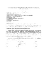
integer. Illustrations of a
continuous-time signal x(t) and of a discrete-time signal x[n] are shown in Fig.
1-1.
(4
(b)
Fig.
1-1
Graphical representation
of
(a)
continuous-time and
(6)
discrete-time signals.
A
discrete-time signal x[n] may represent a phenomenon for which the independent
variable is inherently discrete. For instance, the daily closing stock market average is by its
nature a signal that evolves at discrete points in time (that is, at the close of each day). On
the other hand a discrete-time signal x[n] may be obtained by sampling a continuous-time
1
SIGNALS AND SYSTEMS
[CHAP.
1
signal x(t) such as
x(to), +,)'
.
7
~(t,),
.
.
*
or in
a
shorter form as
x[O], x[l],
,
x[n],
.
or xo, x~,.
. .
,
x,,
.
.
.
where we understand that
x, =x[n] =x(t,)
and x,'s are called samples and the time interval between them is called the sampling
interval. When the sampling intervals are equal (uniform sampling), then
x,,
=x[n] =x(nT,)
where the constant
T,
is the sampling interval.
A
discrete-time signal x[n] can be defined in two ways:
1.
We can specify a rule for calculating the nth value of the sequence. For example,
2. We can also explicitly list the values of the sequence. For example, the sequence
shown in Fig. l-l(b) can be written as
(x,)
=
( ,
0,0,1,2,2,1,0,1,0,2,0,0
,
)
T
We use the arrow to denote the
n
=
0 term. We shall use the convention that
if
no
arrow is indicated, then the first term corresponds to n
=
0 and all the values of the
sequence are zero for n
<
0.
(c,)
=
a(a,)
+
C,
=
aa,
a
=
constant
B.
Analog and Digital Signals:
If a continuous-time signal x(l) can take on any value in the continuous interval (a, b),
where a may be
-
03
and b may be
+
m,
then the continuous-time signal x(t) is called an
analog signal. If a discrete-time signal x[n] can take on only a finite number of distinct
values, then we call this signal
a
digital signal.
C. Real and Complex Signals:
A
signal x(t) is a real signal
if
its value is a real number, and a signal x(t) is a complex
signal if its value is a complex number.
A
general complex signal ~(t) is a function of the
CHAP.
11
form
SIGNALS
AND
SYSTEMS
x(t) =x,(t) +ix2(t)
where
x,( t)
and
x2( t)
are real signals and
j
=
m.
Note that in
Eq.
(I.l)
t
represents either a continuous or a discrete variable.
D. Deterministic and Random Signals:
Deterministic
signals are those signals whose values are completely specified for any
given time. Thus, a deterministic signal can be modeled by a known function of time
I.
Random
signals are those signals that take random values at any given time and must be
characterized statistically. Random signals will not be discussed in this text.
E. Even and Odd Signals:
A
signal
x(t)
or
x[n]
is referred to as an
even
signal if
x(-t) =x(r)
x[-n] =x[n]
A
signal
x(t)
or
x[n]
is referred to as an
odd
signal if
Examples of even
x(-t)
=
-x(t)
x[-n]
=
-x[n]
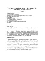
and odd signals are shown in Fig.
1-2.
(4
(4
Fig.
1-2
Examples of even signals
(a
and
6)
and odd signals
(c
and
dl.
4
SlGNALS
AND
SYSTEMS
[CHAP.
1
Any signal
x(t)
or
x[n]
can be expressed as a sum of two signals, one of which is even
and one of which is odd. That is,
where
xe(t)
=
${x(t) +x(-t)]
even part of
x(t)
xe[n]
=
i{x[n] +x[-n])
even part of
x[n]
(1.5)
x,(t)
=
${x(t) -x(-t))
odd part of
x(t
)
x,[n]
=
${x[n] -x[-n])
odd part of
x[n]
(
1.6
)
Note that the product of two even signals or of two odd signals is an even signal and
that the product of an even signal and an odd signal is an odd signal (Prob.
1.7).
F.
Periodic and Nonperiodic Signals:
A continuous-time signal
x(t)
is said to be
periodic
with
period
T
if there is a positive
nonzero value of
T
for which
x(t
+
T)
=x(t)
all
t
(1.7)
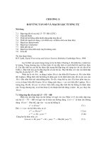
An example of such a signal is given in Fig.
1-3(a).
From
Eq.
(1.7)
or Fig.
1-3(a)
it follows
that
for all
t
and any integer
m.
The
fundamental
period
T,
of
x(t)
is the smallest positive
value of
T
for which
Eq.
(1.7)
holds. Note that this definition does not work for a constant
(b)
Fig.
1-3
Examples
of
periodic signals.
CHAP.
11
SIGNALS
AND
SYSTEMS
5
signal x(t) (known as a dc signal). For a constant signal x(t) the fundamental period is
undefined since x(t) is periodic for any choice of
T
(and so there is no smallest positive
value). Any continuous-time signal which is not periodic is called a nonperiodic (or
aperiodic
)
signal.
Periodic discrete-time signals are defined analogously.
A
sequence (discrete-time
signal) x[n] is periodic with period
N
if there is a positive integer
N
for which
x[n
+
N]
=x[n] all n (1.9)
An example of such a sequence is given in Fig.
1-3(b).
From Eq. (1.9) and Fig.
1-3(b)
it
follows that
for all n and any integer m. The fundamental period
No
of x[n] is the smallest positive
integer
N
for which Eq. (1.9) holds. Any sequence which is not periodic is called a
nonperiodic (or aperiodic sequence.
Note that a sequence obtained by uniform sampling of a periodic continuous-time
signal may not be periodic (Probs. 1.12 and 1.13). Note also that the sum of two
continuous-time periodic signals may not be periodic but that the sum of two periodic
sequences is always periodic (Probs. 1.14 and 1 .l5).
G.
Energy
and
Power
Signals:
Consider v(t) to be the voltage across a resistor
R
producing a current dt). The
instantaneous power p( t) per ohm is defined as
Total energy
E
and average power
P
on a per-ohm basis are
3:
E=[
i2(t)dt joules
-?O
i2(t) dt watts
For an arbitrary continuous-time signal x(t), the normalized energy content
E
of x(t) is
defined as
The normalized average power
P
of x(t) is defined as
Similarly, for a discrete-time signal x[n], the normalized energy content
E
of x[n] is
defined as
6
SIGNALS
AND
SYSTEMS
[CHAP.
1
The normalized average power
P
of x[n] is defined as
1
P
=
lim
-
N+-
2N
+
1
,,=
-N
Based on definitions (1.14) to (1.17), the following classes of signals are defined:
1.
x(t) (or x[n]) is said to be an energy signal (or sequence)
if
and only if
0
<
E
<
m, and
so
P
=
0.
2.
x(t) (or x[n]) is said to be a power signal (or sequence) if and only if
0
<
P
<
m, thus
implying that
E
=
m.
3.
Signals that satisfy neither property are referred to as neither energy signals nor power
signals.
Note that a periodic signal is a power signal
if
its energy content per period is finite, and
then the average power of this signal need only be calculated over a period (Prob. 1.18).
1.3
BASIC CONTINUOUS-TIME SIGNALS
A. The Unit Step Function:
The unit step function u(t), also known as the Heaciside unit function, is defined as
which is shown in Fig. 1-4(a). Note that it is discontinuous at t
=
0
and that the value at
t
=
0
is undefined. Similarly, the shifted unit step function u(t
-
to) is defined as
which is shown in Fig. 1-4(b).
(a)
(b)
Fig.
1-4
(a)
Unit step function;
(b)
shifted unit step function.
B.
The Unit Impulse Function:
The unit impulse function 6(t), also known as the Dirac delta function, plays a central
role in system analysis. Traditionally, 6(t) is often defined as the limit of a suitably chosen
conventional function having unity area over an infinitesimal time interval as shown in
CHAP.
11
SIGNALS
AND
SYSTEMS
Fig.
1-5
Fig.
1-5
and possesses the following properties:
But an ordinary function which is everywhere
0
except at a single point must have the
integral
0
(in the Riemann integral sense). Thus, S(t) cannot be an ordinary function and
mathematically
it
is defined by
where 4(t) is any regular function continuous at t
=
0.
An alternative definition of S(t) is given by
Note that
Eq.
(1.20) or (1.21) is a symbolic expression and should not be considered an
ordinary Riemann integral. In this sense, S(t) is often called a generalized function and
4(t) is known as a testing function.
A
different class of testing functions will define a
different generalized function (Prob.
1.24).
Similarly, the delayed delta function 6(t
-
I,)
is
defined by
m
4(t)W
-
to) dt
=
4Po)
(1.22)
where 4(t) is any regular function continuous at
t
=
to. For convenience, S(t) and 6(t- to)
are depicted graphically as shown in Fig.
1-6.
SIGNALS AND SYSTEMS
[CHAP.
1
(a)
(b)
Fig.
1-6
(a)
Unit impulse function;
(b)
shifted unit impulse function.
Some additional properties of
S(t)
are
S(-
t)
=
S(t)
x(t)S(t)
=
x(O)S(t)
if
x(t)
is continuous at
t
=
0.
x(t)S(t
-to)
=x(to)6(t
-
t,)
if
x(t)
is continuous at
t
=
to.
Using Eqs.
(1.22)
and
(
1.241,
any continuous-time signal
x(t
can be expressec
Generalized Derivatives:
If
g(
t
)
is
a
generalized function, its nth generalized derivative
g("Y
t
)
=
dng(
t
)/dt
"
is
defined by the following relation:
where
4(t)
is a testing function which can be differentiated an arbitrary number of times
and vanishes outside some fixed interval and
@"'(t)
is the nth derivative of
4(t).
Thus, by
Eqs.
(
1.28)
and
(1.20)
the derivative of
S(
t)
can be defined as
where
4(t)
is a testing function which is continuous at
t
=
0
and vanishes outside some
fixed interval and
$(0)
=
d4(t)/dtl,=o.
Using Eq.
(1.28),
the derivative of
u(t)
can be
shown to be
S(t)
(Prob.
1.28);
that is,
CHAP.
11
SIGNALS
AND
SYSTEMS
Then the unit step function
u(t)
can be expressed as
(t)
=
S(r) di (1.31)
-
m
Note that the unit step function
u(t)
is discontinuous at
t
=
0;
therefore, the derivative of
u(t)
as shown in
Eq.
(1.30)
is not the derivative of a function in the ordinary sense and
should be considered a generalized derivative in the sense of a generalized function. From
Eq.
(1.31)
we see that
u(t)
is undefined at
t
=
0
and
by
Eq.
(1.21)
with
$(t)
=
1.
This result is consistent with the definition
(1.18)
of
u(t).
C. Complex Exponential Signals:
The
complex exponential
signal
Fig.
1-7
(a)
Exponentially increasing sinusoidal signal;
(b)
exponentially decreasing sinusoidal signal.
10
SIGNALS AND SYSTEMS
[CHAP.
1
is an important example of a complex signal. Using Euler's formula, this signal can be
defined as
~(t)
=
eiUo'
=
cos o,t
+
jsin w0t
(1.33)
Thus, x(t) is a complex signal whose real part is cos mot and imaginary part is sin oot. An
important property of the complex exponential signal x(t) in Eq. (1.32) is that it is
periodic. The fundamental period To of x(t) is given by (Prob.
1.9)
Note that x(t) is periodic for any value of
o,.
General Complex Exponential Signals:
Let
s
=
a
+
jw
be a complex number. We define x(t) as
~(t)
=
eS'
=
e("+~")'
=
e"'(cos ot
+
j
sin wt
)
(1 -35)
Then signal x(t) in
Eq.
(1.35) is known as a general complex exponential signal whose real
part eu'cos ot and imaginary part eu'sin wt are exponentially increasing
(a
>
0)
or
decreasing (a
<
0)
sinusoidal signals (Fig.
1-7).
Real Exponential Signals:
Note that if
s
=
a
(a real number), then
Eq.
(1.35) reduces to a real exponential signal
x(t)
=
em' (1.36)
(b)
Fig.
1-8
Continuous-time real exponential signals.
(a)
a
>
0; (b)
a
<
0.
CHAP.
11
SIGNALS
AND
SYSTEMS
11
As illustrated in Fig.
1-8,
if
a
>
0,
then x(f
)
is a growing exponential; and if
a
<
0,
then
x(t) is a decaying exponential.
D.
Sinusoidal Signals:
A continuous-time sinusoidal signal can be expressed as
where
A
is
the amplitude (real),
w,
is the radian frequency in radians per second, and
8
is
the phase angle in radians. The sinusoidal signal x(t) is shown in Fig. 1-9, and it is periodic
with fundamental period
The reciprocal of the fundamental period To is called the fundamental frequency fo:
fo=-
h ertz (Hz)
7.0
From Eqs. (1.38) and (1.39) we have
which is called the fundamental angular frequency. Using Euler's formula, the sinusoidal
signal in
Eq.
(1.37) can be expressed as
where "Re" denotes "real part of." We also use the notation
"Im"
to denote "imaginary
part of." Then
Fig.
1-9
Continuous-time sinusoidal signal.
12
SIGNALS AND SYSTEMS
[CHAP.
1
1.4
BASIC DISCRETE-TIME SIGNALS
A. The Unit Step Sequence:
The unit step sequence u[n] is defined as
which is shown in Fig. 1-10(a). Note that the value of u[n] at n
=
0
is defined [unlike the
continuous-time step function u(f) at t
=
01
and equals unity. Similarly, the shifted unit step
sequence ii[n
-
k] is defined as
which is shown in Fig. 1-lO(b).
(a)
(b)
Fig.
1-10
(a)
Unit step sequence; (b) shifted unit step sequence.
B.
The Unit Impulse Sequence:
The unit impulse (or unit sample) sequence 6[n]
is
defined as
which is shown in Fig. 1-ll(a). Similarly, the shifted unit impulse (or sample) sequence
6[n
-
k] is defined as
which is shown in Fig. 1-1 l(b).
(a)
(b)
Fig.
1-11
(a)
Unit impulse (sample) sequence; (6) shifted unit impulse sequence.
CHAP.
11
SIGNALS
AND
SYSTEMS
13
Unlike the continuous-time unit impulse function S(f),
S[n]
is defined without mathe-
matical complication or difficulty. From definitions (1.45) and (1.46) it is readily seen that
which are the discrete-time counterparts of Eqs. (1.25) and (1.26), respectively. From
definitions (1.43) to (1.46),
6[n]
and
u[n]
are related by
which are the discrete-time counterparts of Eqs. (1.30) and (1.31), respectively.
Using definition (1.46), any sequence
x[n]
can be expressed as
which corresponds to Eq. (1.27) in the continuous-time signal case.
C. Complex Exponential Sequences:
The
complex exponential
sequence is of the form
x[n]
=e~n~"
(1.49)
(1 SO)
Again, using Euler's formula,
x[n]
can be expressed as
x [n]
=
eJnnn
=
cos
Ron
+
j
sin
Ron
(1.53)
Thus
x[n]
is a complex sequence whose real part is cos
Ron
and imaginary part is sin
Ron.
In order for
ejn@
to be periodic with period
N
(>
O),
Ro
must satisfy the following
condition (Prob. 1.1 1):
no
m
=-
m
=
positive integer
2r
N
Thus the sequence
eJnon
is not periodic for any value of
R,.
It is periodic only if
R,/~IT
is
a rational number. Note that this property is quite different from the property that the
continuous-time signal
eJwo'
is periodic for any value of
o,.
Thus, if
R,
satisfies the
periodicity condition in Eq.
(1.54),
!&
f
0,
and
N
and
m
have no factors in common, then
the fundamental period of the sequence
x[n]
in
Eq.
(1.52)
is
No
given by
Another very important distinction between the discrete-time and continuous-time
complex exponentials is that the signals
el"o'
are all distinct for distinct values of
w,
but
that this is not the case for the signals
ejRon.
SIGNALS AND SYSTEMS
[CHAP.
1
0
0
*
.
.
.
.
.
.
b
n
0
b
(4
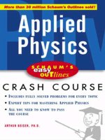
Fig.
1-12
Real
exponential
sequences.
(a)
a
>
1;
(b)
1
>
a
>
0;
(c)
0
>
a
>
-
1;
(dl
a
<
-
1.