ASTM A370-22. Standard Test Methods and Definitions for Mechanical Testing of Steel Products
Bạn đang xem bản rút gọn của tài liệu. Xem và tải ngay bản đầy đủ của tài liệu tại đây (2.92 MB, 51 trang )
c6
This international standard was developed in accordance with internationally recognized principles on standardization established in the Decision on Principles for the
Development of International Standards, Guides and Recommendations issued by the World Trade Organization Technical Barriers to Trade (TBT) Committee.
�u117
Designation: A370- 22
INTERNATIONAL
Standard Test Methods and Definitions for
Mechanical Testing of Steel Products 1
This standard is issued u nder the fixed designation A370; the num ber im mediately following the designation indicates the year of
orig inal a doption or, in the case of revision, the year of last revision. A number in parentheses indicates the year of last reapproval. A
superscript epsilon (e) ind icates an e ditorial change since the last revision or reapproval.
This standard has been approved for use by agencies of the U.S. Department of Defense.
1. Scope*
1 . 1 These test methods2 cover procedures and definitions
for the mechanical testing of steels, stainless steels, and related
alloys. The various mechanical tests herein described are used
to determine properties required in the product specifications.
Variations in testing methods are to be avoided, and standard
methods of testing are to be followed to obtain reproducible
and comparable results. In those cases in which the testing
requirements for certain products are unique or at variance with
these general procedures, the product specification testing
requirements shall control.
1 .2 The following mechanical tests are described:
Sections
7 to 1 4
15
16
17
18
19
20 to 30
32
Tension
Bend
Hardness
Brine II
Rockwell
Portable
Impact
Keywords
1 .3 Annexes covering details peculiar to certain products
are appended to these test methods as follows:
Bar Products
Tubular Products
Fasteners
Round Wire Products
Significance of Notched-Bar Impact Testing
Converting Percentage Elongation of Round Specimens to
Equivalents for Flat Specimens
Annex
Annex A 1
Annex A2
Annex A3
Annex A4
Annex A5
Annex A6
Testing Multi-Wire Strand
Rounding of Test Data
Methods for Testing Steel Reinforcing Bars
Procedure for Use and Control of Heat-cycle Simulation
Annex A?
Annex AS
Annex A9
Annex A 1 0
1 .4 The values stated in inch-pound units are to be regarded
as standard. The values given in parentheses are mathematical
conversions to SI units that are provided for information only
and are not considered standard.
1 .5 When these test methods are referenced in a metric
product specification, the yield and tensile values may be
determined in inch-pound (ksi) units then converted into SI
(MPa) units. The elongation determined in inch-pound gauge
lengths of 2 or 8 in. may be reported in SI unit gauge lengths
of 50 or 200 mm, respectively, as applicable. Conversely, when
these test methods are referenced in an inch-pound product
specification, the yield and tensile values may be determined in
SI units then converted into inch-pound units. The elongation
determined in SI unit gauge lengths of 50 or 200 mm may be
reported in inch-pound gauge lengths of 2 or 8 in., respectively,
as applicable.
1 . 5 . 1 The specimen used to determine the original units
must conform to the applicable tolerances of the original unit
system given in the dimension table not that of the converted
tolerance dimensions.
NoTE !-This is due to the specimen SI dimensions and tolerances
being hard conversions when this is not a dual standard. The user is
directed to Test Methods A I 058 if the tests are required in Sl units.
1 .6 Attention is directed to ISO/IEC 1 7025 when there may
be a need for information on criteria for evaluation of testing
laboratories.
1
These te st methods and de finitions are under the juri sdiction o f ASTM
Committee A O I on Steel, Sta inless Steel and Related Alloys and are the direct
responsi bility of Su bcommittee A 0 1 . 1 3 on Mechanical and Chemical Testing and
Processing Methods of Steel Products and Pro cesses.
Curre nt edition approved Oct . I , 2 022. Pu blished November 2022. Ori ginally
approved in 1 9 53. Last previous edition approved in 2 02 1 as A370-2 1 . DO!:
I
0. 1 520/A 037 0-22.
2 For ASME
Boiler and Pressure Vessel Code appl i cations see related Specifi
cation SA-370 in Se ction II of that Code.
1 .7 This standard does not purport to address all of the
safety concerns, if any, associated with its use. It is the
responsibility of the user of this standard to establish appro
priate safety, health, and environmental practices and deter
mine the applicability of regulatory limitations prior to use.
1 .8 This international standard was developed in accor
dance with internationally recognized principles on standard
ization established in the Decision on Principles for the
Development of International Standards, Guides and Recom
mendations issued by the World Trade Organization Technical
Barriers to Trade (TBT) Committee.
*A Summary of Changes section appears at the end of this standard
Copyright© ASTM International, 100 Barr Harbor Drive, PO Box C700, West Conshohocken, PA
Eqr{tkijfd{'CUVO"Kpv)n"'cnn'tkij vu"tgugtxgft,'Vjw'Pqx'39"32<63<73' 1 OV'4244
�n\/nnnrfnf1 rl�n11nf"rlf
19428-2959.
United States
0
A370-22
2. Referenced Documents
3 . 1 . 1 For definitions of terms pertaining to mechanical
testing of steel products not otherwise listed in this section,
reference shall be made to Terminology E6 and Terminology
A94 1 .
3 . 2 Definitions of Terms Specific to This Standard:
3 . 2. 1 fixed-location hardness testing machine, n-a hard
ness testing machine that is designed for routine operation in a
fixed-location by the users and is not designed to be
transported, or carried, or moved.
3 . 2. 1 . 1 Discussion-Typically due to its heavy weight and
large size, a fixed-location hardness testing machine is placed
in one location and not routinely moved.
3
2 . 1 ASTM Standards:
A623 Specification for Tin Mill Products, General Require
ments
A623M Specification for Tin Mill Products, General Re
quirements [Metric]
A833 Test Method for Indentation Hardness of Metallic
Materials by Comparison Hardness Testers
A94 1 Terminology Relating to Steel, Stainless Steel, Related
Alloys, and Ferroalloys
A956/A956M Test Method for Leeb Hardness Testing of
Steel Products
A l 038 Test Method for Portable Hardness Testing by the
Ultrasonic Contact Impedance Method
A l 058 Test Methods for Mechanical Testing of Steel
Products-Metric
A 1 06 1 /A l 06 1 M Test Methods for Testing Multi-Wire Steel
Prestressing Strand
E4 Practices for Force Calibration and Verification of Test
ing Machines
E6 Terminology Relating to Methods of Mechanical Testing
E8/E8M Test Methods for Tension Testing of Metallic Ma
terials
E 1 0 Test Method for Brinell Hardness of Metallic Materials
E 1 8 Test Methods for Rockwell Hardness of Metallic Ma
terials
E23 Test Methods for Notched Bar Impact Testing of Me
tallic Materials
E29 Practice for Using Significant Digits in Test Data to
Determine Conformance with Specifications
E83 Practice for Verification and Classification of Exten
someter Systems
E l l O Test Method for Rockwell and Brinell Hardness of
Metallic Materials by Portable Hardness Testers
E 1 90 Test Method for Guided Bend Test for Ductility of
Welds
E290 Test Methods for Bend Testing of Material for Ductil
ity
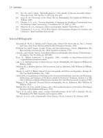
3 . 2. 2 longitudinal test, n-unless specifically defined
otherwise, signifies that the lengthwise axis of the specimen is
parallel to the direction of the greatest extension of the steel
during rolling or forging.
3 . 2.2.1 Discussion-The stress applied to a longitudinal
tension test specimen is in the direction of the greatest
extension, and the axis of the fold of a longitudinal bend test
specimen is at right angles to the direction of greatest extension
(see Fig. 1 , Fig. 2a, and Fig. 2b).
3 . 2.3 portable hardness testing machine, n-a hardness
testing machine that is designed to be transported, carried, set
up, and that measures hardness in accordance with the test
methods in Section 1 9.
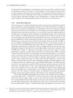
3 . 2.4 radial test, n-unless specifically defined otherwise,
signifies that the lengthwise axis of the specimen is perpen
dicular to the axis of the product and coincident with one of the
radii of a circle drawn with a point on the axis of the product
as a center (see Fig. 2a).
3.2 . 5 tangential test, n-unless specifically defined
otherwise, signifies that the lengthwise axis of the specimen
perpendicular to a plane containing the axis of the product and
tangent to a circle drawn with a point on the axis of the
productas a center (see Fig. 2a, Fig. 2b, Fig. 2c, and Fig. 2d).
�·/�::;:::�7
::::;:
2.2 ASME Document:4
ASME B oiler and Pressure Vessel Code, Section VIII,
Division I, Part UG-8
LONG!nJDINAl SPECIMEN
,.......
.?
LONGTIUDINAL FIATTENSION TEST
1
2.3 ISO Standard:5
• ...... n
�
�
LONG!nJDINAl ROUND TENSION TEST
ISO/IEC 1 7025 General Requirements for the Competence
of Testing and Calibration Laboratories
lONG!nJDINAl
BCNDTEST
- INDICATES ROlliNG DIRKTJON
OR EXTENSION.
3. Terminology
3 . 1 Definitions:
u- o
lONG!nJDINAl
IMPACT TEST
3 For referenced A S TM sta ndards, visit the ASTM we bsite, www.astm.org, or
contact ASTM C usto mer Service at service@ast m.org. For
Annual Book of ASTM
Standards volume i nformation, refer to the stan dard's Doc ument S ummary page on
the A S TM website .
4
Available fro m American Society of Mechanical Engineers (ASM E), A S M E
International Head quarters, Two Park Ave., New York, N Y 1 00 1 6-5990, http://
www.asme.org.
5 Available
fro m International
Organi zation for Standardi zation (IS O), I S O
FIG . 1 Relation of Test Coupons and Test Specimens to Rolling
C e ntral Secretariat, BIBC II, Chemi n de Blan donnet 8 , C P 40 I , I 2 I 4 Vernier,
Direction or Extension (Applicable to General Wrought Products)
Geneva, S witzerland, http: //www. i so.org.
2
Eqr{tkijv"d{"CUVO"Kpv)n..cm"tkijvu"tgugtxgft�"Vjw"Pqx"39"32<63<73" 1 OV"4244
Fqypnqcfgfl rtkpvgf"d{
Uj cp i j ck"Ucqvqp i "Wpkxgtukv{.. Uj cp i j ck"Ucqvqp i "Wpkxgtukv{ +"rwtuwcpv"vq"Nkegpug"C i tggogp\IJ"Pq"hwtvj gt"tgrtqfwevkqpu"cwvj qtk 1 gfO
0
v-
Tangential
�--'--'� Test
A370-22
Prolongation
I
I
I
I
- �
1
I
I
I
Radial Test
j
Et �
(a) Shafts and Rotors
---- - ---------
,: -
Prolongation
_______________
______
-
-
-
-
-----------
- ------
- I -
,':
"
'; al
.
Longitudinal Test
(b)
Prolongation
.�
I
I
I
I
,,
,,,,-
'
-
--,,
�
Tangential Test
-j
t
Hollow Forgings
,
'
,,/
'
'
\
\
\
I
I
.----1
I
I
I
I
/
Tangential Test
(c) Disk Forgings
r::_ Prolongation
t-
8:1
·�'
I
_J
'
Tangential Test
(d) Ring Forgings
FIG. 2 Location of Longitudinal Tension Test Specimens in Rings Cut From Tubular Products
3 . 2 . 7 transverse test, n-unless specifically defined
otherwise, signifies that the lengthwise axis of the specimen is
right angles to the direction of the greatest extension of the
steel during rolling or forging.
3.2.6 transition temperature, n-for specification purposes,
the transition temperature is the temperature at which the
designated material test value equals or exceeds a specified
minimum test value.
3 .2.6. 1 Discussion-Some of the many definitions of tran
sition temperature currently being used are: ( 1) the lowest
temperature at which the specimen exhibits 1 00 % fibrous
fracture, (2) the temperature where the fracture shows a 50 %
crystalline and a 50 % fibrous appearance, (3) the temperature
corresponding to the energy value 50 % of the difference
between values obtained at 1 00 and 0 % fibrous fracture, and
(4) the temperature corresponding to a specific energy value.
3.2.7. 1 Discussion-The stress applied to a transverse ten
sion test specimen is at right angles to the greatest extension,
and the axis of the fold of a transverse bend test specimen is
parallel to the greatest extension (see Fig. 1 ).
3
Eqr{tkijv"d{"CUVO"Kpv)n"'cm"tkijvu"tgugtxgft�"Vjw"Pqx"39"32<63<73" I OV"4244
Fqypnqcfgfl rtkpvgf"d{
Uj cp i j ck"Ucqvqp i "Wpkxgtukv{"'Uj cp i j ck"Ucqvqp i "Wpkxgtukv{ +"rwtuwcpv"vq"Nkegpug"C i tggogp\IJ"Pq"hwtvj gt"tgrtqfwevkqpu"cwvj qtk 1 gfO
0
A370-22
inhomogeneity, anisotropic structure, natural aging of select
alloys, further processing not included in the specification,
sampling limitations, and measuring equipment calibration
uncertainty. There is statistical variation in all aspects of
mechanical testing and variations in test results from prior tests
are expected. An understanding of possible reasons for devia
tion from specified or expected test values should be applied in
interpretation of test results.
3 . 3 Definition of Terms Specific to the Procedure for Use
and Control of Heat-cycle Simulation (See Annex A9):
3 .3 . 1 master chart, n-a record of the heat treatment re
ceived from a forging essentially identical to the production
forgings that it will represent.
3 . 3 . 1 . 1 Discussion-It is a chart of time and temperature
showing the output from thermocouples imbedded in the
forging at the designated test immersion and test location or
locations .
5. General Precautions
3 . 3 . 2 program chart, n-the metallized sheet used t o pro
gram the simulator unit.
3.3 .2. 1 Discussion-Time-temperature data from the master
chart are manually transferred to the program chart.
5.1 Certain methods of fabrication, such as bending,
forming, and welding, or operations involving heating, may
affect the properties of the material under test. Therefore, the
product specifications cover the stage of manufacture at which
mechanical testing is to be performed. The properties shown by
testing prior to fabrication may not necessarily be representa
tive of the product after it has been completely fabricated.
3 . 3 . 3 simulator chart, n-a record of the heat treatment that
a test specimen had received in the simulator unit.
3 . 3 . 3 . 1 Discussion-It is a chart of time and temperature
and can be compared directly to the master chart for accuracy
of duplication.
5 . 2 Improperly machined specimens should be discarded
and other specimens substituted.
3 . 3 .4 simulator cycle, n-one continuous heat treatment of a
set of specimens in the simulator unit.
3 . 3 .4 . 1 Discussion-The cycle includes heating from
ambient, holding at temperature, and cooling. For example, a
simulated austenitize and quench of a set of specimens would
be one cycle; a simulated temper of the same specimens would
be another cycle.
5 . 3 Flaws in the specimen may also affect results. If any test
specimen develops flaws, the retest provision of the applicable
product specification shall govern.
5 . 4 If any test specimen fails because of mechanical reasons
such as failure of testing equipment or improper specimen
preparation, it may be discarded and another specimen taken.
4. Significance and Use
6. Orientation of Test Specimens
6. 1 The terms "longitudinal test" and "transverse test" are
used only in material specifications for wrought products and
are not applicable to castings. When such reference is made to
a test coupon or test specimen, see Section 3 for terms and
definitions.
4 . 1 The primary use of these test methods is testing to
determine the specified mechanical properties of steel, stainless
steel, and related alloy products for the evaluation of confor
mance of such products to a material specification under the
j urisdiction of ASTM Committee A0 1 and its subcommittees as
designated by a purchaser in a purchase order or contract.
4. 1 . 1 These test methods may be and are used by other
ASTM Committees and other standards writing bodies for the
purpose of conformance testing.
4. 1 .2 The material condition at the time of testing, sampling
frequency, specimen location and orientation, reporting
requirements, and other test parameters are contained in the
pertinent material specification or in a general requirement
specification for the particular product form.
4. 1 .3 Some material specifications require the use of addi
tional test methods not described herein; in such cases, the
required test method is described in that material specification
or by reference to another appropriate test method standard.
TENSION TEST
7. Description
7 . 1 The tension test related to the mechanical testing of steel
products subjects a machined or full-section specimen of the
material under examination to a measured load sufficient to
cause rupture. The resulting properties sought are defined in
Terminology E6.
7 . 2 In general, the testing equipment and methods are given
in Test Methods E8/E8M. However, there are certain excep
tions to Test Methods E8/E8M practices in the testing of steel,
and these are covered in these test methods.
8. Testing Apparatus and Operations
4.2 These test methods are also suitable to be used for
testing of steel, stainless steel and related alloy materials for
other purposes, such as incoming material acceptance testing
by the purchaser or evaluation of components after service
exposure.
4.2 . 1 As with any mechanical testing, deviations from either
specification limits or expected as-manufactured properties can
occur for valid reasons besides deficiency of the original
as-fabricated product. These reasons include, but are not
limited to: subsequent service degradation from environmental
exposure (for example, temperature, corrosion); static or cyclic
service stress effects, mechanically-induced damage, material
8. 1 Loading Systems-There are two general types of load
ing systems, mechanical (screw power) and hydraulic. These
differ chiefly in the variability of the rate of load application.
The older screw power machines are limited to a small number
of fixed free running crosshead speeds. Some modern screw
power machines, and all hydraulic machines permit stepless
variation throughout the range of speeds.
8 . 2 The tension testing machine shall be maintained in good
operating condition, used only in the proper loading range, and
calibrated periodically in accordance with the latest revision of
Practices E4.
4
Eqr{tkijv"d{"CUVO"Kpv)n..cm"tkijvu"tgugtxgft�"Vjw"Pqx"39"32<63<73" 1 OV"4244
Fqypnqcfgfl rtkpvgf"d{
Uj cp i j ck"Ucqvqp i "Wpkxgtukv{.. Uj cp i j ck"Ucqvqp i "Wpkxgtukv{ +"rwtuwcpv"vq"Nkegpug"C i tggogp\IJ"Pq"hwtvj gt"tgrtqfwevkqpu"cwvj qtk 1 gfO
0
A370-22
NoTE 2-Many machines are equipped with stress-strain recorders for
autographic plotting of stress-strain curves. It should be noted that some
recorders have a load measuring component entirely separate from the
load indicator of the testing machine. Such recorders are calibrated
separately.
9. Test Specimen Parameters
9. 1 Selection-Test coupons shall be selected in accordance
with the applicable product specifications.
9. 1 . 1 Wrought Steels-Wrought steel products are usually
tested in the longitudinal direction, but in some cases, where
size permits and the service justifies it, testing is in the
transverse, radial, or tangential directions (see Figs. 1 and 2) .
9. 1 .2 Forged Steels-For open die forgings, the metal for
tension testing is usually provided by allowing extensions or
prolongations on one or both ends of the forgings, either on all
or a representative number as provided by the applicable
product specifications. Test specimens are normally taken at
mid-radius. Certain product specifications permit the use of a
representative bar or the destruction of a production part for
test purposes. For ring or disk-like forgings test metal is
provided by increasing the diameter, thickness, or length of the
forging. Upset disk or ring forgings, which are worked or
extended by forging in a direction perpendicular to the axis of
the forging, usually have their principal extension along
concentric circles and for such forgings tangential tension
specimens are obtained from extra metal on the periphery or
end of the forging. For some forgings, such as rotors, radial
tension tests are required. In such cases the specimens are cut
or trepanned from specified locations.
8.3 Loading-It is the function of the gripping or holding
device of the testing machine to transmit the load from the
heads of the machine to the specimen under test. The essential
requirement is that the load shall be transmitted axially. This
implies that the centers of the action of the grips shall be in
alignment, insofar as practicable, with the axis of the specimen
at the beginning and during the test and that bending or
twisting be held to a minimum. For specimens with a reduced
section, gripping of the specimen shall be restricted to the grip
section. In the case of certain sections tested in full size,
nonaxial loading is unavoidable and in such cases shall be
permissible.
8.4 Speed of Testing-The speed of testing shall not be
greater than that at which load and strain readings can be made
accurately. In production testing, speed of testing is commonly
expressed: (1) in terms of free running crosshead speed (rate of
movement of the crosshead of the testing machine when not
under load), (2) in terms of rate of separation of the two heads
of the testing machine under load, (3) in terms of rate of
stressing the specimen, or (4) in terms of rate of straining the
specimen. The following limitations on the speed of testing are
recommended as adequate for most steel products:
9.2 Size and Tolerances-Test specimens shall be (1) the
full cross section of material, or (2) machined to the form and
dimensions shown in Figs. 3-6. The selection of size and type
of specimen is prescribed by the applicable product specifica
tion. Full cross section specimens shall be tested in 8-in.
(200 mm) gauge length unless otherwise specified in the
product specification.
NoTE 3-Tension tests using closed-loop machines (with feedback
control of rate) should not be performed using load control, as this mode
of testing will result in acceleration of the crosshead upon yielding and
elevation of the measured yield strength.
9.3 Procurement of Test Specimens- Specimens shall be
extracted by any convenient method taking care to remove all
distorted, cold-worked, or heat-affected areas from the edges of
the section used in evaluating the material. Specimens usually
have a reduced cross section at mid-length to ensure uniform
distribution of the stress over the cross section and localize the
zone of fracture.
8.4. 1 Any convenient speed of testing may be used up to
one half the specified yield point or yield strength. When this
point is reached, the free-running rate of separation of the
crossheads shall be adj usted so as not to exceed V 1 6 in. per min
per inch of reduced section, or the distance between the grips
for test specimens not having reduced sections. This speed
shall be maintained through the yield point or yield strength. In
determining the tensile strength, the free-running rate of
separation of the heads shall not exceed 1/2 in. per min per inch
of reduced section, or the distance between the grips for test
specimens not having reduced sections. In any event, the
minimum speed of testing shall not be less than 1/1 o the
specified maximum rates for determining yield point or yield
strength and tensile strength.
9.4 Aging of Test Specimens-Unless otherwise specified, it
shall be permissible to age tension test specimens. The time
temperature cycle employed must be such that the effects of
previous processing will not be materially changed. It may be
accomplished by aging at room temperature 24 to 48 h, or in
shorter time at moderately elevated temperatures by boiling in
water, heating in oil or in an oven.
8.4.2 It shall be permissible to set the speed of the testing
machine by adjusting the free running crosshead speed to the
above specified values, inasmuch as the rate of separation of
heads under load at these machine settings is less than the
specified values of free running crosshead speed.
9.5 Measurement of Dimensions of Test Specimens:
9 . 5 . 1 Standard Rectangular Tension Test Specimens-These
forms of specimens are shown in Fig. 3 . To determine the
cross-sectional area, the center width dimension shall be
measured to the nearest 0.005 in. (0. 1 3 mm) for the 8-in.
(200 mm) gauge length specimen and 0.00 1 in. (0.025 mm) for
the 2-in. (50 mm) gauge length specimen in Fig. 3. The center
thickness dimension shall be measured to the nearest 0.00 1 in.
for both specimens.
9 . 5 . 2 Standard Round Tension Test Specimens-These
forms of specimens are shown in Fig. 4 and Fig. 5 . To
determine the cross-sectional area, the diameter shall be
8.4.3 As an alternative, if the machine is equipped with a
device to indicate the rate of loading, the speed of the machine
from half the specified yield point or yield strength through the
yield point or yield strength may be adj usted so that the rate of
stressing does not exceed 1 00 000 psi (690 MPa)/min.
However, the minimum rate of stressing shall not be less than
1 0 000 psi (70 MPa)/min.
5
Eqr{tkijv"d{"CUVO"Kpv)n"'cm"tkijvu"tgugtxgft�"Vjw"Pqx"39"32<63<73" 1 OV"4244
Fqypnqcfgfl rtkpvgf"d{
Uj cp i j ck"Ucqvqp i "Wpkxgtukv{"'Uj cp i j ck"Ucqvqp i "Wpkxgtukv{ +"rwtuwcpv"vq"Nkegpug"C i tggogp\IJ"Pq"hwtvj gt"tgrtqfwevkqpu"cwvj qtk 1 gfO
�s�
0
A370-22
.. Is�
+---:----1-. : -r-r jr ---Jt
�
··
--
--
--
DIMENSIONS
Standard Specimens
Subsize Specimen
Plate-type,
1 '12-in. (40 mm) Wide
8-in. (200 mm)
Gauge Length
G-Gauge length
(Notes 1 and 2)
W-Width
(Notes 3, 5, and 6)
T-Thickness
(Note 7)
R-Radius of fillet, min
(Note 4)
L-Overall length, min
(Notes 2 and 8)
A-Length of
reduced section, min
B-Length of grip section, min
(Note 9)
C-Width of grip section, approximate
(Note 4, Note 1 0, and Note 11)
2-in. (50 mm)
Gauge Length
Sheet-type, '12
in. ( 1 2.5 mm) Wide
v.-in. (6 mm) Wide
in.
mm
in.
mm
in.
mm
in.
mm
8.00 ± 0.01
200 ± 0.25
2.000 ± 0.005
50.0 ± 0 . 1 0
2.000 ± 0.005
50.0 ± 0.1 0
1 .000 ± 0.003
25.0 ± 0.08
1112+1/a
-'I•
40 + 3
-6
1 '12 + 'Ia
- '14
40 + 3
-6
0.500 ± 0.01 0
1 2.5 ± 0.25
0.250 ± 0.002
6.25 ± 0.05
6
Thickness of Material
'12
13
'12
13
'12
13
'14
18
450
8
200
8
200
4
9
225
2'14
60
2'14
60
1'14
32
3
75
2
50
2
50
1 1/
32
2
50
2
50
3/4
20
3/a
10
4
1 00
NoTE 1-For the 11/2-in. (40 mm) wide specimens, punch marks for measuring elongation after fracture shall be made on the flat or on the edge of
the specimen and within the reduced section. For the 8-in. (200 mm) gauge length specimen, a set of nine or more punch marks 1 in. (25 mm) apart,
or one or more pairs of punch marks 8 in. (200 mm) apart may be used. For the 2-in. (50 mm) gauge length specimen, a set of three or more punch marks
1 in. (25 mm) apart, or one or more pairs of punch marks 2 in. (50 mm) apart may be used.
NoTE 2-For the 1/2-in. ( 1 2.5 mm) wide specimen, punch marks for measuring the elongation after fracture shall be made on the flat or on the edge
of the specimen and within the reduced section. Either a set of three or more punch marks 1 in. (25 mm) apart or one or more pairs of punch marks 2 in.
(50 mm) apart may be used.
NoTE 3-For the four sizes of specimens, the ends of the reduced section shall not differ in width by more than 0.004, 0.004, 0.002, or 0.001 in. (0. 1 0,
0. 1 0, 0.05, or 0.025 mm), respectively. Also, there may be a gradual decrease in width from the ends to the center, but the width at either end shall not
be more than 0.0 1 5 in., 0.0 1 5 in., 0.005 in., or 0.003 in. (0.40, 0.40, 0. 1 0, or 0.08 mm), respectively, larger than the width at the center.
NoTE 4-For each specimen type, the radii of all fillets shall be equal to each other with a tolerance of 0.05 in. ( 1 .25 mm), and the centers of curvature
of the two fillets at a particular end shall be located across from each other (on a line perpendicular to the centerline) within a tolerance of 0.10 in.
(2.5 mm).
NoTE 5-For each of the four sizes of specimens, narrower widths (W and C) may be used when necessary. In such cases, the width of the reduced
section should be as large as the width of the material being tested permits; however, unless stated specifically, the requirements for elongation in a product
specification shall not apply when these narrower specimens are used. If the width of the material is less than W, the sides may be parallel throughout
the length of the specimen.
NoTE 6-The specimen may be modified by making the sides parallel throughout the length of the specimen, the width and tolerances being the same
as those specified above. When necessary, a narrower specimen may be used, in which case the width should be as great as the width of the material being
tested permits. If the width is 11/2 in. (38 mm) or less, the sides may be parallel throughout the length of the specimen.
NoTE 7-The dimension Tis the thickness of the test specimen as provided for in the applicable product specification. Minimum nominal thickness
of 1 to 11/2-in. (40 mm) wide specimens shall be 3/16 in. (5 mm), except as permitted by the product specification. Maximum nominal thickness of 1/2-in.
( 1 2.5 mm) and lf•-in. (6 mm) wide specimens shall be I in. (25 mm) and If• in. (6 mm), respectively.
NOTE 8-To aid in obtaining axial loading during testing of 1/•-in. (6 mm) wide specimens, the overall length should be as large as the material will
permit.
NoTE 9-It is desirable, if possible, to make the length of the grip section large enough to allow the specimen to extend into the grips a distance equal
to two thirds or more of the length of the grips. If the thickness of 1/2-in. ( 1 3 mm) wide specimens is over 3/s in. ( 1 0 mm), longer grips and correspondingly
longer grip sections of the specimen may be necessary to prevent failure in the grip section.
NoTE 1 0-For standard sheet-type specimens and subsize specimens, the ends of the specimen shall be symmetrical with the center line of the reduced
section within 0.0 1 and 0.005 in. (0.25 and 0. 1 3 mm), respectively, except that for steel if the ends of the 1/2-in. ( 1 2.5 mm) wide specimen are symmetrical
within 0.05 in. ( 1 .0 mm), a specimen may be considered satisfactory for all but referee testing.
NoTE 1 1-For standard plate-type specimens, the ends of the specimen shall be symmetrical with the center line of the reduced section within 0.25 in.
(6.35 mm), except for referee testing in which case the ends of the specimen shall be symmetrical with the center line of the reduced section within 0.10 in.
(2.5 mm).
FIG. 3 Rectangular Tension Test Specimens
6
Eqr{tkijv"d{"CUVO"Kpv)n""cm"tkijvu"tgugtxgft�"Vjw"Pqx"39"32<63<73" I OV"4244
Fqypnqcfgfl rtkpvgf"d{
Uj cp i j ck"Ucqvqp i "Wpkxgtukv{""Uj cp i j ck"Ucqvqp i "Wpkxgtukv{ +"rwtuwcpv"vq"Nkegpug"C i tggogp\IJ"Pq"hwtvj gt"tgrtqfwevkqpu"cwvj qtk 1 gfO
0
A370-22
DIMENSIONS
Nominal Diameter
G-Gauge length
D-Diameter (Note 1 )
R-Radius of fillet, min
A-Length of reduced section, min
(Note 2)
Standard Specimen
in.
mm
0.500
1 2.5
2.00±
50.0 ±
0.005
0. 1 0
1 2.5±
0.500±
0.0 1 0
0.25
3/s
10
2%
60
in.
0.350
1 .400±
0.005
0.350±
0.007
'14
1%
mm
8.75
35.0 ±
0.1 0
8.75 ±
0.1 8
6
45
Small-size Specimens Proportional to Standard
mm
in.
in.
mm
0.250
6.25
0. 1 60
4.00
25.0 ±
1 .000±
1 6.0 ±
0.640±
0.005
0.10
0.005
0. 1 0
6.25 ±
0 . 1 60±
4.00 ±
0.250±
0.005
0.12
0.003
0.08
5!J2
3/16
4
5
32
1%
%
20
in.
0. 1 1 3
0.450±
0.005
0. 1 1 3±
0.002
3/3 2
5fs
mm
2.50
1 0.0 ±
0. 1 0
2.50 ±
0.05
2
16
NoTE ! -The reduced section may have a gradual taper from the ends toward the center, with the ends not more than I % larger in diameter than the
center (controlling dimension).
NoTE 2-If desired, the length of the reduced section may be increased to accommodate an extensometer of any convenient gauge length. Reference
marks for the measurement of elongation should, nevertheless, be spaced at the indicated gauge length.
NOTE 3-The gauge length and fillets shall be as shown, but the ends may be of any form to fit the holders of the testing machine in such a way that
the load shall be axial (see Fig. 9). If the ends are to be held in wedge grips it is desirable, if possible, to make the length of the grip section great enough
to allow the specimen to extend into the grips a distance equal to two thirds or more of the length of the grips.
NoTE 4-0n the round specimens in Fig. 5 and Fig. 6, the gauge lengths are equal to four times the nominal diameter. In some product specifications
other specimens may be provided for, but unless the 4-to- 1 ratio is maintained within dimensional tolerances, the elongation values may not be comparable
with those obtained from the standard test specimen.
NOTE 5-The use of specimens smaller than 0.250-in. (6.25 mm) diameter shall be restricted to cases when the material to be tested is of insufficient
size to obtain larger specimens or when all parties agree to their use for acceptance testing. Smaller specimens require suitable equipment and greater
skill in both machining and testing.
NoTE 6-Five sizes of specimens often used have diameters of approximately 0.505, 0.357, 0.252, 0. 160, and 0. 1 13 in., the reason being to permit easy
calculations of stress from loads, since the corresponding cross sectional areas are equal or close to 0.200, 0. 1 00, 0.0500, 0.0200, and 0.0100 in.2 ,
respectively. Thus, when the actual diameters agree with these values, the stresses (or strengths) may be computed using the simple multiplying factors
5, 10, 20, 50, and 1 00, respectively. (The metric equivalents of these fixed diameters do not result in correspondingly convenient cross sectional area and
multiplying factors.)
FIG. 4 Standard 0.500-in. (1 2.5 mm) Round Tension Test Specimen With 2-in. (50 mm) Gauge Length and Examples of Small-size Speci
mens Proportional to Standard Specimens
measured at the center of the gauge length to the nearest
0.001 in. (0.025 mm) (see Table 1 ).
mm) gauge length specimen of Fig. 3 may be used for sheet and strip
material.
9.6 General-Test specimens shall be either substantially
full size or machined, as prescribed in the product specifica
tions for the material being tested.
9.6 . 1 It is desirable to have the cross-sectional area of the
specimen smallest at the center of the gauge length to ensure
fracture within the gauge length. This is provided for by the
taper in the gauge length permitted for each of the specimens
described in the following sections.
9.6.2 For brittle materials it is desirable to have fillets of
large radius at the ends of the gauge length.
11. Sheet-type Specimen
1 1 . 1 The standard sheet-type test specimen is shown in Fig.
3. This specimen is used for testing metallic materials in the
form of sheet, plate, fiat wire, strip, band, and hoop ranging in
nominal thickness from 0.005 to 1 in. (0. 1 3 to 25 mm). When
product specifications so permit, other types of specimens may
be used, as provided in Section 1 0 (see Note 4).
1 2 . Round Specimens
1 2 . 1 The standard 0.500-in. ( 1 2.5 mm) diameter round test
specimen shown in Fig. 4 is frequently used for testing metallic
materials.
10. Plate-type Specimens
1 0 . 1 The standard plate-type test specimens are shown in
Fig. 3 . Such specimens are used for testing metallic materials
in the form of plate, structural and bar-size shapes, and fiat
material having a nominal thickness of 3/16 in. (5 mm) or over.
When product specifications so permit, other types of speci
mens may be used.
1 2.2 Fig. 4 also shows small size specimens proportional to
the standard specimen. These may be used when it is necessary
to test material from which the standard specimen or specimens
shown in Fig. 3 cannot be prepared. Other sizes of small round
specimens may be used. In any such small size specimen it is
important that the gauge length for measurement of elongation
be four times the diameter of the specimen (see Note 5, Fig. 4).
NoTE 4-When called for in the product specification, the 8-in. (200
7
Eqr{tkijv'd{"CUVO"Kpv)n..cm"tkijvu"tgugtxgft�"Vjw"Pqx"39"32<63<73" I OV"4244
Fqypnqcfgfl rtkpvgf"d{
Uj cp i j ck"Ucqvqp i "Wpkxgtukv{"'Uj cp i j ck"Ucqvqp i "Wpkxgtukv{ +"rwtuwcpv"vq"Nkegpug"C i tggogp\ll"Pq"hwtvj gt"tgrtqfwevkqpu"cwvj qtk I gfO
0
A370-22
DIMENSIONS
Specimen 1
G-Gauge length
D--Diameter (Note 1 )
R-Radius of fillet, min
A-Length of reduced
section
L-Overall length, approximate
B-Grip section
(Note 2 )
G--Diameter of end section
E-Length of shoulder and
fillet section, approximate
F-Diameter of shoulder
Specimen 2
Specimen 3
Specimen 4
Specimen 5
in.
mm
in.
mm
in.
mm
in.
mm
in.
mm
2.000±
0.005
0.500 ±
0.0 1 0
%
21/4, min
50.0 ±
0.1 0
1 2.5±
0.25
10
60, min
2.000±
0.005
0.500 ±
0.01 0
%
21/4 , min
50.0 ±
0.1 0
1 2.5±
0.25
10
60, min
50.0 ±
0. 1 0
1 2.5±
0.25
10
60, min
2.00±
0.005
0.500±
0.01 0
%
21/4 , min
50.0 ±
0. 1 0
1 2.5 ±
0.25
10
60, min
1 25
35, approximately
20
50.0 ±
0.10
1 2.5±
0.25
2
1 00, approximately
1 40
20, approximately
18
2.000±
0.005
0.500 ±
0.0 1 0
%
2 1/4 , min
5
1 % , approximately
3f4
2.000±
0.005
0.500 ±
0.0 1 0
V1e
4, approximately
5 112
3f4 , approximately
23!J2
43!4
'12 , approximately
7/s
3f4
1 20
1 3, approximately
22
20
9 1/2
3, min
240
75, min
3f4
%
20
16
%
16
19/32
15
5 1/2
1 , approximately
3f4
%
%
1 40
25, approximately
20
16
16
NoTE 1-The reduced section may have a gradual taper from the ends toward the center with the ends not more than 0.005 in. (0. 1 0 mm) larger i n
diameter than the center.
NoTE 2-0n Specimen 5 it is desirable, if possible, to make the length of the grip section great enough to allow the specimen to extend into the grips
a distance equal to two thirds or more of the length of the grips.
NoTE 3-The types of ends shown are applicable for the standard 0.500-in. round tension test specimen; similar types can be used for subsize
specimens. The use of UNF series of threads (% by 16, l/2 by 20, % by 24, and l/• by 28) is suggested for high-strength brittle materials to avoid fracture
in the thread portion.
FIG. 5 Suggested Types of Ends for Standard Round Tension Test Specimens
DIMENSIONS
Specimen 2
Specimen 1
in.
G-Length of parallel
D--Diameter
A-Radius of fillet, min
A-Length of reduced section, min
L-Over-all length, min
B-Grip section, approximate
G--Diameter of end section, approximate
E-Length of shou lder, min
F-Diameter of shoulder
mm
in.
Shall be equal to or greater than diameter 0
1 2.5± 0.25
0.500 ± 0.0 1 0
0.750 ± 0.01 5
1
1
25
1 1/4
32
1 V2
4
95
33!4
1
1
25
20
1 Vs
3f4
1/4
6
1/4
15Ae ± 1fe4
% ± %4
1 6.0 ± 0.40
Specimen 3
mm
in.
mm
20.0 ± 0.40
25
38
1 00
25
30
6
24.0 ± 0.40
1 .25 ± 0.025
2
2 1/4
6%
1 3!4
F/s
5f1e
1 7116 ± %4
30.0 ± 0.60
50
60
1 60
45
48
8
36.5 ± 0.40
NOTE 1-The reduced section and shoulders (dimensions A, D, E, F, G, and R) shall be shown, but the ends may be of any form to fit the holders of
the testing machine in such a way that the load shall be axial. Commonly the ends are threaded and have the dimensions B and C given above.
FIG. 6 Standard Tension Test Specimens for Cast Iron
8
Eqr{tkijv"d{"CUVO"Kpv)n""cm"tkijvu"tgugtxgft�"Vjw"Pqx"39"32<63<73" I OV"4244
Fqypnqcfgfl rtkpvgf"d{
Uj cp i j ck"Ucqvqp i "Wpkxgtukv{"'Uj cp i j ck"Ucqvqp i "Wpkxgtukv{ +"rwtuwcpv"vq"Nkegpug"C i tggogp\IJ"Pq"hwtvj gt"tgrtqfwevkqpu"cwvj qtk 1 gfO
0
A370-22
TABLE 1 Multiplying Factors to Be Used for Various Diameters of Round Test Specimens
Small Size Specimens Proportional to Standard
Standard Specimen
0.250 in. Round
0.350 in. Round
0.500 in. Round
Actual
Diameter,
in.
Area,
in 2
Multiplying
Factor
Actual
Diameter,
in.
Area,
in.2
Multiplying
Factor
Actual
Diameter,
in.
0.490
0.491
0.492
0.493
0.494
0.495
0.496
0.1 886
0.1 893
0.1 901
0.1 909
0. 1 9 1 7
0.1 924
0.1 932
5.30
5.28
5.26
5.24
5.22
5.20
5.18
0.343
0.344
0.345
0.346
0.347
0.348
0.349
0.0924
0.0929
0.0935
0.0940
0.0946
0.0951
0.0957
1 0.82
1 0.76
1 0.70
1 0.64
1 0.57
1 0.51
1 0.45
0.245
0.246
0.247
0.248
0.249
0.250
0.251
0.497
0.1 940
5. 1 5
0.350
0.0962
1 0.39
0.252
0.498
0.1 948
5. 1 3
0.351
0.0968
1 0.33
0.253
0.499
0.500
0.501
0.502
0.503
0.1 956
0.1 963
0.1 971
0.1 979
0.1 987
5. 1 1
5.09
5.07
5.05
5.03
0.352
0.353
0.354
0.355
0.356
0.1 995
(0.2) A
0.2003
(0.2) A
0.20 1 1
(0.2) A
0.20 1 9
0.2027
0.2035
0.2043
5.01
(5.0) A
4.99
{5.0}A
4.97
{5.0}A
4.95
4.93
4.91
4.90
0.357
1 0.28
1 0.22
10.16
10.10
1 0.05
{1 0.0) A
9.99
{1 0.0) A
0.254
0.255
0.504
0.0973
0.0979
0.0984
0.0990
0.0995
(0. 1 ) A
0.1 001
(0. 1 ) A
0.505
0.506
0.507
0.508
0.509
0.51 0
Area,
in.2
Multiplying
Factor
0.0471
0.0475
0.0479
0.0483
0.0487
0.0491
0.0495
(0.05)A
0.0499
(0.05}A
0.0503
(0.05}A
0.0507
0.05 1 1
2 1 .21
2 1 .04
20.87
20.70
20.54
20.37
20.21
(20.0) A
20.05
(20.0)A
1 9.89
(20.0) A
1 9.74
1 9.58
A The values in parentheses may be used for ease in calculation of stresses, in pounds per square inch, as permitted in Note 5 of Fig. 4.
set must be approximately centered in the reduced section.
These same precautions shall be observed when the test
specimen is full section.
1 2.3 The type of specimen ends outside of the gauge length
shall accommodate the shape of the product tested, and shall
properly fit the holders or grips of the testing machine so that
axial loads are applied with a minimum of load eccentricity and
slippage. Fig. 5 shows specimens with various types of ends
that have given satisfactory results.
14. Determination of Tensile Properties
1 4 . 1 Yield Point-Yield point is the first stress in a material,
less than the maximum obtainable stress, at which an increase
in strain occurs without an increase in stress. Yield point is
intended for application only for materials that may exhibit the
unique characteristic of showing an increase in strain without
an increase in stress. The stress-strain diagram is characterized
by a sharp knee or discontinuity. Determine yield point by one
of the following methods:
1 4 . 1 . 1 Drop of Beam or Halt of Pointer Method-In this
method, apply an increasing load to the specimen at a uniform
rate. When a lever and poise machine is used, keep the beam in
balance by running out the poise at approximately a steady
rate. When the yield point of the material is reached, the
increase of the load will stop, but run the poise a trifle beyond
the balance position, and the beam of the machine will drop for
a brief but appreciable interval of time. When a machine
equipped with a load-indicating dial is used there is a halt or
hesitation of the load-indicating pointer corresponding to the
13. Gauge Marks
1 3 . 1 The specimens shown in Figs. 3-6 shall be gauge
marked with a center punch, scribe marks, multiple device, or
drawn with ink. The purpose of these gauge marks is to
determine the percent elongation. Punch marks shall be light,
sharp, and accurately spaced. The localization of stress at the
marks makes a hard specimen susceptible to starting fracture at
the punch marks. The gauge marks for measuring elongation
after fracture shall be made on the flat or on the edge of the flat
tension test specimen and within the parallel section; for the
8-in. gauge length specimen, Fig. 3 , one or more sets of 8-in.
gauge marks may be used, intermediate marks within the gauge
length being optional. Rectangular 2-in. gauge length
specimens, Fig. 3, and round specimens, Fig. 4, are gauge
marked with a double-pointed center punch or scribe marks.
One or more sets of gauge marks may be used; however, one
9
Eqr{tkijv"d{"CUVO"Kpv)n""cm"tkijvu"tgugtxgft�"Vjw"Pqx"39"32<63<73" 1 OV"4244
Fqypnqcfgfl rtkpvgf"d{
Uj cp i j ck"Ucqvqp i "Wpkxgtukv{"'Uj cp i j ck"Ucqvqp i "Wpkxgtukv{ +"rwtuwcpv"vq"Nkegpug"C i tggogp\IJ"Pq"hwtvj gl"tgrtqfwevkqpu"cwvj qtk 1 gfO
0
A370-22
Yield strength ( 0.2 % offset)
drop of the beam. Note the load at the "drop of the beam" or
the "halt of the pointer" and record the corresponding stress as
the yield point.
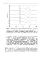
1 4 . 1 .2 Autographic Diagram Method-When a sharp-kneed
stress-strain diagram is obtained by an autographic recording
device, take the stress corresponding to the top of the knee
(Fig. 7), or the stress at which the curve drops as the yield
point.
1 4. 1 .3 Total Extension Under Load Method-When testing
material for yield point and the test specimens may not exhibit
a well-defined disproportionate deformation that characterizes
a yield point as measured by the drop of the beam, halt of the
pointer, or autographic diagram methods described in 1 4. 1 . 1
and 14. 1 .2, a value equivalent to the yield point in its practical
significance may be determined by the following method and
may be recorded as yield point: Attach a Class C or better
extensometer (Notes 5 and 6) to the specimen. When the load
producing a specified extension (Note 7) is reached record the
stress corresponding to the load as the yield point (Fig. 8).
=
5 2 000 psi ( 360 MPa)
(I)
When the offset is 0.2 % or larger, the extensometer used
shall qualify as a Class B2 device over a strain range of 0.05 to
1 .0 %. If a smaller offset is specified, it may be necessary to
specify a more accurate device (that is, a Class B 1 device) or
reduce the lower limit of the strain range (for example, to
0.01 %) or both. See also Note 10 for automatic devices.
NoTE 9-For stress-strain diagrams not containing a distinct modulus,
such as for some cold-worked materials, it is recommended that the
extension under load method be utilized. If the offset method is used for
materials without a distinct modulus, a modulus value appropriate for the
material being tested should be used: 30 000 000 psi (207 000 MPa) for
carbon steel; 29 000 000 psi (200 000 MPa) for ferritic stainless steel;
28 000 000 psi ( 1 93 000 MPa) for austenitic stainless steel. For special
alloys, the producer should be contacted to discuss appropriate modulus
values.
1 4.2.2 Extension Under Load Method-For tests to deter
mine the acceptance or rejection of material whose stress-strain
characteristics are well known from previous tests of similar
material in which stress-strain diagrams were plotted, the total
strain corresponding to the stress at which the specified offset
(see Notes 1 0 and 1 1 ) occurs will be known within satisfactory
limits. The stress on the specimen, when this total strain is
reached, is the value of the yield strength. In recording values
of yield strength obtained by this method, the value of
"extension" specified or used, or both, shall be stated in
parentheses after the term yield strength, for example:
NOTE 5-Automatic devices are available that determine the load at the
specified total extension without plotting a stress-strain curve. Such
devices may be used if their accuracy has been demonstrated. Multiplying
calipers and other such devices are acceptable for use provided their
accuracy has been demonstrated as equivalent to a Class C extensometer.
NoTE 6-Reference should be made to Practice E83.
NOTE 7-For steel with a yield point specified not over 80 000 psi
(550 MPa), an appropriate value is 0.005 in./in. of gauge length. For
values above 80 000 psi, this method is not valid unless the limiting total
extension is increased.
NoTE 8-The shape of the initial portion of an autographically
determined stress-strain (or a load-elongation) curve may be influenced by
numerous factors such as the seating of the specimen in the grips, the
straightening of a specimen bent due to residual stresses, and the rapid
loading permitted in 8 .4.1 . Generally, the aberrations in this portion of the
curve should be ignored when fitting a modulus line, such as that used to
determine the extension-under-load yield, to the curve. In practice, for a
number of reasons, the straight-line portion of the stress-strain curve may
not go through the origin of the stress-strain diagram. In these cases it is
not the origin of the stress-strain diagram, but rather where the straight
line portion of the stress-strain curve, intersects the strain axis that is
pertinent. All offsets and extensions should be calculated from the
intersection of the straight-line portion of the stress-strain curve with the
strain axis, and not necessarily from the origin of the stress-strain diagram.
See also Test Methods E8/E8M, Note 32.
Yield strength (0.5 % EUL)
=
5 2 000 psi (360 MPa)
(2)
The total strain can be obtained satisfactorily b y use of a
Class B 1 extensometer (Note 5 , Note 6, and Note 8) .
NoTE 1 0-Automatic devices are available that determine offset yield
strength without plotting a stress-strain curve. Such devices may be used
if their accuracy has been demonstrated.
NoTE 1 1 -The appropriate magnitude of the extension under load will
obviously vary with the strength range of the particular steel under test. In
general, the value of extension under load applicable to steel at any
strength level may be determined from the sum of the proportional strain
and the plastic strain expected at the specified yield strength. The
following equation is used:
Extension under load, in./in. of gauge length = ( YSI E ) + r
1 4. 2 Yield Strength-Yield strength is the stress at which a
material exhibits a specified limiting deviation from the pro
portionality of stress to strain . The deviation is expressed in
terms of strain, percent offset, total extension under load, and
so forth. Determine yield strength by one of the following
methods:
14.2. 1 Offset Method-To determine the yield strength by
the "offset method," it is necessary to secure data (autographic
or numerical) from which a stress-strain diagram with a distinct
modulus characteristic of the material being tested may be
drawn. Then on the stress-strain diagram (Fig. 9) lay off Om
equal to the specified value of the offset, draw mn parallel to
OA, and thus locate r, the intersection of mn with the
stress-strain curve corresponding to load R, which is the
yield-strength load. In recording values of yield strength
obtained by this method, the value of offset specified or used,
or both, shall be stated in parentheses after the term yield
strength, for example:
(3)
where:
YS
E
r
specified yield strength, psi or MPa,
modulus of elasticity, psi or MPa, and
limiting plastic strain, in./in.
1 4 . 3 Tensile Strength-Calculate the tensile strength by
dividing the maximum load the specimen sustains during a
tension test by the original cross-sectional area of the speci
men. If the upper yield strength is the maximum stress
recorded and if the stress-strain curve resembles that of Test
Methods E8/E8M-1 5a Fig. 25, the maximum stress after
discontinuous yielding shall be reported as the tensile strength
unless otherwise stated by the purchaser.
1 4 .4 Elongation:
1 4 .4. 1 Fit the ends of the fractured specimen together
carefully and measure the distance between the gauge marks to
the nearest 0 . 0 1 in. (0.25 mm) for gauge lengths of 2 in. and
under, and to the nearest 0.5 % of the gauge length for gauge
10
Eqr{tkijv"d{"CUVO"Kpv)n..cm"tkijvu"tgugtxgft�"Vjw"Pqx"39"32<63<73" I OV"4244
Fqypnqcfgfl rtkpvgf"d{
Uj cp i j ck"Ucqvqp i "Wpkxgtukv{.. Uj cp i j ck"Ucqvqp i "Wpkxgtukv{ +"rwtuwcpv"vq"Nkegpug"C i tggogp\IJ"Pq"hwtvj gt"tgrtqfwevkqpu"cwvj qtk 1 gfO
0
A370-22
as a percentage of the original area is the reduction of area.
lengths over 2 in. A percentage scale reading to 0.5 % of the
gauge length may be used. The elongation is the increase in
length of the gauge length, expressed as a percentage of the
original gauge length. In recording elongation values, give both
the percentage increase and the original gauge length.
1 4.4.2 If any part of the fracture takes place outside of the
middle half of the gauge length or in a punched or scribed mark
within the reduced section, the elongation value obtained may
not be representative of the material. If the elongation so
measured meets the minimum requirements specified, no
further testing is indicated, but if the elongation is less than the
minimum requirements, discard the test and retest.
1 4.4.3 Automated tensile testing methods using extensom
eters allow for the measurement of elongation in a method
described below. Elongation may be measured and reported
either this way, or as in the method described above, fitting the
broken ends together. Either result is valid.
1 4 .4.4 Elongation at fracture is defined as the elongation
measured just prior to the sudden decrease in force associated
with fracture. For many ductile materials not exhibiting a
sudden decrease in force, the elongation at fracture can be
taken as the strain measured just prior to when the force falls
below 1 0 % of the maximum force encountered during the test.
1 4.4.4. 1 Elongation at fracture shall include elastic and
plastic elongation and may be determined with autographic or
automated methods using extensometers verified over the
strain range of interest. Use a class B2 or better extensometer
for materials having less than 5 % elongation; a class C or
better extensometer for materials having elongation greater
than or equal to 5 % but less than 50 %; and a class D or better
extensometer for materials having 50 % or greater elongation.
In all cases, the extensometer gauge length shall be the nominal
gauge length required for the specimen being tested. Due to the
lack of precision in fitting fractured ends together, the elonga
tion after fracture using the manual methods of the preceding
paragraphs may differ from the elongation at fracture deter
mined with extensometers.
1 4 .4.4.2 Percent elongation at fracture may be calculated
directly from elongation at fracture data and be reported
instead of percent elongation as calculated in 14.4. 1 . However,
these two parameters are not interchangeable. Use of the
elongation at fracture method generally provides more repeat
able results.
m
o
FIG. 7 Stress-strain Diagram Showing Yield Point Corresponding
With Top of Knee
R -------------------------
o
Strain
�---------------------------�
om
14.5 Reduction of Area-Fit the ends of the fractured
specimen together and measure the mean diameter or the width
and thickness at the smallest cross section to the same accuracy
as the original dimensions. The difference between the area
thus found and the area of the original cross section expressed
n
=
m
Specified Extension Under Load
FIG. 8 Stress-strain Diagram Showing Yield Point or Yield
Strength by Extension Under Load Method
11
Eqr{tkijv"d{"CUVO"Kpv)n""cm"tkijvu"tgugtxgft�"Vjw"Pqx"39"32<63<73" 1 OV"4244
Fqypnqcfgfl rtkpvgf"d{
Uj cp i j ck"Ucqvqp i "Wpkxgtukv{""Uj cp i j ck"Ucqvqp i "Wpkxgtukv{ +"rwtuwcpv"vq"Nkegpug"C i tggogp\IJ"Pq"hwtvj gt"tgrtqfwevkqpu"cwvj qtk 1 gfO
0
R
I
I
I
I
I
I
I
A
A370-22
another or to approximate tensile strength. These conversion
hardness numbers have been obtained using fixed-location
hardness testing machines and computer-generated curves and
are presented to the nearest 0. 1 point to permit accurate
reproduction of those curves. All converted hardness numbers
must be considered approximate. All converted Rockwell and
Vickers hardness numbers shall be rounded to the nearest
whole number.
n
- - - - - - - - - - - - - - - - �- - - - -
/
, r
I
I
I
I
I
I
I
I
I
I
I
I
I
I
I
I
I
I
I
I
I
I
I
I
I
I
I
I
I
I
I
I
I
om
=
I
I
I
I
I
I
I
I
I
1 6.2 Converted Hardness Numbers and Scales:
1 6.2. 1 If the product specification permits alternative hard
ness testing to determine conformance to a specified hardness
requirement, the conversions listed in Tables 2-5 shall be used.
1 6.2.2 When reporting converted hardness numbers and
scales from fixed-location hardness testing machine
measurements, the measured hardness and test scale shall be
indicated in parentheses, for example: 353 HBW (38 HRC).
This means that a hardness number of 38 was obtained using
the Rockwell C scale and converted to a Brinell hardness of
353.
1 6 .2.3 When reporting converted hardness numbers from
portable hardness testing machine measurements, the measured
hardness and test scale shall be indicated in parentheses, as
shown in the examples in Table 6.
Strain
Specified Offset
FIG. 9 Stress-strain Diagram for Determination of Yield Strength
by Offset Method
17. Brinell Hardness Fixed-Location Testing
1 7 . 1 Description:
1 7 . 1 . 1 A specified load is applied to a fiat surface of the
specimen to be tested, through a tungsten carbide ball of
specified diameter. The average diameter of the indentation is
used as a basis for calculation of the Brinell hardness number.
The quotient of the applied load divided by the area of the
surface of the indentation, which is assumed to be spherical, is
termed the Brinell hardness number (HBW) in accordance with
the following equation:
BEND TEST
15. Description
1 5 . 1 The bend test is one method for evaluating ductility,
but it cannot be considered as a quantitative means of predict
ing service performance in all bending operations. The severity
of the bend test is primarily a function of the angle of bend of
the inside diameter to which the specimen is bent, and of the
cross section of the specimen. These conditions are varied
according to location and orientation of the test specimen and
the chemical composition, tensile properties, hardness, type,
and quality of the steel specified. Test Methods E 1 90 and E290
may be consulted for methods of performing the test.
HBW =
P![(nD!2) (D - �) ]
(4)
where:
HBW
p
1 5 . 2 Unless otherwise specified, it shall be permissible to
age bend test specimens. The time-temperature cycle employed
must be such that the effects of previous processing will not be
materially changed. It may be accomplished by aging at room
temperature 24 to 48 h, or in shorter time at moderately
elevated temperatures by boiling in water or by heating in oil
or in an oven.
D
d
Brinell hardness number,
applied load, kgf,
diameter of the tungsten carbide ball, mm, and
average diameter of the indentation, mm.
NoTE 1 2-The Erin ell hardness number from a fixed-location testing
machine is more conveniently secured from standard tables such as Table
7, which show numbers corresponding to the various indentation
diameters, usually in increments of 0.05 mm.
NoTE 1 3-In Test Method E1 0 the values are stated in SI units, whereas
in this section kg/m units are used.
1 5 .3 Bend the test specimen at room temperature to an
inside diameter, as designated by the applicable product
specific ations, to the extent specified. The speed of bending is
ordinarily not an important factor.
1 7 . 1 .2 The standard Brinell hardness fixed-location testing
machine using a 1 0 mm tungsten carbide ball employs a 3000
kgf load for hard materials and a 1 500 or 500 kgf load for thin
sections or soft materials (see Annex A2 on Steel Tubular
Products). Other loads and different size indenters may be used
when specified. In recording hardness values, the diameter of
the ball and the load must be stated except when a 10 mm ball
and 3000 kgf load are used.
17 . 1 .3 A range of hardness can properly be specified only
for quenched and tempered or normalized and tempered
material. For annealed material a maximum figure only should
HARDNESS TEST METHODS
16. General
1 6. 1 A hardness test is a means of determining resistance to
penetration and is occasionally employed to obtain a quick
approximation of tensile strength. Tables 2-5 are for the
conversion of hardness measurements from one scale to
12
Eqr{tkijv"d{"CUVO"Kpv)n..cm"tkijvu"tgugtxgft�"Vjw"Pqx"39"32<63<73" I OV"4244
Fqypnqcfgfl rtkpvgf"d{
Uj cp i j ck"Ucqvqp i "Wpkxgtukv{"'Uj cp i j ck"Ucqvqp i "Wpkxgtukv{ +"rwtuwcpv"vq"Nkegpug"C i tggogp\IJ"Pq"hwtvj gt"tgrtqfwevkqpu"cwvj qtk 1 gfO
0
A370-22
TABLE 2 Approximate Hard ness Conversion Nu mbers for Nonaustenitic SteelsA (Rockwell C to Other Hard ness Numbers)
Rockwell C
Scale, 1 50 kgf
Load,
Diamond
Penetrator
68
67
66
65
64
63
62
61
60
59
58
57
56
55
54
53
52
51
50
49
48
47
46
45
44
43
42
41
40
39
38
37
36
35
34
33
32
31
30
29
28
27
26
25
24
23
22
21
20
Vickers
Hardness
Number
940
900
865
832
BOO
772
746
720
697
674
653
633
613
595
577
560
544
528
513
498
484
471
458
446
434
423
412
402
392
382
372
363
354
345
336
327
318
310
302
294
286
279
272
266
260
254
248
243
238
Brinell
Hardness
3000 kgf Load,
10 mm Ball
Knoop
Hardness,
500 gf Load
and Over
739
722
706
688
670
654
634
615
595
577
560
543
525
512
496
482
468
455
442
432
421
409
400
390
381
371
362
353
344
336
327
319
311
301
294
286
279
271
264
258
253
247
243
237
231
226
920
895
870
846
822
799
776
754
732
71 0
690
670
650
630
612
594
576
558
542
526
51 0
495
480
466
452
438
426
414
402
391
380
370
360
351
342
334
326
31 8
311
304
297
290
284
278
272
266
261
256
251
Rockwell A
Scale, 60 kgf
Load,
Diamond
Penetrator
85.6
85.0
84.5
83.9
83.4
82.8
82.3
81 .8
81 .2
80.7
80. 1
79.6
79.0
78.5
78.0
77.4
76.8
76.3
75.9
75.2
74.7
74.1
73.6
73. 1
72.5
72.0
71 .5
70.9
70.4
69.9
69.4
68.9
68.4
67.9
67.4
66.8
66.3
65.8
65.3
64.6
64.3
63.8
63.3
62.8
62.4
62.0
61 .5
61 .0
60.5
1 5N Scale, 1 5
kgf Load,
Diamond
Penetrator
93.2
92.9
92.5
92.2
91 .8
91 .4
91 . 1
90.7
90.2
89.8
89.3
88.9
88.3
87.9
87.4
86.9
86.4
85.9
85.5
85.0
84.5
83.9
83.5
83.0
82.5
82.0
81 .5
80.9
80.4
79.9
79.4
78.8
78.3
77.7
77.2
76.6
76.1
75.6
75.0
74.5
73.9
73.3
72.8
72.2
71 .6
71 .0
70.5
69.9
69.4
Rockwell Superficial Hardness
30N Scale 30
45N Scale, 45
kgf Load,
kgf Load,
Diamond
Diamond
Penetrator
Penetrator
84.4
75.4
74.2
83.6
82.8
73.3
8 1 .9
72.0
81.1
71 .0
80. 1
69.9
79.3
68.8
78.4
67.7
66.6
77.5
76.6
65.5
64.3
75.7
74.8
63.2
73.9
62.0
73.0
60.9
72.0
59.8
7 1 .2
58.6
70.2
57.4
56.1
69.4
68.5
55.0
67.6
53.8
52.5
66.7
65.8
51 .4
64.8
50.3
49.0
64.0
63. 1
47.8
62.2
46.7
6 1 .3
45.5
60.4
44.3
43.1
59.5
41 .9
58.6
40.8
57.7
56.8
39.6
55.9
38.4
55.0
37.2
36.1
54.2
34.9
53.3
52. 1
33.7
5 1 .3
32.5
31 .3
50.4
30.1
49.5
48.6
28.9
47.7
27.8
26.7
46.8
45.9
25.5
45.0
24.3
23.1
44.0
43.2
22.0
42.3
20.7
41 .5
1 9.6
Approximate
Tensile
Strength, ksi
( MPa)
351 (2420)
338 (2330)
325 (2240)
31 3 (21 60)
301 (2070)
292 (2010)
283 ( 1 950)
273 ( 1 880)
264 ( 1 820)
255 ( 1 760)
246 ( 1 700)
238 ( 1 640)
229 ( 1 580)
221 ( 1 520)
21 5 ( 1 480)
208 ( 1 430)
201 ( 1 390)
1 94 ( 1 340)
1 88 ( 1 300)
1 82 ( 1 250)
1 77 ( 1 220)
1 71 ( 1 1 80)
1 66 ( 1 1 40)
1 61 ( 1 1 1 0)
1 56 ( 1 080)
1 52 ( 1 050)
1 49 ( 1 030)
1 46 ( 1 01 0)
1 41 (970)
1 38 (950)
1 35 (930)
1 31 (900)
1 28 (880)
1 25 (860)
1 23 (850)
1 1 9 (820)
1 1 7 (81 0)
1 1 5 (790)
1 1 2 (770)
1 1 0 (760)
A This table gives the approximate interrelationships of hardness numbers and approximate tensile strength of steels. It is possible that steels of various compositions and
processing histories will deviate in hardness-tensile strength relationship from the data presented in this table. The data in this table should not be used for austenitic
stainless steels, but have been shown to be applicable for ferritic and martensitic stainless steels. The data in this table should not be used to establish a relationship
between hardness numbers and tensile strength of hard drawn wire. The data in this table was developed using fixed-location hardness testing machines. Where more
precise conversions are required, they should be developed specially for each steel composition, heat treatment, and part. Caution should be exercised if conversions from
this table are used for the acceptance or rejection of product. The approximate interrelationships may affect acceptance or rejection.
be specified. For normalized material a minimum or a maxi
mum hardness may be specified by agreement. In general, no
hardness requirements should be applied to untreated material.
1 7. 1 .4 Brinell hardness may be required when tensile prop
erties are not specified.
1 7 .2. 1 Testing Machine-A Brinell hardness fixed-location
testing machine is acceptable for use over a loading range
within which its load measuring device is accurate to :±: 1 %.
17 .2.2 Measuring Microscope-The divisions of the mi
crometer scale of the microscope or other measuring devices
used for the measurement of the diameter of the indentations
1 7.2 Appa ratus-Equipment shall meet the following re
quirements:
13
Eqr{tkijv"d{"CUVO"Kpv)n"'cm"tkijvu"tgugtxgft�"Vjw"Pqx"39"32<63<73" 1 OV"4244
Fqypnqcfgfl rtkpvgf"d{
Uj cp i j ck"Ucqvqp i "Wpkxgtukv{"'Uj cp i j ck"Ucqvqp i "Wpkxgtukv{ +"rwtuwcpv"vq"Nkegpug"C i tggogp\IJ"Pq"hwtvj gt"tgrtqfwevkqpu"cwvj qtk 1 gfO
0
A370-22
TABLE 3 Approximate Hard ness Conversion Nu mbers for Nonaustenitic SteelsA (Rockwell B to Other Hard ness Numbers)
Rockwell B
Scale, 1 00
kgf Load 1/16in.
(1 .588 mm)
Ball
1 00
99
98
97
96
95
94
93
92
91
90
89
88
87
86
85
84
83
82
81
80
79
78
77
76
75
74
73
72
71
70
69
68
67
66
65
64
63
62
61
60
59
58
57
56
55
54
53
52
51
50
49
48
47
46
45
44
43
42
41
40
39
38
37
36
35
34
33
32
Rockwell Superficial Hardness
Vickers
Hardness
Number
Brinell
Hardness, 300
kgf Load, 1 0
m m Ball
Knoop
Hardness,
500 gf Load &
Over
Rockwell A
Scale, 60 kgf
Load, Diamond
Penetrator
240
234
228
222
216
21 0
205
200
1 95
1 90
1 85
1 80
1 76
1 72
1 69
1 65
1 62
1 59
1 56
1 53
1 50
1 47
1 44
141
1 39
1 37
1 35
1 32
1 30
1 27
1 25
1 23
121
119
117
116
114
112
110
1 08
1 07
1 06
1 04
1 03
1 01
1 00
240
234
228
222
216
210
205
200
1 95
1 90
1 85
1 80
1 76
1 72
1 69
1 65
1 62
1 59
1 56
1 53
1 50
1 47
1 44
141
1 39
1 37
1 35
1 32
1 30
1 27
1 25
1 23
121
119
117
116
114
112
110
1 08
1 07
1 06
1 04
1 03
1 01
1 00
251
246
241
236
231
226
221
216
211
206
201
1 96
1 92
1 88
1 84
1 80
1 76
1 73
1 70
1 67
1 64
1 61
1 58
1 55
1 52
1 50
1 47
1 45
1 43
141
1 39
1 37
1 35
1 33
1 31
1 29
1 27
1 25
1 24
1 22
1 20
118
117
115
114
112
111
110
1 09
1 08
1 07
1 06
1 05
1 04
1 03
1 02
1 01
1 00
99
98
97
96
95
94
93
92
91
90
89
61 .5
60.9
60.2
59.5
58.9
58.3
57.6
57.0
56.4
55.8
55.2
54.6
54.0
53.4
52.8
52.3
51 . 7
51.1
50.6
50.0
49.5
48.9
48.4
47.9
47.3
46.8
46.3
45.8
45.3
44.8
44.3
43.8
43.3
42.8
42.3
41 .8
41 .4
40.9
40.4
40.0
39.5
39.0
38.6
38.1
37.7
37.2
36.8
36.3
35.9
35.5
35.0
34.6
34.1
33.7
33.3
32.9
32.4
32.0
3 1 .6
3 1 .2
30.7
30.3
29.9
29.5
29. 1
28.7
28.2
27.8
27.4
14
Rockwell F
Scale, 60 kgf
Load, '116-in.
( 1 .588 mm) Ball
99.6
99. 1
98.5
98.0
97.4
96.8
96.2
95.6
95. 1
94.5
93.9
93.4
92.8
92.2
91 . 7
91 . 1
90.5
90.0
89.4
88.8
88.2
87.7
87. 1
86.5
86.0
85.4
84.8
84.3
83.7
83. 1
82.6
82.0
81 .4
80.8
80.3
79.7
79. 1
78.6
78.0
77.4
76.9
76.3
75.7
75.2
Eqr{tkijv"d{"CUVO"Kpv)n..cm"tkijvu"tgugtxgft�"Vjw"Pqx"39"32<63<73" 1 OV"4244
Fqypnqcfgfl rtkpvgf"d{
Uj cp i j ck"Ucqvqp i "Wpkxgtukv{.. Uj cp i j ck"Ucqvqp i "Wpkxgtukv{ +"rwtuwcpv"vq"Nkegpug"C i tggogp\IJ"Pq"hwtvj gt"tgrtqfwevkqpu"cwvj qtk 1 gfO
1 5T Scale,
15 kgf
Load, 1/16in.
( 1 .588 mm)
Ball
30T Scale,
30 kgf
Load, 1/1 6in.
( 1 .588 mm)
Ball
45T Scale,
45 kgf
Load, 1/1 6in.
(1 .588 mm)
Ball
93.1
92.8
92.5
92.1
91 .8
91 .5
91 .2
90.8
90.5
90.2
89.9
89.5
89.2
88.9
88.6
88.2
87.9
87.6
87.3
86.9
86.6
86.3
86.0
85.6
85.3
85.0
84.7
84.3
84.0
83.7
83.4
83.0
82.7
82.4
82.1
81 .8
81 .4
81 . 1
80.8
80.5
80.1
79.8
79.5
79.2
78.8
78.5
78.2
77.9
77.5
77.2
76.9
76.6
76.2
75.9
75.6
75.3
74.9
74.6
74.3
74.0
73.6
73.3
73.0
72.7
72.3
72.0
71 .7
71 .4
71 .0
83.1
82.5
81 .8
81 . 1
80.4
79.8
79.1
78.4
77.8
77.1
76.4
75.8
75.1
74.4
73.8
73.1
72.4
71 .8
71 . 1
70.4
69.7
69.1
68.4
67.7
67.1
66.4
65.7
65.1
64.4
63.7
63.1
62.4
61 .7
61 .0
60.4
59.7
59.0
58.4
57.7
57.0
56.4
55.7
55.0
54.4
53.7
53.0
52.4
51 . 7
51 .0
50.3
49.7
49.0
48.3
47.7
47.0
46.3
45.7
45.0
44.3
43.7
43.0
42.3
41 .6
41 .0
40.3
39.6
39.0
38.3
37.6
72.9
71 .9
70.9
69.9
68.9
67.9
66.9
65.9
64.8
63.8
62.8
61 .8
60.8
59.8
58.8
57.8
56.8
55.8
54.8
53.8
52.8
51 .8
50.8
49.8
48.8
47.8
46.8
45.8
44.8
43.8
42.8
41 .8
40.8
39.8
38.7
37.7
36.7
35.7
34.7
33.7
32.7
31 . 7
30.7
29.7
28.7
27.7
26.7
25.7
24.7
23.7
22.7
21 .7
20.7
1 9.7
1 8.7
1 7.7
1 6.7
1 5.7
1 4.7
1 3.6
1 2.6
1 1 .6
1 0.6
9.6
8.6
7.6
6.6
5.6
4.6
Approximate
Tensile
Strength ksi
(M Pa)
116
114
1 09
1 04
1 02
1 00
98
94
92
90
89
88
86
84
83
82
81
80
77
73
72
70
69
68
67
66
65
64
63
62
61
60
59
58
57
56
(BOO)
(785)
(750)
(71 5)
(705)
(690)
(675)
(650)
(635)
(620)
(61 5)
(605)
(590)
(580)
(570)
(565)
(560)
(550)
(530)
(505)
(495)
(485)
(475)
(470)
(460)
(455)
(450)
(440)
(435)
(425)
(420)
(41 5)
(405)
(400)
(395)
(385)
0
A370-22
TABLE 3
Continued
Rockwell Superficial Hardness
Rockwell B
Scale, 1 00
kgf Load 1/16·
in.
(1 .588 mm)
Ball
Vickers
Hardness
Number
Brinell
Hardness, 300
kgf Load, 1 0
m m Ball
Knoop
Hardness,
500 gf Load &
Over
88
87
31
30
Rockwell A
Scale, 60 kgf
Load, Diamond
Penetrator
Rockwell F
Scale, 60 kgf
Load, '116-in.
( 1 .588 mm) Ball
1 5T Scale,
15 kgf
Load, 1/16·
in.
( 1 .588 mm)
Ball
27.0
26.6
74.6
74.0
70.7
70.4
30T Scale,
30 kgf
Load, 1/1 6·
in.
( 1 .588 mm)
Ball
37.0
36.3
45T Scale,
45 kgf
Load, 1/1 6·
in.
(1 .588 mm)
Ball
Approximate
Tensile
Strength ksi
(M Pa)
3.6
2.6
A This table gives the approximate interrelationships of hardness numbers and approximate tensile strength of steels. It is possible that steels of various compositions and
processing histories will deviate in hardness-tensile strength relationship from the data presented in this table. The data in this table should not be used for austenitic
stainless steels, but have been shown to be applicable for ferritic and martensitic stainless steels. The data in this table should not be used to establish a relationship
between hardness numbers and tensile strength of hard drawn wire. The data in this table was developed using fixed-location hardness testing machines. Where more
precise conversions are required, they should be developed specially for each steel composition, heat treatment, and part.
TABLE 4 Approximate Hardness Conversion Numbers for Austenitic Steels (Rockwell C to other Hardness Numbers)
Rockwell C Scale, 1 50 kgf
Load, Diamond Penetrator
Rockwell A Scale, 60 kgf
Load, Diamond Penetrator
48
47
46
45
44
43
42
41
40
39
38
37
36
35
34
33
32
31
30
29
28
27
26
25
24
23
22
21
20
74.4
73.9
73.4
72.9
72.4
71 .9
71 .4
70.9
70.4
69.9
69.3
68.8
68.3
67.8
67.3
66.8
66.3
65.8
65.3
64.8
64.3
63.8
63.3
62.8
62.3
61 .8
61 .3
60.8
60.3
Rockwell Superficial Hardness
1 5N Scale, 1 5 kgf Load,
Diamond Penetrator
30N Scale, 30 kgf Load,
Diamond Penetrator
45N Scale, 45 kgf Load,
Diamond Penetrator
84.1
83.6
83.1
82.6
82.1
81 .6
81 .0
80.5
80.0
79.5
79.0
78.5
78.0
77.5
77.0
76.5
75.9
75.4
74.9
74.4
73.9
73.4
72.9
72.4
71 .9
71 .3
70.8
70.3
69.8
66.2
65.3
64.5
63.6
62.7
61 .8
61 .0
60.1
59.2
58.4
57.5
56.6
55.7
54.9
54.0
53.1
52.3
51 .4
50.5
49.6
48.8
47.9
47.0
46.2
45.3
44.4
43.5
42.7
41 .8
52.1
50.9
49.8
48.7
47.5
46.4
45.2
44.1
43.0
41 .8
40.7
39.6
38.4
37.3
36.1
35.0
33.9
32.7
31 .6
30.4
29.3
28.2
27.0
25.9
24.8
23.6
22.5
21 .3
20.2
1 7 . 3 Test Specimen-Brinell hardness indentations are made
on prepared areas and sufficient metal must be removed from
the surface to eliminate decarburized metal and other surface
irregularities. The thickness of the piece tested must be such
that no bulge or other marking showing the effect of the load
appears on the side of the piece opposite the indentation.
shall be such as to permit the direct measurement of the
diameter to 0. 1 mm and the estimation of the diameter to
0.05 mm.
NOTE 1 4-This requirement applies to the construction of the micro
scope only and is not a requirement for measurement of the indentation,
see 17 .4.4.
1 7 .2.3 Standard Ball-The standard tungsten carbide ball
for Brinell hardness fixed-location testing machine is 1 0 mm
(0.3937 in.) in diameter with a deviation from this value of not
more than 0.005 mm (0.0002 in.) in any diameter. A tungsten
carbide ball suitable for use must not show a permanent change
in diameter greater than 0.0 1 mm (0.0004 in.) when pressed
with a force of 3000 kgf against the test specimen. Steel ball
indenters are no longer permitted for use in Brinell hardness
fixed-location testing machines in accordance with these test
methods.
1 7 .4 Test Procedure:
1 7 .4. 1 Detailed Test Procedure-For detailed requirements
of the test procedure, reference shall be made to the latest
revision of Test Method E l O for fixed-location hardness testing
machines.
1 7 .4.2 It is essential that the applicable product specifica
tions state clearly the position at which Brinell hardness
indentations are to be made and the number of such indenta
tions required. The distance of the center of the indentation
15
Eqr{tkijv"d{"CUVO"Kpv)n..cm"tkijvu"tgugtxgft�"Vjw"Pqx"39"32<63<73" 1 OV"4244
Fqypnqcfgfl rtkpvgf"d{
Uj cp i j ck"Ucqvqp i "Wpkxgtukv{.. Uj cp i j ck"Ucqvqp i "Wpkxgtukv{ +"rwtuwcpv"vq"Nkegpug"C i tggogp\IJ"Pq"hwtvj gt"tgrtqfwevkqpu"cwvj qtk 1 gfO
0
A370-22
TABLE 5 Approximate Hardness Conversion Numbers for Austenitic Steels (Rockwell B to other Hardness Numbers)
Rockwell Superficial Hardness
Rockwell B
Scale, 1 00 kg! Load,
1/16in. (1 .588 mm) Ball
Brinell Indentation
Diameter, m m
Brinell Hardness,
3000 kg! Load,
10 mm Ball
Rockwell A Scale,
60 kg! Load,
Diamond Penetrator
1 00
99
98
97
96
95
94
93
92
91
90
89
88
87
86
85
84
83
82
81
80
3.79
3.85
3.91
3.96
4.02
4.08
4. 1 4
4.20
4.24
4.30
4.35
4.40
4.45
4.51
4.55
4.60
4.65
4.70
4.74
4.79
4.84
256
248
240
233
226
21 9
21 3
207
202
1 97
1 92
1 87
1 83
1 78
1 74
1 70
1 67
1 63
1 60
1 56
1 53
61 .5
60.9
60.3
59.7
59. 1
58.5
58.0
57.4
56.8
56.2
55.6
55.0
54.5
53.9
53.3
52.7
52. 1
51 .5
50.9
50.4
49.8
1 5T Scale,
1 5 kg! Load,
'116-in. ( 1 .588 mm) Ball
30T Scale,
30 kg! Load,
1/16-in. ( 1 .588 mm)
Ball
45T Scale,
45 kg! Load,
1/16-in. ( 1 .588 mm) Ball
91 . 5
91 .2
90.8
90.4
90. 1
89.7
89.3
88.9
88.6
88.2
87.8
87.5
87. 1
86.7
86.4
86.0
85.6
85.2
84.9
84.5
84.1
80.4
79.7
79.0
78.3
77.7
77.0
76.3
75.6
74.9
74.2
73.5
72.8
72.1
71 .4
70.7
70.0
69.3
68.6
67.9
67.2
66.5
70.2
69.2
68.2
67.2
66.1
65. 1
64.1
63. 1
62. 1
61 . 1
60.1
59.0
58.0
57.0
56.0
55.0
54.0
52.9
51 .9
50.9
49.9
TABLE 6 Reporting Converted Hardness Numbers and Scales from Portable Hardness Tests
NOTE 1-Since the data in the hardness conversion tables in this standard were developed using fixed-location hardness testing machines, the use of
these tables to convert portable hardness testing numbers may have a larger approximation range than for converting fixed-location hardness testing
numbers.
Portable Hardness Test Method
A833
A956/A956M
A 1 038
E110
Converted Hardness Number and
Scale
38 H RC
38 H RC
38 H RC
38 H RC
Portable Hardness Test Number and
Scale
353 H BC/340
353 HB (HLD)
372 HV (UCI}
353 HBW/P
from the edge of the specimen or edge of another indentation
must be at least two and one-half times the diameter of the
indentation.
1 7.4.3 Apply the load for 1 0 to 15 s .
1 7 .4.4 Measure diameters o f the indentation in accordance
with Test Method E 1 0.
1 7 .4.5 The Brinell hardness fixed-location testing machine
is not recommended for materials above 650 HBW.
1 7 .4.5 . 1 If a ball is used in a test of a specimen which shows
a Brinell hardness number greater than the limit for the ball as
detailed in 1 7 .4.5, the ball shall be either discarded and
replaced with a new ball or remeasured to ensure conformance
with the requirements of Test Method E 1 0.
Reported Converted Hardness Number and Scale
38 HRC (353 HBC/340)
38 HRC (353 HB (HLD))
38 HRC {372 HV (UCI)}
38 HRC (353 HBW/P)
1 7 .5. 1 .4 The only exception to the above requirement is for
the HBW 1 0/3000 scale when a 1 0 to 1 5 s dwell time is used.
Only in the case of this one Brinell hardness scale may the
designation be reported simply as HBW.
1 7 . 5 . 1 .5 Examples: 220 HBW = Brinell hardness of 220
determined with a ball of 1 0 mm diameter and with a test force
of 3000 kgf applied for 1 0 to 1 5 s; 350 HBW 511 500 = Brinell
hardness of 350 determined with a ball of 5 mm diameter and
with a test force of 1 500 kgf applied for 1 0 to 1 5 s.
18. Rockwell Fixed-Location Hardness Testing
1 8 . 1 Description:
1 8 . 1 . 1 In this test a hardness number is obtained by deter
mining the depth of penetration of a diamond point or a
tungsten carbide ball into the specimen using a fixed-location
hardness testing machine. A minor load of 1 0 kgf is first
applied which causes an initial penetration, sets the penetrator
on the material and holds it in position. A major load which
depends on the scale being used is applied increasing the depth
of indentation. The major load is removed and, with the minor
load still acting, the Rockwell number, which is proportional to
the difference in penetration between the major and minor
loads is determined; this is usually done by the machine and
shows on a dial, digital display, printer, or other device. This is
1 7.5 Reporting Brinell Hardness Numbers:
1 7 . 5 . 1 Brinell hardness numbers shall not be reported by a
number alone because it is necessary to indicate which indenter
and force has been employed in making the test. Reported
Brinell hardness numbers shall always be followed by the scale
symbol HBW, and be supplemented by an index indicating the
test conditions in the following order:
1 7. 5 . 1 . 1 Diameter of the ball, mm,
1 7.5 . 1 .2 A value representing the applied load, kgf, and,
1 7.5. 1 .3 The applied force dwell time, s, if other than 10 to
1 5 s.
16
Eqr{tkijv"d{"CUVO"Kpv)n..cm"tkijvu"tgugtxgft�"Vjw"Pqx"39"32<63<73" 1 OV"4244
Fqypnqcfgfl rtkpvgf"d{
Uj cp i j ck"Ucqvqp i "Wpkxgtukv{.. Uj cp i j ck"Ucqvqp i "Wpkxgtukv{ +"rwtuwcpv"vq"Nkegpug"C i tggogp\IJ"Pq"hwtvj gt"tgrtqfwevkqpu"cwvj qtk 1 gfO
0
A370-22
TABLE 7 Brinell Hardness NumbersA
(Ball 1 0 mm in Diameter, Applied Loads of 500, 1 500, and 3000 kgf)
Diameter
of Indenta
tion, mm
2.00
2.01
2.02
2.03
2.04
2.05
2.06
2.07
2.08
2.09
2.1 0
2.11
2.1 2
2.1 3
2.1 4
2.1 5
2.16
2.1 7
2.1 8
2.1 9
2.20
2.21
2.22
2.23
2.24
2.25
2.26
2.27
2.28
2.29
2.30
2.31
2.32
2.33
2.34
2.35
2.36
2.37
2.38
2.39
2.40
2.41
2.42
2.43
2.44
2.45
2.46
2.47
2.48
2.49
2.50
2.51
2.52
2.53
2.54
2.55
2.56
2.57
2.58
2.59
2.60
2.61
2.62
2.63
2.64
2.65
2.66
2.67
2.68
2.69
Brinell Hardness
Number
500kgf
Load
1 500kgf
Load
3000kg!
Load
158
473
945
156
468
936
154
463
926
153
459
917
151
454
908
150
450
899
148
445
890
147
441
882
146
437
873
144
432
865
143
428
856
14 1
424
848
140
420
840
139
416
832
137
4 12
824
136
408
817
135
404
809
134
401
802
132
397
794
131
393
787
130
390
780
129
386
772
128
383
765
126
379
758
125
376
752
124
372
745
123
369
738
122
366
732
121
363
725
120
359
719
119
356
712
118
353
706
117
350
700
116
347
694
115
344
688
114
34 1
682
113
338
676
1 12
335
670
111
332
665
110
330
659
109
327
653
108
324
648
107
322
643
106
319
637
105
316
632
104
313
627
104
311
621
103
308
616
102
306
611
101
303
606
1 00
99.4
98.6
97.8
97.1
96.3
95.5
94.8
94.0
93.3
92.6
91 .8
91 . 1
90.4
89.7
89.0
88.4
87.7
87.0
86.4
301
298
296
294
291
289
287
284
282
280
278
276
273
271
269
267
265
263
261
259
601
597
592
587
582
578
573
569
564
560
555
551
547
543
538
534
530
526
522
518
Diameter
of
Indenta
tion, mm
3.25
3.26
3.27
3.28
3.29
3.30
3.31
3.32
3.33
3.34
3.35
3.36
3.37
3.38
3.39
3.40
3.41
3.42
3.43
3.44
3.45
3.46
3.47
3.48
3.49
3.50
3.51
3.52
3.53
3.54
3.55
3.56
3.57
3.58
3.59
3.60
3.61
3.62
3.63
3.64
3.65
3.66
3.67
3.68
3.69
3.70
3.71
3.72
3.73
3.74
3.75
3.76
3.77
3.78
3.79
3.80
3.81
3.82
3.83
3.84
3.85
3.86
3.87
3.88
3.89
3.90
3.91
3.92
3.93
3.94
Brinell Hardness
Number
500kgf
Load
1 500kg!
Load
3000kg!
Load
58.6
58.3
57.9
57.5
57.2
56.8
56.5
56. 1
55.8
55.4
55. 1
54.8
54.4
54. 1
53.8
53.4
53. 1
52.8
52.5
52.2
51 .8
51 .5
51 .2
50.9
50.6
50.3
50.0
49.7
49.4
49.2
48.9
48.6
48.3
48.0
47.7
47.5
47.2
46.9
46.7
46.4
46. 1
45.9
45.6
45.4
45. 1
44.9
44.6
44.4
44. 1
43.9
43.6
43.4
43. 1
42.9
42.7
42.4
42.2
42.0
41 .7
41 .5
41 .3
41 . 1
40.9
40.6
40.4
40.2
40.0
39.8
39.6
39.4
1 76
1 75
1 74
1 73
1 72
1 70
1 69
1 68
1 67
1 66
1 65
1 64
1 63
1 62
1 61
1 60
1 59
1 58
1 57
1 56
1 56
1 55
1 54
1 53
1 52
1 51
1 50
1 49
1 48
1 47
1 47
1 46
1 45
1 44
1 43
1 42
1 42
141
1 40
1 39
1 38
1 38
1 37
1 36
1 35
1 35
1 34
1 33
1 32
1 32
1 31
1 30
1 29
1 29
1 28
1 27
1 27
1 26
1 25
1 25
1 24
1 23
1 23
1 22
121
1 21
1 20
119
119
118
352
350
347
345
343
341
339
337
335
333
331
329
326
325
323
321
319
317
315
313
311
309
307
306
304
302
300
298
297
295
293
292
290
288
286
285
283
282
280
278
277
275
274
272
271
269
268
266
265
263
262
260
259
257
256
255
253
252
250
249
248
246
245
244
242
241
240
239
237
236
Diameter
of
Indenta
tion, mm
4.50
4.51
4.52
4.53
4.54
4.55
4.56
4.57
4.58
4.59
4.60
4.61
4.62
4.63
4.64
4.65
4.66
4.67
4.68
4.69
4.70
4.71
4.72
4.73
4.74
4.75
4.76
4.77
4.78
4.79
4.80
4.81
4.82
4.83
4.84
4.85
4.86
4.87
4.88
4.89
4.90
4.91
4.92
4.93
4.94
4.95
4.96
4.97
4.98
4.99
5.00
5.01
5.02
5.03
5.04
5.05
5.06
5.07
5.08
5.09
5. 1 0
5.11
5. 1 2
5. 1 3
5.14
5. 1 5
5.16
5. 1 7
5. 1 8
5. 1 9
17
Brinell Hardness
Number
500kgf
Load
1 500kgf
Load
3000kg!
Load
29.8
29.6
29.5
29.3
29.2
29.1
28.9
28.8
28.7
28.5
28.4
28.3
28.1
28.0
27.9
27.8
27.6
27.5
27.4
27.3
27.1
27.0
26.9
26.8
26.6
26.5
26.4
26.3
26.2
26.1
25.9
25.8
25.7
25.6
25.5
25.4
25.3
25.1
25.0
24.9
24.8
24.7
24.6
24.5
24.4
24.3
24.2
24.1
24.0
23.9
23.8
23.7
23.6
23.5
23.4
23.3
23.2
23.1
23.0
22.9
22.8
22.7
22.6
22.5
22.4
22.3
22.2
22.1
22.0
21 .9
89.3
88.8
88.4
88.0
87.6
87.2
86.8
86.4
86.0
85.6
85.4
84.8
84.4
84.0
83.6
83.3
82.9
82.5
82. 1
81 .8
81 .4
81 .0
80.7
80.3
79.9
79.6
79.2
78.9
78.5
78.2
77.8
77.5
77. 1
76.8
76.4
76.1
75.8
75.4
75. 1
74.8
74.4
74.1
73.8
73.5
73.2
72.8
72.5
72.2
71 .9
71 .6
71 .3
71 .0
70.7
70.4
70. 1
69.8
69.5
69.2
68.9
68.6
68.3
68.0
67.7
67.4
67. 1
66.9
66.6
66.3
66.0
65.8
1 79
1 78
1 77
1 76
1 75
1 74
1 74
1 73
1 72
1 71
1 70
1 70
1 69
1 68
1 67
1 67
1 66
1 65
1 64
1 64
1 63
1 62
161
161
1 60
1 59
1 58
1 58
1 57
1 56
1 56
1 55
1 54
1 54
1 53
1 52
1 52
151
1 50
1 50
1 49
1 48
1 48
1 47
1 46
1 46
1 45
1 44
1 44
1 43
1 43
1 42
141
141
1 40
1 40
1 39
1 38
1 38
1 37
1 37
1 36
1 35
1 35
1 34
1 34
1 33
1 33
1 32
1 32
Eqr{tkijv"d{"CUVO"Kpv)n..cm"tkijvu"tgugtxgft�"Vjw"Pqx"39"32<63<73" 1 OV"4244
Fqypnqcfgfl rtkpvgf"d{
Uj cp i j ck"Ucqvqp i "Wpkxgtukv{.. Uj cp i j ck"Ucqvqp i "Wpkxgtukv{ +"rwtuwcpv"vq"Nkegpug"C i tggogp\IJ"Pq"hwtvj gt"tgrtqfwevkqpu"cwvj qtk 1 gfO
Diameter
of
Indenta
tion, mm
5.75
5.76
5.77
5.78
5.79
5.80
5.81
5.82
5.83
5.84
5.85
5.86
5.87
5.88
5.89
5.90
5.91
5.92
5.93
5.94
5.95
5.96
5.97
5.98
5.99
6.00
6.01
6.02
6.03
6.04
6.05
6.06
6.07
6.08
6.09
6.10
6.11
6.12
6.13
6.14
6.15
6.16
6.17
6.18
6.19
6.20
6.21
6.22
6.23
6.24
6.25
6.26
6.27
6.28
6.29
6.30
6.31
6.32
6.33
6.34
6.35
6.36
6.37
6.38
6.39
6.40
6.41
6.42
6.43
6.44
Brinell Hardness
Number
500kgf
Load
1 500kgf
Load
3000kgf
Load
1 7.5
1 7.4
1 7.4
1 7.3
1 7.2
1 7.2
1 7. 1
1 7.0
1 7.0
1 6.9
1 6.8
1 6.8
1 6.7
1 6.7
1 6.6
1 6.5
1 6.5
1 6.4
1 6.3
1 6.3
1 6.2
1 6.2
16.1
1 6.0
1 6.0
14.0
52.5
52.3
52.1
51 .9
51 .7
51 .5
51 .3
51 . 1
50.9
50.7
50.5
50.3
50.2
50.0
49.8
49.6
49.4
49.2
49.0
48.8
48.7
48.5
48.3
48.1
47.9
47.7
47.6
47.4
47.2
47.0
46.8
46.7
46.5
46.3
46.2
46.0
45.8
45.7
45.5
45.3
45.2
45.0
44.8
44.7
44.5
44.3
44.2
44.0
43.8
43.7
43.5
43.4
43.2
43.1
42.9
42.7
42.6
42.4
42.3
42.1
1 05
1 05
1 04
1 04
1 03
1 03
1 03
1 02
1 02
1 01
1 01
1 01
1 00
99.9
99.5
99.2
98.8
98.4
98.0
97.7
97.3
96.9
96.6
96.2
95.9
95.5
95.1
94.8
94.4
94. 1
93.7
93.4
93.0
92.7
92.3
92.0
9 1 .7
9 1 .3
9 1 .0
90.6
90.3
90.0
89.6
89.3
89.0
88.7
88.3
88.0
87.7
87.4
87.1
86.7
86.4
86.1
85.8
85.5
85.2
84.9
84.6
84.3
14.0
42.0
84.0
13.9
41.8
83. 7
13.9
41.7
83.4
13.8
4 1.5
83. 1
13.8
41.4
82.8
13. 7
4 1.2
82.5
13. 7
41. 1
82.2
13.6
40.9
81.9
13.6
40.8
81.6
13.5
40.6
81.3
15.9
15.9
15.8
15. 7
15. 7
15.6
15.6
15.5
15.4
15.4
15.3
15.3
15.2
15.2
15. 1
15. 1
15.0
14.9
14.9
14.8
14. 7
14. 7
14. 7
14.6
14.6
14.5
14.5
14.4
14.4
14.3
14.2
14.2
14. 1
14. 1
0
A370-22
TABLE 7
Diameter
of Indenta
tion, mm
2.70
2.71
2.72
2.73
2.74
2.75
2.76
2.77
2.78
2.79
2.80
2.81
2.82
2.83
2.84
2.85
2.86
2.87
2.88
2.89
2.90
2.91
2.92
2.93
2.94
2.95
2.96
2.97
2.98
2.99
3.00
3.01
3.02
3.03
3.04
3.05
3.06
3.07
3.08
3.09
3. 1 0
3. 1 1
3. 1 2
3. 1 3
3. 1 4
3. 1 5
3. 1 6
3. 1 7
3. 1 8
3. 1 9
3.20
3.21
3.22
3.23
3.24
A
Brinell Hardness
Number
500kgf
Load
1 500kgf
Load
3000kgf
Load
85.7
85.1
84.4
83.8
83.2
82.6
81 .9
81 .3
80.8
80.2
79.6
79.0
78.4
77.9
77.3
76.8
76.2
75.7
75.1
74.6
74.1
73.6
73.0
72.5
72.0
71 .5
71 .0
70.5
70.1
69.6
69.1
68.6
68.2
67.7
67.3
66.8
66.4
65.9
65.5
65.0
64.6
64.2
63.8
63.3
62.9
62.5
62.1
61 .7
61 .3
60.9
60.5
60.1
59.8
59.4
59.0
257
255
253
251
250
248
246
244
242
240
239
237
235
234
232
230
229
227
225
224
222
221
219
218
216
215
213
212
210
209
207
206
205
203
202
200
1 99
1 98
1 96
1 95
1 94
1 93
191
1 90
1 89
1 88
1 86
1 85
1 84
1 83
1 82
1 80
1 79
1 78
1 77
514
510
507
503
499
495
492
488
485
481
477
474
471
467
464
461
457
454
451
448
444
441
438
435
432
429
426
423
420
417
415
412
409
406
404
401
398
395
393
390
388
385
383
380
378
375
373
370
368
366
363
361
359
356
354
Diameter
of
Indenta
tion, mm
3.95
3.96
3.97
3.98
3.99
4.00
4.01
4.02
4.03
4.04
4.05
4.06
4.07
4.08
4.09
4.1 0
4.11
4.12
4.1 3
4.14
4.1 5
4.16
4.1 7
4.1 8
4.1 9
4.20
4.21
4.22
4.23
4.24
4.25
4.26
4.27
4.28
4.29
4.30
4.31
4.32
4.33
4.34
4.35
4.36
4.37
4.38
4.39
4.40
4.41
4.42
4.43
4.44
4.45
4.46
4.47
4.48
4.49
Continued
Brinell Hardness
Number
500kgf
Load
1 500kgf
Load
3000kg!
Load
39. 1
38.9
38.7
38.5
38.3
38. 1
37.9
37.7
37.5
37.3
37. 1
37.0
36.8
36.6
36.4
36.2
36.0
35.8
35.7
35.5
35.3
35. 1
34.9
34.8
34.6
34.4
34.2
34. 1
33.9
33.7
33.6
33.4
33.2
33. 1
32.9
32.8
32.6
32.4
32.3
32. 1
32.0
31 .8
31 .7
31 . 5
31 .4
31 .2
31 . 1
30.9
30.8
30.6
30.5
30.3
30.2
30.0
29.9
117
117
116
116
115
114
114
113
113
112
111
111
110
110
1 09
1 09
1 08
1 08
1 07
1 06
1 06
1 05
1 05
1 04
1 04
1 03
1 03
1 02
1 02
1 01
1 01
1 00
99.7
99.2
98.8
98.3
97.8
97.3
96.8
96.4
95.9
95.5
95.0
94.5
94.1
93.6
93.2
92.7
92.3
91 .8
91 .4
91 .0
90.5
90.1
89.7
235
234
232
231
230
229
228
226
225
224
223
222
221
219
218
217
216
215
214
213
212
211
210
209
208
207
205
204
203
202
201
200
1 99
1 98
1 98
1 97
1 96
1 95
1 94
1 93
1 92
1 91
1 90
1 89
1 88
1 87
1 86
1 85
1 85
1 84
1 83
1 82
1 81
1 80
1 79
Diameter
of
Indenta
tion, mm
5.20
5.21
5.22
5.23
5.24
5.25
5.26
5.27
5.28
5.29
5.30
5.31
5.32
5.33
5.34
5.35
5.36
5.37
5.38
5.39
5.40
5.41
5.42
5.43
5.44
5.45
5.46
5.47
5.48
5.49
5.50
5.51
5.52
5.53
5.54
5.55
5.56
5.57
5.58
5.59
5.60
5.61
5.62
5.63
5.64
5.65
5.66
5.67
5.68
5.69
5.70
5.71
5.72
5.73
5.74
Brinell Hardness
Number
500kgf
Load
1 500kgf
Load
3000kg!
Load
21 .8
21 .7
21 .6
21 .6
21 .5
21 .4
21 .3
21 .2
21 . 1
21 .0
20.9
20.9
20.8
20.7
20.6
20.5
20.4
20.3
20.3
20.2
20.1
20.0
1 9.9
1 9.9
1 9.8
1 9.7
1 9.6
1 9.5
1 9.5
1 9.4
1 9.3
1 9.2
1 9.2
1 9. 1
1 9.0
1 8.9
1 8.9
1 8.8
1 8.7
1 8.6
1 8.6
1 8.5
1 8.4
1 8.3
1 8.3
1 8.2
1 8. 1
1 8. 1
1 8.0
1 7.9
1 7.8
1 7.8
1 7.7
1 7.6
1 7.6
65.5
65.2
64.9
64.7
64.4
64.1
63.9
63.6
63.3
63. 1
62.8
62.6
62.3
62. 1
61 .8
61 .5
61 .3
61 .0
60.8
60.6
60.3
60. 1
59.8
59.6
59.3
59. 1
58.9
58.6
58.4
58.2
57.9
57.7
57.5
57.2
57.0
56.8
56.6
56.3
56. 1
55.9
55.7
55.5
55.2
55.0
54.8
54.6
54.4
54.2
54.0
53.7
53.5
53.3
53. 1
52.9
52.7
1 31
1 30
1 30
1 29
1 29
1 28
1 28
1 27
1 27
1 26
1 26
1 25
1 25
1 24
1 24
1 23
1 23
1 22
1 22
121
121
1 20
1 20
119
119
118
118
117
117
116
116
115
115
114
114
114
113
113
112
112
111
111
110
110
110
1 09
1 09
1 08
1 08
1 07
1 07
1 07
1 06
1 06
1 05
Prepared by the Engineering Mechanics Section, Institute for Standards Technology.
18
Eqr{tkijv"d{"CUVO"Kpv)n..cm"tkijvu"tgugtxgft�"Vjw"Pqx"39"32<63<73" 1 OV"4244
Fqypnqcfgfl rtkpvgf"d{
Uj cp i j ck"Ucqvqp i "Wpkxgtukv{.. Uj cp i j ck"Ucqvqp i "Wpkxgtukv{ +"rwtuwcpv"vq"Nkegpug"C i tggogp\IJ"Pq"hwtvj gt"tgrtqfwevkqpu"cwvj qtk 1 gfO
Diameter
of
Indenta
tion, mm
6.45
6.46
6.47
6.48
6.49
6.50
6.51
6.52
6.53
6.54
6.55
6.56
6.57
6.58
6.59
6.60
6.61
6.62
6.63
6.64
6.65
6.66
6.67
6.68
6.69
6.70
6.71
6.72
6.73
6.74
6.75
6.76
6.77
6.78
6.79
6.80
6.81
6.82
6.83
6.84
6.85
6.86
6.87
6.88
6.89
6.90
6.91
6.92
6.93
6.94
6.95
6.96
6.97
6.98
6.99
Brinell Hardness
Number
500kgf
Load
1 500kgf
Load
3000kgf
Load
13.5
40.5
81.0
13.4
40.4
80. 7
13.4
40.2
80.4
13.4
40. 1
80. 1
13.3
39.9
79.8
13.3
39.8
79. 6
13.2
39.6
79.3
13.2
39.5
79. 0
13. 1
39.4
78. 7
13. 1
39.2
78.4
13.0
39. 1
78.2
13.0
38.9
78. 0
12.9
38.8
77. 6
12.9
38. 7
77.3
12.8
38.5
77. 1
12.8
38.4
76.8
12.8
38.3
76.5
12. 7
38. 1
76.2
12. 7
38.0
76. 0
12. 6
37.9
75. 7
12. 6
37. 7
75.4
12.5
37.6
75.2
12.5
37.5
74. 9
12.4
37.3
74. 7
12.4
37.2
74.4
12.4
37. 1
74. 1
12.3
36.9
73.9
12.3
36.8
73. 6
12.2
36. 7
73.4
12.2
36.6
73. 1
12. 1
36.4
72. 8
12. 1
36.3
72. 6
12. 1
36.2
72.3
12. 0
36.0
72. 1
12. 0
1 1. 9
35. 9
71.8
35.8
71.6
11.9
35. 7
71.3
11.8
35.5
71. 1
1 1. 8
35.4
70.8
11.8
35. 3
70. 6
11.7
35.2
70.4
11.7
35. 1
70. 1
11.6
34.9
69.9
11.6
34.8
69.6
11.6
34. 7
69.4
11.5
34.6
69.2
11.5
34.5
68.9
1 1.4
34.3
68. 7
11.4
34.2
68.4
11.4
34. 1
68.2
11.3
34.0
68.0
11.3
33. 9
67.7
11.3
33.8
67.5
1 1.2
33.6
67.3
1 1.2
33. 5
67.0
0
A370-22
bar hardness to indicate that i t was determined b y a portable
comparative hardness tester, as in the following example:
1 9 . 1 .2. 1 232 HBC/240, where 232 is the hardness test result
using the portable comparative test method (HBC) and 240 is
the B rinell hardness of the comparative test bar.
1 9 . 1 .3 Test Method A956/A956M:
1 9 . 1 .3 . 1 The measured hardness number shall be reported in
accordance with the standard methods and appended with a
Leeb impact device in parenthesis to indicate that it was
determined by a portable hardness tester, as in the following
example:
( 1) 350 HLD where 350 is the hardness test result using the
portable Leeb hardness test method with the HLD impact
device.
1 9 . 1 .3.2 When hardness values converted from the Leeb
number are reported, the portable instrument used shall be
reported in parentheses, for example:
(1) 350 HB (HLD) where the original hardness test was
performed using the portable Leeb hardness test method with
the HLD impact device and converted to the Brinell hardness
value (HB).
1 9 . 1 .4 Test Method A 1 038-The measured hardness number
shall be reported in accordance with the standard methods and
appended with UCI in parenthesis to indicate that it was
determined by a portable hardness tester, as in the following
example:
1 9. 1 .4. 1 446 HV (UCI) 10 where 446 is the hardness test
result using the portable UCI test method under a force of
1 0 kgf.
1 9 . 1 .5 Test Method EllO-The measured hardness number
shall be reported in accordance with the standard methods and
appended with a /P to indicate that it was determined by a
portable hardness testing machine and shall reference Test
Method E l l O, as follows:
1 9 . 1 .5 . 1 Rockwell Hardness Examples:
( 1) 40 HRC/P where 40 is the hardness test result using the
Rockwell C portable test method.
(2) 72 HRBW/P where 72 is the hardness test result using
the Rockwell B portable test method using a tungsten carbide
ball indenter.
1 9 . 1 .5.2 Brinell Hardness Examples:
(1) 220 HBWIP 10/3000 where 220 is the hardness test
result using the Brinell portable test method with a ball of
1 0 mm diameter and with a test force of 3000 kgf (29.42 kN)
applied for 1 0 to 1 5 s.
(2) 350 HBW/P 51750 where 350 is the hardness test result
using the Brinell portable test method with a ball of 5 mm
diameter and with a test force of 750 kgf (7.355 kN) applied for
1 0 to 1 5 s.
an arbitrary number which increases with increasing hardness.
The scales most frequently used are as follows :
Penetrator
B
c
1/• s-in. tungsten carbide ball
Diamond brale
1 00
1 50
10
10
1 8. 1 .2 Rockwell superficial fixed-location hardness testing
machines are used for the testing of very thin steel or thin
surface layers. Loads of 1 5 , 30, or 45 kgf are applied on a
tungsten carbide (or a hardened steel) ball or diamond
penetrator, to cover the same range of hardness values as for
the heavier loads. Use of a hardened steel ball i s permitted only
for testing thin sheet tin mill products as found in Specifica
tions A623 and A623M using HR 1 5T and HR30T scales with
a diamond spot anvil. (Testing of this product using a tungsten
carbide indenter may give significantly different results as
compared to historical test data obtained using a hardened steel
ball.) The superficial hardness scales are as follows:
Scale
Symbol
Penetrator
Major
Load. kgf
Minor
Load. kgf
1 5T
30T
45T
1 5N
30N
45N
'/•s-in. tungsten carbide or steel ball
1/win. tungsten carbide or steel ball
'/•s-in. tungsten carbide ball
Diamond brale
Diamond brale
Diamond brale
15
30
45
15
30
45
3
3
3
3
3
3
1 8.2 Reporting Rockwell Hardness Numbers:
1 8.2. 1 Rockwell hardness numbers shall not be reported by
a number alone because it is necessary to indicate which
indenter and force has been employed in making the test.
Reported Rockwell hardness numbers shall always be followed
by the scale symbol, for example: 96 HRBW, 40 HRC, 75
HR 1 5N, 56 HR30TS, or 77 HR30TW. The suffix W indicates
use of a tungsten carbide ball. The suffix S indicates use of a
hardened steel ball as permitted in 1 8 . 1 .2.
1 8.3 Test Blocks-Machines should be checked to make
certain they are in good order by means of standardized
Rockwell test blocks.
1 8.4 Detailed Test Procedure-For detailed requirements of
the test procedure, reference shall be made to the latest revision
of Test Methods E 1 8 for fixed-location hardness testing ma
chines.
19. Portable Hardness Testing
1 9 . 1 Although this standard generally prefers the use of
Brinell or Rockwell fixed-location hardness testing machines,
it is not always possible to perform the hardness test using such
equipment due to the part size, location, or other logistical
reasons. In this event, hardness testing using portable equip
ment as described in Test Methods A833, A956/A956M,
A 1 03 8, and E l l O shall be used with strict compliance for
reporting the test results in accordance with the selected
standard (see examples below).
CHARPY IMPACT TESTING
20. Summary
20. 1 A Charpy V-notch impact test is a dynamic test in
which a notched specimen is struck and broken by a single
blow in a specially designed testing machine. The measured
test values may be the energy absorbed, the percentage shear
fracture, the lateral expansion opposite the notch, or a combi
nation thereof.
1 9. 1 . 1 Reporting Portable Hardness Numbers:
1 9. 1 .2 Test Method A833-The measured hardness number
shall be reported in accordance with the standard methods and
given the HBC designation followed by the comparative test
19
Eqr{tkijv"d{"CUVO"Kpvln..cm"tkijvu"tgugtxgft�"Vjw"Pqx"39"32<63<73" I OV"4244
Fqypnqcfgfl rtkpvgf"d{
Uj cp i j ck"Ucqvqp i "Wpkxgtukv{"'Uj cp i j ck"Ucqvqp i "Wpkxgtukv{ +"rwtuwcpv"vq"Nkegpug"C i tggogp\IJ"Pq"hwtvj gt"tgrtqfwevkqpu"cwvj qtk 1 gfO
0
A370-22
20.2 Testing temperatures other than room (ambient) tem
perature often are specified in product or general requirement
specifications (hereinafter referred to as the specification).
Although the testing temperature is sometimes related to the
expected service temperature, the two temperatures need not be
identical.
Methods E23). The linear velocity at the point of impact should
be in the range of 1 6 to 19 ft/s (4.9 to 5 . 8 m/s) .
NoTE 1 5-An investigation o f striker radius effect i s available.6
22.2 Temperature Media:
22.2. 1 For testing at other than room temperature, it is
necessary to condition the Charpy specimens in media at
controlled temperatures.
22.2.2 Low temperature media usually are chilled fluids
(such as water, ice plus water, dry ice plus organic solvents, or
liquid nitrogen) or chilled gases.
22.2.3 Elevated temperature media are usually heated liq
uids such as mineral or silicone oils. Circulating air ovens may
be used.
21. Significance and Use
2 1 . 1 Ductile Versus Brittle Behavior-Body-centered-cubic
or ferritic alloys exhibit a significant transition in behavior
when impact tested over a range of temperatures. At tempera
tures above transition, impact specimens fracture by a ductile
(usually rnicrovoid coalescence) mechanism, absorbing rela
tively large amounts of energy. At lower temperatures, they
fracture in a brittle (usually cleavage) manner absorbing
appreciably less energy. Within the transition range, the frac
ture will generally be a mixture of areas of ductile fracture and
brittle fracture.
22.3 Handling Equipment-Tongs, especially adapted to fit
the notch in the impact specimen, normally are used for
removing the specimens from the medium and placing them on
the anvil (refer to Test Methods E23). In cases where the
machine fixture does not provide for automatic centering of the
test specimen, the tongs may be precision machined to provide
centering.
2 1 .2 The temperature range of the transition from one type
of behavior to the other varies according to the material being
tested. This transition behavior may be defined in various ways
for specification purposes.
2 1 .2. 1 The specification may require a minimum test result
for absorbed energy, fracture appearance, lateral expansion, or
a combination thereof, at a specified test temperature.
2 1 .2.2 The specification may require the determination of
the transition temperature at which either the absorbed energy
or fracture appearance attains a specified level when testing is
performed over a range of temperatures. Alternatively the
specification may require the determination of the fracture
appearance transition temperature (FATTn) as the temperature
at which the required minimum percentage of shear fracture (n)
is obtained.
23. Sampling and Number of Specimens
8-mm rad (0.315")
SPECIMEN
2 1 .3 Further information on the significance of impact
testing appears in Annex AS .
22. Apparatus
-t--Y--- Center of
Strike (W/2)
,__.,,..._....__,_,
.__
22. 1 Testing Machines:
22. 1 . 1 A Charpy impact machine is one in which a notched
specimen is broken by a single blow of a freely swinging
pendulum. The pendulum is released from a fixed height. Since
the height to which the pendulum is raised prior to its swing,
and the mass of the pendulum are known, the energy of the
blow is predetermined. A means is provided to indicate the
energy absorbed in breaking the specimen.
22. 1 .2 The other principal feature of the machine is a fixture
(see Fig. 1 0) designed to support a test specimen as a simple
beam at a precise location. The fixture is arranged so that the
notched face of the specimen is vertical. The pendulum strikes
the other vertical face directly opposite the notch. The dimen
sions of the specimen supports and striking edge shall conform
to Fig. 1 0.
22. 1 .3 Charpy machines used for testing steel generally
have capacities in the 220 to 300 ft·lbf (300 to 400 J) energy
range. Sometimes machines of lesser capacity are used;
however, the capacity of the machine should be substantially in
excess of the absorbed energy of the specimens (see Test
Specimen
Support
All dimensional tolerances shall be ±0.05 mm (0.002 in.) unless otherwise
specified.
NoTE 1 -A shall be parallel to B within 2: 1 000 and coplanar with B
within 0.05 mm (0.002 in.).
NoTE 2-C shall be parallel to D within 20: 1 000 and coplanar with D
within 0. 1 25 mm (0.005 in.).
NOTE 3-Finish on unmarked parts shall be 4 J.!ffi ( 1 25 J.!in.).
NoTE 4-Tolerance for the striker corner radius shall be -0.05 mm
(0.002 in.)/+0.50 mm (0.020 in.)
FIG. 10 Charpy (Simple-beam) Impact Test
23 . 1 Sampling:
6 Supporting data have been filed at ASTM International Headquarters and may
be obtained by requesting Research Report RR:AO l - 1 00 1 . Contact ASTM Customer
Service at
20
Eqr{tkijv"d{"CUVO"Kpv)n..cm"tkijvu"tgugtxgft�"Vjw"Pqx"39"32<63<73" I OV"4244
Fqypnqcfgfl rtkpvgf"d{
Uj cp i j ck"Ucqvqp i "Wpkxgtukv{"'Uj cp i j ck"Ucqvqp i "Wpkxgtukv{ +"rwtuwcpv"vq"Nkegpug"C i tggogp\IJ"Pq"hwtvj gt"tgrtqfwevkqpu"cwvj qtk 1 gfO
0
A370-22
( 1 ) Standard size specimens and subsize specimens may
contain the original OD surface of the tubular product as shown
in Fig. 1 2. All other dimensions shall comply with the
requirements of Fig. 1 1 .
23. 1 . 1 Test location and orientation should be addressed by
the specifications. If not, for wrought products, the test location
shall be the same as that for the tensile specimen and the
orientation shall be longitudinal with the notch perpendicular
to the major surface of the product being tested.
23 . 1 .2 Number of Specimens.
23 . 1 .2 . 1 All specimens used for a Charpy impact test shall
be taken from a single test coupon or test location.
23 . 1 .2.2 When the specification calls for a minimum aver
age test result, three specimens shall be tested.
23 . 1 .2.3 When the specification requires determination of a
transition temperature, eight to twelve specimens are usually
needed.
NOTE 1 6-For materials with toughness levels in excess of about
50 ft-lbs, specimens containing the original OD surface may yield values
in excess of those resulting from the use of conventional Charpy
specimens.
23.2.2.3 If a standard full-size specimen cannot be prepared,
the largest feasible standard subsize specimen shall be pre
pared. The specimens shall be machined so that the specimen
does not include material nearer to the surface than 0.020 in.
(0.5 mm).
23.2.2.4 Tolerances for standard subsize specimens are
shown in Fig. 1 1 . Standard subsize test specimen sizes are:
1 0 x 7 . 5 mm, 1 0 x 6.7 mm, 1 0 x 5 mm, 1 0 x 3 . 3 mm, and
1 0 x 2.5 mm.
23.2.2.5 Notch the narrow face of the standard subsize
specimens so that the notch is perpendicular to the 1 0 mm wide
face.
23.2 Type and Size:
23.2. 1 Use a standard full size Charpy V-notch specimen as
shown in Fig. 1 1 , except as allowed in 23.2.2.
23.2.2 Subsized Specimens.
23 .2.2 . 1 For flat material less than 7/16 in. ( 1 1 mm) thick, or
when the absorbed energy is expected to exceed 80 % of full
scale, use standard subsize test specimens.
23.2.2.2 For tubular materials tested in the transverse
direction, where the relationship between diameter and wall
thickness does not permit a standard full size specimen, use
standard subsize test specimens or standard size specimens
containing outer diameter (OD) curvature as follows:
1-g
o•
I '
iii
I
0 2 mm
I
I
l
h(2.165
55 mm _______]
1n.)�
� mm
10 mm
(0.079 in.)
24. Calibration
24. 1 Accuracy and Sensitivity-Calibrate and adjust Charpy
impact machines in accordance with the requirements of Test
Methods E23 .
0. 25
(0.010 in.) rad.
r1 "'[_
_ l..:..:J .f"(o.394 in.)
:
l41o
(0.394mmin.)
L
23.3 Notch Preparation-The machining (for example,
milling, broaching, or grinding) of the notch is critical, as
minor deviations in both notch radius and profile, or tool marks
at the bottom of the notch may result in variations in test data,
particularly in materials with low-impact energy absorption.
(see Annex AS) .
45•
•
25. Conditioning-Temperature Control
NoTE ! -Permissible variations shall be as follows:
25 . 1 When a specific test temperature is required by the
specification or purchaser, control the temperature of the
heating or cooling medium within ::!::: 2 °F ( 1 °C).
90 ±2°
go• ± 10 min
±0.075 mm (±0.003 in.)
+ 0, - 2.5 m m ( + 0, - 0 . 1 00 in.)
±1 m m (±0.039 in.)
±1 0
±0.025 mm (±0.001 in.)
±0.025 mm (±0.001 in.)
2 �m (63 �in.) on notched surface and
opposite face; 4 �m ( 1 25 �in.) on other
two surfaces
Notch length to edge
Adjacent sides shall be at
Cross-section dimensions
Length of specimen (L)
Centering of notch (U2)
Angle of notch
Radius of notch
Notch depth
Finish requirements
NoTE 1 7-For some steels there may not be a need for this restricted
temperature, for example, austenitic steels.
NoTE I S-Because the temperature of a testing laboratory often varies
from 60 to 90 °F ( 1 5 to 32 °C) a test conducted at "room temperature"
might be conducted at any temperature in this range.
26. Procedure
(a) Standard Full Size Specimen
!
y Tl q
\r�; �
lO mm
(0. 394 in.)
f
. 9
1._
L
m
02
\:}}
�
mm
3o
n
IJ
mm (0.079 in.)
�5
\:.j-
\r �
� �264 �
mm
[]
197
.7 mm
[]
o
\rg.5 mm
�2 5 intl-
26. 1 Temperature:
26. 1 . 1 Condition the specimens to be broken by holding
them in the medium at test temperature for at least 5 min in
liquid media and 30 min in gaseous media.
26. 1 .2 Prior to each test, maintain the tongs for handling test
specimens at the same temperature as the specimen so as not to
affect the temperature at the notch.
D
9
26.2 Positioning and Breaking Specimens:
26.2. 1 Carefully center the test specimen in the anvil and
release the pendulum to break the specimen.
26.2.2 If the pendulum is not released within 5 s after
removing the specimen from the conditioning medium, do not
break the specimen. Return the specimen to the conditioning
medium for the period required in 26. 1 . 1 .
NoTE 2-0n subsize specimens, all dimensions and tolerances of the
standard specimen remain constant with the exception of the width, which
varies as shown above and for which the tolerance shall be ± 1 %.
(b)
FIG. 11
Standard Subsize Specimens
Charpy (Simple Beam) Impact Test Specimens
21
Eqr{tkijv'd{"CUVO"Kpv)n..cm"tkijvu"tgugtxgft�"Vjw"Pqx"39"32<63<73" I OV"4244
Fqypnqcfgfl rtkpvgf"d{
Uj cp i j ck"Ucqvqp i "Wpkxgtukv{"'Uj cp i j ck"Ucqvqp i "Wpkxgtukv{ +"rwtuwcpv"vq"Nkegpug"C i tggogp\IJ"Pq"hwtvj gt"tgrtqfwevkqpu"cwvj qtk 1 gfO
0
Dimension
A
B
T
t
A370-22
Description
Reauiremeot
Machined Surface
Original 00 Surface
Specimen Thickness
End Thickness
28 mm Minimum
13.5 mm Maximum
Figure 1 1
112 T Minimum
FIG. 1 2 Tubular Impact Specimen Containing Original OD Surface
26.3 Recovering Specimens-In the event that fracture ap
pearance or lateral expansion must be determined, recover the
matched pieces of each broken specimen before breaking the
next specimen.
26.4.3 .2 Examine each specimen half to ascertain that the
protrusions have not been damaged by contacting the anvil,
machine mounting surface, and so forth. Discard such samples
since they may cause erroneous readings.
26.4.3 . 3 Check the sides of the specimens perpendicular to
the notch to ensure that no burrs were formed on the sides
during impact testing. If burrs exist, remove them carefully by
rubbing on emery cloth or similar abrasive surface, making
sure that the protrusions being measured are not rubbed during
the removal of the burr.
26.4.3.4 Measure the amount of expansion on each side of
each half relative to the plane defined by the undeformed
portion of the side of the specimen using a gauge similar to that
shown in Figs. 1 6 and 1 7.
26.4.3 . 5 Since the fracture path seldom bisects the point of
maximum expansion on both sides of a specimen, the sum of
the larger values measured for each side is the value of the test.
Arrange the halves of one specimen so that compression sides
are facing each other. Using the gauge, measure the protrusion
on each half specimen, ensuring that the same side of the
specimen is measured. Measure the two broken halves indi
vidually. Repeat the procedure to measure the protrusions on
the opposite side of the specimen halves. The larger of the two
values for each side is the expansion of that side of the
specimen.
26.4.3.6 Measure the individual lateral expansion values to
the nearest mil (0.025 mm) and record the values.
26.4.3.7 With the exception described as follows, any speci
men that does not separate into two pieces when struck by a
26.4 Individual Test Values:
26.4. 1 Impact Energy-Record the impact energy absorbed
to the nearest ft·lbf (J).
26.4.2 Fracture Appearance:
26.4.2 . 1 Determine the percentage of shear fracture area by
any of the following methods:
( 1) Measure the length and width of the brittle portion of
the fracture surface, as shown in Fig. 1 3 and determine the
percent shear area from either Table 8 or Table 9 depending on
the units of measurement.
(2) Compare the appearance of the fracture of the specimen
with a fracture appearance chart as shown in Fig. 1 4.
(3) Magnify the fracture surface and compare it to a
precalibrated overlay chart or measure the percent shear
fracture area by means of a planimeter.
(4) Photograph the fractured surface at a suitable magnifi
cation and measure the percent shear fracture area by means of
a planimeter.
26.4.2.2 Determine the individual fracture appearance val
ues to the nearest 5 % shear fracture and record the value.
26.4.3 Lateral Expansion:
26.4.3 . 1 Lateral expansion is the increase in specimen
width, measured in thousandths of an inch (mils), on the
compression side, opposite the notch of the fractured Charpy
V-notch specimen as shown in Fig. 1 5.
Notch
---i7:�����:};2J____:l
Cleavage Area
(shiny)
NoTE 1-Measure average dimensions A and B to the nearest 0.02 in. or 0.5
NoTE 2-Determine the percent shear fracture using Table 8 or Table 9.
nun.
FIG. 1 3 Determination of Percent Shear Fracture
22
Eqr{tkijv"d{"CUVO"Kpv)n..cm"tkijvu"tgugtxgft�"Vjw"Pqx"39"32<63<73" 1 OV"4244
Fqypnqcfgfl rtkpvgf"d{
Uj cp i j ck"Ucqvqp i "Wpkxgtukv{.. Uj cp i j ck"Ucqvqp i "Wpkxgtukv{ +"rwtuwcpv"vq"Nkegpug"C i tggogp\IJ"Pq"hwtvj gt"tgrtqfwevkqpu"cwvj qtk 1 gfO
0
A370-22
TABLE 8 Percent Shear for Measurements Made in Inches
NOTE 1-Since this table is set up for finite measurements or dimensions A and 8, 1 00 % shear is to be reported when either A or 8 is zero.
Dimension
8, in.
0.05
0.10
0.12
0.14
0.16
0.18
0.20
0.22
Dimension
0.24
0.26
0.28
0.30
0.32
0.34
0.36
0.38
0.40
0.05
0.1 0
0.12
0.14
0.1 6
0.1 8
0.20
0.22
0.24
0.26
0.28
0.30
0.31
98
96
95
94
94
93
92
91
90
90
89
88
88
96
92
90
89
87
85
84
82
81
79
77
76
75
95
90
88
86
85
83
81
79
77
75
73
71
70
94
89
86
84
82
80
77
75
73
71
68
66
65
94
87
85
82
79
77
74
72
69
67
64
61
60
93
85
83
80
77
74
72
68
65
62
59
56
55
92
84
81
77
74
72
68
65
61
58
55
52
50
91
82
79
75
72
68
65
61
57
54
50
47
45
90
81
77
73
69
65
61
57
54
50
46
42
40
90
79
75
71
67
62
58
54
50
46
41
37
35
89
77
73
68
64
59
55
50
46
41
37
32
30
88
76
71
66
61
56
52
47
42
37
32
27
25
87
74
69
64
59
54
48
43
38
33
28
23
20
86
73
67
62
56
51
45
40
34
29
23
18
18
85
71
65
59
53
48
42
36
30
25
18
13
10
85
69
63
57
51
45
39
33
27
20
14
9
5
84
68
61
55
48
42
36
29
23
16
10
3
0
A,
in.
TABLE 9 Percent Shear for Measurements Made in M i l l imetres
NoTE 1 -Since this table is set up for finite measurements or dimensions A and 8, I 00 % shear is to be reported when either A or 8 is zero.
Dimension
A,
mm
Dimension
8, mm
1 .0
1 .5
2.0
2.5
3.0
3.5
4.0
4.5
5.0
5.5
6.0
6.5
7.0
7.5
8.0
8.5
9.0
9.5
10
1 .0
1 .5
2.0
2.5
3.0
3.5
4.0
4.5
5.0
5.5
6.0
6.5
7.0
7.5
8.0
99
98
98
97
96
96
95
94
94
93
92
92
91
91
90
98
97
96
95
94
93
92
92
91
90
89
88
87
86
85
98
96
95
94
92
91
90
89
88
86
85
84
82
81
80
97
95
94
92
91
89
88
86
85
83
81
80
78
77
75
96
94
92
91
89
87
85
83
81
79
77
76
74
72
70
96
93
91
89
87
85
82
80
78
76
74
72
69
67
65
95
92
90
88
85
82
80
77
75
72
70
67
65
62
60
94
92
89
86
83
80
77
75
72
69
66
63
61
58
55
94
91
88
84
81
78
75
72
69
66
62
59
56
53
50
93
90
86
83
79
76
72
69
66
62
59
55
52
48
45
92
89
85
81
77
74
70
66
62
59
55
51
47
44
40
92
88
84
80
76
72
67
63
59
55
51
47
43
39
35
91
87
82
78
74
69
65
61
56
52
47
43
39
34
30
91
86
81
77
72
67
62
58
53
48
44
39
34
30
25
90
85
80
75
70
65
60
55
50
45
40
35
30
25
20
89
84
79
73
68
63
57
52
47
42
36
31
26
20
15
89
83
77
72
66
61
55
49
44
38
33
27
21
16
10
88
82
76
70
64
58
52
46
41
35
29
23
17
11
5
88
81
75
69
62
56
50
44
37
31
25
19
12
6
0
(a) Shear Fracture Appearance Charts
D D D EJ Ei Ei Ei Ei i:i
10
20
30
40
50
60
70
80
90
(b) Guide for Estimating Shear Fracture Appearance
FIG. 1 4 Fracture Appearance Charts and Percent Shear Fracture Comparator
single blow shall be reported as unbroken. The lateral expan
sion of an unbroken specimen can be reported as broken if the
specimen can be separated by pushing the hinged halves
together once and then pulling them apart without further
23
Eqr{tkijv"d{"CUVO"Kpv)n""cm"tkijvu"tgugtxgft�"Vjw"Pqx"39"32<63<73" 1 OV"4244
Fqypnqcfgfl rtkpvgf"d{
Uj cp i j ck"Ucqvqp i "Wpkxgtukv{""Uj cp i j ck"Ucqvqp i "Wpkxgtukv{ +"rwtuwcpv"vq"Nkegpug"C i tggogp\IJ"Pq"hwtvj gt"tgrtqfwevkqpu"cwvj qtk 1 gfO
0
A370-22
A
FIG. 1 5 Halves of Broken Charpy V-notch Impact Specimen Joined for Measurement of Lateral Expansion, Dimension A
FIG. 1 6 Lateral Expansion Gauge for Charpy I m pact Specimens
24
Eqr{tkijv"d{"CUVO"Kpv)n""cm"tkijvu"tgugtxgft�"Vjw"Pqx"39"32<63<73" I OV"4244
Fqypnqcfgfl rtkpvgf"d{
Uj cp i j ck"Ucqvqp i "Wpkxgtukv{""Uj cp i j ck"Ucqvqp i "Wpkxgtukv{ +"rwtuwcpv"vq"Nkegpug"C i tggogp\IJ"Pq"hwtvj gt"tgrtqfwevkqpu"cwvj qtk 1 gfO
0
�
A370-22
�M a-
so
�1-'-25
r - - - -
!
----·
"'
....
...
�I
lI
� �
I
I
I
I
I
I
I
I
�I
SEE DETAIL B
..;
��
4
I
"11
"11
'--'----
"'
M �
-�-L----·
2
,...---
- -- --
1.7
I
I
I
4
2
6
I
2
3
s
I
I
I
BILL OF MATERIAL
��o?Nl 4
DESCRIPTION
BASE PlATE
X
5/8
1/2
7 x 4 x 3/4
6·1/4 X 3·1/2 X 1/16
SCR��m"ET
SCRt%.0�ET
PAD
X
DIAL INDICATOR
MATERIAL AND SIZE
STEEL SAE
STEEL SAE
1015·1020
1015·1020
RUBBER
1/4·20 X I" L.G.
1/4-20 x 3/4" L.G.
(SEE NOTE 2)
STEEL
STEEL
3.S
6.25
PAD Q)
....
"'
...
NOTE: THESE SURFACES TO BE ON SAME
-- PLANE - LAP AT ASSEMBLY
2
��
��fi'""'
.31
.62
DETAIL B (ENLARGED)
NOTES:
1.) FLASH CHROME PLATE ITEMS 1 & 2
2.) DIAL INDICATOR- STARRETT NO. 25-241
RANGE .001 - .250
� (IYP)
AFTER ASS'Y. OF ITEMS &
CEMENT
RUBBER PAD (ITEM 3) TO BASE
1 2,
DRILL
BACK • ADJUSTABLE BRACKET
CONTACT POINT
(.437) DIA.
N0.2
FIG. 1 7 Assembly and Details for Lateral Expansion Gauge
fatiguing the specimen, and the lateral expansion measured for
the unbroken specimen (prior to bending) is equal to or greater
than that measured for the separated halves. In the case where
a specimen cannot be separated into two halves, the lateral
expansion can be measured as long as the shear lips can be
accessed without interference from the hinged ligament that
has been deformed during testing.
specimens shall be equal to or greater than the specified
minimum average value.
27.2 Test Specifying a Minimum Transition Temperature:
27 .2. 1 Determination of Transition Temperature:
27 . 2. 1 . 1 Break one specimen at each of a series of tempera
tures above and below the anticipated transition temperature
using the procedures in Section 26. Record each test tempera
ture to the nearest 1 °F (0.5 °C).
27. Interpretation of Test Result
27.2. 1 .2 Plot the individual test results (ft·lbf or percent
shear) as the ordinate versus the corresponding test temperature
as the abscissa and construct a best-fit curve through the plotted
data points.
27. 1 When the acceptance criterion of any impact test is
specified to be a minimum average value at a given
temperature, the test result shall be the average (arithmetic
mean rounded to the nearest ft-lbf (J)) of the individual test
values of three specimens from one test location.
27 . 1 . 1 When a minimum average test result is specified:
27 . 1 . 1 . 1 The test result is acceptable when all of the below
are met:
( 1) The test result equals or exceeds the specified minimum
average (given in the specification),
(2) The individual test value for not more than one speci
men measures less than the specified minimum average, and
(3) The individual test value for any specimen measures
not less than two-thirds of the specified minimum average.
27 . 1 . 1 .2 If the acceptance requirements of 27 . 1 . 1 . 1 are not
met, perform one retest of three additional specimens from the
same test location. Each individual test value of the retested
27 . 2. 1 .3 If transition temperature is specified as the tem
perature at which a test value is achieved, determine the
temperature at which the plotted curve intersects the specified
test value by graphical interpolation (extrapolation is not
permitted). Record this transition temperature to the nearest
5 °F (3 °C). If the tabulated test results clearly indicate a
transition temperature lower than specified, it is not necessary
to plot the data. Report the lowest test temperature for which
test value exceeds the specified value.
27 . 2. 1 .4 Accept the test result if the determined transition
temperature is equal to or lower than the specified value.
27 . 2. 1 .5 If the determined transition temperature is higher
than the specified value, but not more than 20 °F ( 1 2 °C) higher
25
Eqr{tkijv"d{"CUVO"Kpv)n""cm"tkijvu"tgugtxgft�"Vjw"Pqx"39"32<63<73" I OV"4244
Fqypnqcfgfl rtkpvgf"d{
Uj cp i j ck"Ucqvqp i "Wpkxgtukv{"'Uj cp i j ck"Ucqvqp i "Wpkxgtukv{ +"rwtuwcpv"vq"Nkegpug"C i tggogp\IJ"Pq"hwtvj gt"tgrtqfwevkqpu"cwvj qtk 1 gfO