Chapter 4 characteristics of field effect transistors
Bạn đang xem bản rút gọn của tài liệu. Xem và tải ngay bản đầy đủ của tài liệu tại đây (322.44 KB, 10 trang )
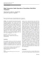
CHAPTER 4: Characteristics Field-Effect Transistor
Val de Loire Program p.57
CHAPTER 4:
CHARACTERISTICS OF FIELD-EFFECT
TRANSISTOR
Table of Contents
4.1. INTRODUCTION 58
4.2. JFET CONSTRUCTION AND SYMBOLS 58
4.3. JFET TERMINAL CHARACTERISTICS 59
4.4. JFET BIAS LINE AND LOAD LINE 62
4.5. MOSFET CONSTRUCTION AND SYMBOLS 63
4.6. MOSFET TERMINAL CHARACTERISTICS 64
Table of Figures
Fig. 4-1 JFET Constructions and Symbols 59
Fig. 4-2 JFET terminal characteristics 61
Fig. 4-3 JFET amplifier bias 62
Fig. 4-4 MOSFET construction and symbol 64
Fig. 4.5 MOSFET terminal characteristics 65
Fig. 4-6 MOSFET amplifier bias 66
CHAPTER 4: Characteristics Field-Effect Transistor
Val de Loire Program p.58
CHAPTER 4:
CHARACTERISTICS OF FIELD-EFFECT
TRANSISTOR
4.1. INTRODUCTION
The operation of the field-effect transistor (FET) can be explained in
terms of only majority-carrier (one-polarity) charge flow; the transistor is
therefore called unipolar.
Two kinds of field-effect devices are widely used: the junction field-
effect transistor (JFET) and the metal-oxide semiconductor field-effect
transistor (MOSFET).
4.2. JFET CONSTRUCTION AND SYMBOLS
Conduction is by the passage of charge carriers from source (S) to
drain (D) through the channel between the gate (G) elements.
The transistor can be an n-channel device (conduction by electrons)
or a p-channel device (conduction by holes); a discussion of n-chanel
devices applies equally to p-channel devices if complementary (opposite
in sign) voltages and currents are used.
CHAPTER 4: Characteristics Field-Effect Transistor
Val de Loire Program p.59
Fig. 4-1 JFET Constructions and Symbols
4.3. JFET TERMINAL CHARACTERISTICS
Output or drain charactersistics for an n-channel JFET in common-
source (CS) connection with
0
GS
v
.
CHAPTER 4: Characteristics Field-Effect Transistor
Val de Loire Program p.60
For a constant value of
GS
v
, JFET acts as a linear resistive device (in
the ohmic region) until the depletion region of the reverse-biased gate-
source junction extends the width of the channel (a condition called
pinchoff).
Above pinchoff but below avalanche breakdown, drain current
D
i
remains nearly constant as
DS
v
is increased. The shorted-gate parameters
DSS
I
and
0
p
V
are defined as indicated in Fig. 4-2(a); typically
0
p
V
is
between 4 and 5 V.
As gate potential decreases, the pinchoff voltage, that is, the source-
to-drain voltage
p
V
at which pinchoff occurs, also decreases,
approximately obeying the equation:
0
p p GS
V V v
CHAPTER 4: Characteristics Field-Effect Transistor
Val de Loire Program p.61
Fig. 4-2 JFET terminal characteristics
The drain current shows an approximate square-law dependence on
source-to-gate voltage for constant values of
DS
v
in the pinchoff region:
2
0
1
GS
D DSS
p
v
i I
V
CHAPTER 4: Characteristics Field-Effect Transistor
Val de Loire Program p.62
4.4. JFET BIAS LINE AND LOAD LINE
Fig. 4-3 JFET amplifier bias
CHAPTER 4: Characteristics Field-Effect Transistor
Val de Loire Program p.63
The commonly used voltage-divider bias arrangement of Fig. 4-3(a)
can be reduced to its equivalent in Fig. 4-3 (b), where the Thévenin
parameters are given by:
1 2
1 2
G
R R
R
R R
and
1
1 2
GG DD
R
V V
R R
.
With
0
G
i
, application of KVL around the gate-source loop of Fig.
4-3(b) yields the equation of the transfer bias line,
GG GS
D
S S
V v
i
R R
Which can be solved simultaneously with transfer characteristics or
plotted as indicated on Fig. 4-2(b) to yield
DQ
I
and
GSQ
V
, two of the
necessary three quiescent variables.
Application of KVL around the drain-source loop of Fig.4-3(b) leads
to the equation of the dc load line,
DD DS
D
S D S D
V v
i
R R R R
So:
DSQ DD S D DQ
V V R R I
4.5. MOSFET CONSTRUCTION AND SYMBOLS
The n-channel MOSFET has only a single p region (called the
substrate), one side of which acts as a conducting channel. A metallic
gate is separated from the conducting channel by an insulating metal
oxide (usually SiO
2
), where the name insulated-gate FET (IGFET) for the
CHAPTER 4: Characteristics Field-Effect Transistor
Val de Loire Program p.64
device. The p-channel MOSFET, formed by interchanging p and n
semiconductor materials, is described by complementary voltages and
currents.
Fig. 4-4 MOSFET construction and symbol
4.6. MOSFET TERMINAL CHARACTERISTICS
In an n-channel MOSFET, the gate (positive plate), metal oxide film
(dielectric), and substrate (negative plate) form a capacitor, the electric
field of which controls channel resistance.
When the positive of the gate reaches a threshold voltage
T
V
(typically 2 to 4 V), sufficient free electrons attracted to the region
immediately beside the metal oxide film (this is called enhancement-
mode operation) to induce a conducting channel of low resistivity. If the
source-to-drain voltage is increased, in the JFET.
CHAPTER 4: Characteristics Field-Effect Transistor
Val de Loire Program p.65
Fig. 4.5 MOSFET terminal characteristics
CHAPTER 4: Characteristics Field-Effect Transistor
Val de Loire Program p.66
Fig. 4-6 MOSFET amplifier bias
The enhancement-mode MOSFET, operating in the pinchoff region,
and if the substrate is shorted to the source. Then:
2
1
GS
D Don
T
v
i I
V
where
GS T
v V
.