Chapter 2 characteristics of bipolar junction transistor
Bạn đang xem bản rút gọn của tài liệu. Xem và tải ngay bản đầy đủ của tài liệu tại đây (302.39 KB, 9 trang )
CHAPTER 2: Characteristics of Bipolar Junction Transistor
Val de Loire Program p.31
CHAPTER 2:
CHARACTERISTICS OF BIPOLAR JUNCTION
TRANSISTOR
Table of Contents
2.1. BJT CONSTRUCTION AND SYMBOLS 32
2.2. COMMON-EMITTER TERMINAL CHARACTERISTICS 33
2.3. CURRENT RELATIONSHIPS 34
2.4. BIAS AND DC LOAD LINES 35
2.5. CAPACITORS AND AC LOAD LINES 38
Table of Figures
Fig. 2-1 Constructions and Symbols of BJT 32
Fig. 2-2 Common-emitter characteristics (npn, Si device) 34
Fig. 2-3 CE amplifier bias circuit 36
Fig. 2-4 DC load line and Q point 38
Fig. 2-5 Capacitors in CE amplifier 38
CHAPTER 2: Characteristics of Bipolar Junction Transistor
Val de Loire Program p.32
CHAPTER 2:
CHARACTERISTICS OF BIPOLAR JUNCTION
TRANSISTOR
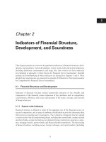
2.1. BJT CONSTRUCTION AND SYMBOLS
The bipolar junction transistor (BJT) is a three-element (emitter,
base, and collector) device, made up of alternating layers of n- and p-type
semiconductor materials. The transistor can be of pnp type (principal
conduction by positive holes) or of npn type (principal conduction by
negative electrons).
Fig. 2-1 Constructions and symbols of BJT
CHAPTER 2: Characteristics of Bipolar Junction Transistor
Val de Loire Program p.33
Table 2-1 Notation for voltages and currents
2.2. COMMON-EMITTER TERMINAL CHARACTERISTICS
The common-emitter (CE) connection is a two-port transistor
arrangement (widely used because of its high current amplification) in
which the emitter shares a common point with the input and output
terminals. The independent port input variables are base current
B
i
and
emitter-to-base voltage
BE
v
, and the independent port output variables are
collector current
C
i
and emitter-to-collector voltage
CE
v
. CE analysis is
based on:
1. Input or transfer characteristics that relate the port input variables
B
i
and
BE
v
, with
CE
v
held constant.
2. Output or collector characteristics that show the functional
relationship between port output variables
C
i
and
CE
v
for constant
B
i
.
CHAPTER 2: Characteristics of Bipolar Junction Transistor
Val de Loire Program p.34
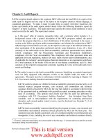
Fig. 2-2 Common-emitter characteristics (npn, Si device)
2.3. CURRENT RELATIONSHIPS
The two pn junctions of the BJT can be independently biased, to
result in four possible transistor operating modes as summarized in Table
2-2.
A junction is forward-biased if the n material is at a lower potential
than the p material, and reverse-biased if the n material is at a higher
potential than the p material.
CHAPTER 2: Characteristics of Bipolar Junction Transistor
Val de Loire Program p.35
Table 2-2 Operating modes
Saturation denotes operation (with
0.2
CE
v V
and
0.5
CB
v V
for
Si devices) such that maximum collector current flows and the transistor
acts much like a closed switch from collector to emitter terminals.
Cutoff denotes operation near the voltage axis of the collector
characteristics, where the transistor acts much like an open switch. Only
leakage current (similar to
o
I
of the diode) flows in this mode of
operation; thus,
0
C CBO
i I
for CE connection.
The inverse mode is a little-used, inefficient active mode with the
emitter and collector interchanged.
The active or linear mode describes transistor operation in the
region to the right of saturation and above cutoff. In this mode, the base
current is increased or amplified
times to become the collector current:
C B
i i
,
E B C
i i i
and
( 1)
E B
i i
.
2.4. BIAS AND DC LOAD LINES
Supply voltages and resistors bias a transistor; that is, they establish
a specific set of dc terminal voltages and currents, thus determining a
CHAPTER 2: Characteristics of Bipolar Junction Transistor
Val de Loire Program p.36
point of active-mode operation (called the quiescent point or Q point).
Usually, quiescent values are unchanged by the application of an ac
signal to the circuit.
Fig. 2-3 CE amplifier bias circuit
Use of the Thevenin equivalent of the circuit to the left of a, b leads
to the circuit of Fig. 2-3(b), where
1 2
1 2
B
R R
R
R R
,
1
1 2
BB CC
R
V V
R R
1
EQ BQ
I I
and assume the emitter-to-base voltage
BEQ
V
is
constant (
0.7
V
and
0.3
V
for Si and Ge, respectively), then KVL
around the emitter loop of Fig. 2-3(b) yields:
1
EQ
BB B BEQ EQ E
I
V R V I R
CHAPTER 2: Characteristics of Bipolar Junction Transistor
Val de Loire Program p.37
1
EQ CQ CQ
I I I
/ 1
BB BEQ
CQ EQ
B E
V V
I I
R R
If component values and the worst-case
value are such that:
1
B B
E
R R
R
Then
EQ
I
(and thus
CQ
I
) is nearly constant, regardless of changes in
; the circuit then has
- independent bias.
Considering
1
:
CC CEQ CEQ
CC
CQ
C E C E C E
CE CC
C
C E C E
dc C E
CE CC
C
dc C E
V V V
V
I
R R R R R R
v V
i
R R R R
R R R
v V
i
R R R
dc C E
R R R
CE CC
C
dc C E
v V
i
R R R
: dc load line with slope
1
dc
R
.
CHAPTER 2: Characteristics of Bipolar Junction Transistor
Val de Loire Program p.38
Fig. 2-4 DC load line and Q point
2.5. CAPACITORS AND AC LOAD LINES
Fig. 2-5 Capacitors in CE amplifier
CHAPTER 2: Characteristics of Bipolar Junction Transistor
Val de Loire Program p.39
1. Coupling capacitors
C
C
confine dc quantities to the transistor
and its bias circuitry.
2. Bypass capacitors
E
C
effectively remove the gain-reducing
emitter resistor
E
R
insofar as ac signals are concerned, while allowing
E
R
to play its role in establishing
- independent bias.
1
0
C
Z
C
when C is large enough.
With ac signal:
ce c ac
v i R
//
C L
ac C L
C L
R R
R R R
R R
CEQ
CE
C CQ
ac ac
V
v
i I
R R
: ac load line with slope
1
ac
R
and intersects
the dc load line at the Q point.