RƠ LE KHOẢNG CÁCH Grz200(6F2S1905) 0 41
Bạn đang xem bản rút gọn của tài liệu. Xem và tải ngay bản đầy đủ của tài liệu tại đây (11.42 MB, 998 trang )
6F2S1905 (0.41)
INSTRUCTION MANUAL
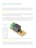
Distance Protection IED
GRZ 200
(Revision 0.41)
6F2S1905 (0.41)
Safety Precautions
Before using this equipment, please read this chapter carefully.
This chapter describes the safety precautions recommended when using the GR
equipment. Before installing and using the equipment, this chapter must be thoroughly
read and understood.
Explanation of symbols used
Signal words such as DANGER, WARNING, and CAUTION, will be followed by
important safety information that must be carefully reviewed.
DANGER
WARNING
CAUTION
Indicates an imminently hazardous situation which will result
indeath or serious injury if you do not follow the instructions.
Indicates a potentially hazardous situation which could result in
death or serious injury if you do not follow the instructions.
Indicates a potentially hazardous situation which if not avoided,
may result in minor injury or moderate injury or property
damage.
DANGER
•Current transformer circuit
Never allow the current transformer (CT) secondary circuit connected to this equipment to
be opened while the primary system is live. Opening the CT circuit will produce a
dangerously high voltage.
WARNING
•Exposed terminals
Do not touch the terminals of this equipment while the power is on, as the high voltage
generated is dangerous.
•Residual voltage
Hazardous voltage can be present in the DC circuit just after switching off the DC power
supply. It takes approximately 30 seconds for the voltage to discharge.
•Fiber optic
Invisible laser radiation
Do not view directly with optical instruments.
i
6F2S1905 (0.41)
CAUTION
•Earth
The earthing terminal of the equipment must be securely earthed.
CAUTION
•Operating environment
The equipment must only be used within the range of ambient temperature, humidity and
dust detailed in the specification and in an environment free of abnormal vibration.
•Ratings
Before applying AC voltage and current or the DC power supply to the equipment, check
that they conform to the equipment ratings.
•Printed circuit board
Do not attach and remove printed circuit boards when the DC power to the equipment is
on, as this may cause the equipment to malfunction.
•External circuit
When connecting the output contacts of the equipment to an external circuit, carefully
check the supply voltage used in order to prevent the connected circuit from overheating.
•Connection cable
Carefully handle the connection cable without applying excessive force.
•Modification
Do not modify this equipment, as this may cause the equipment to malfunction.
•Short-wire
Do not remove a short-wire which is mounted at the terminal on the rear of the equipment
before shipment, as this may cause the performance of this equipment such as withstand
voltage, etc., to reduce.
ii
6F2S1905 (0.41)
•Disposal
This equipment contains neither expendable supplies nor parts that can be recycled.
When disposing of this equipment, the customer must contact an operator responsible for
industrial waste disposal, and request that the operator dispose of this equipment in
accordance with the local waste disposal regulations; otherwise the person who disposes
of this equipment may be punished under local regulations. When disposing of this
equipment is practiced by the customer acting on their own behalf, it must be done so in a
safe manner according to local regulations. For further information in terms of the disposal,
the customer shall contact to a local dealer and sales staff at Toshiba.
This equipment contains neither expendable supplies nor recyclables.
•Plastics material
This equipment contains the following plastics material.
- ABS, Polycarbonate, Acrylic resins, Nylon 66, and others.
Equipment installation and operation
•Equipment installation
Never remove cables at frame ground terminals (FGs) while the AC/DC power supplies.
•Equipment operation
The user shall have responsibilities to use and install the equipment where the
specifications are designated by the manufacture. Never operate the equipment on the
condition where the manufacture cannot intend. Otherwise, the safety function furnished
into the equipment may not be operated properly.
•Symbols
Symbol
Description
Protective conductor terminal
Caution, risk of electric shock
iii
6F2S1905 (0.41)
Liability, copyright and others
•Disclaimer of liability
We have checked the description of this manual against the hardware and software
described, but we cannot guarantee that all deviations have been eliminated from the
description completely; hence, no liability can be accepted for any errors or omissions
contained in the information given. We review the information in this manual regularly
and there will be some corrections in subsequent editions. We reserve the right to
make technical improvements without notice.
ãCopyright
Copyright â Toshiba 2014, 2015. All rights reserved.
ãRegistered Trademarks
Product/Equipment names (mentioned herein) may be trademarks of their respective
companies.
iv
6F2S1905 (0.41)
Contents
1
2
Introduction ............................................................................................................................................ 1
1.1
Protection functions ........................................................................................................................ 2
1.2
Control.............................................................................................................................................. 3
1.3
Monitoring and metering functions ............................................................................................... 3
1.4
Hardware overview ......................................................................................................................... 4
1.5
Symbols used in logical diagrams .................................................................................................. 5
1.6
Abbreviation .................................................................................................................................... 9
1.7
Function Block (FB), Function ID, Signal number ..................................................................... 10
Relay application .................................................................................................................................. 11
2.1
Distance protection (ZS/ZG with 6 zones) ................................................................................... 12
2.1.1
Principle of distance measurement ...................................................................................... 12
2.1.2
Element characteristic in distance relay.............................................................................. 16
2.1.3
Common application for ZS and ZG...................................................................................... 31
2.1.4
Extended application ............................................................................................................. 37
2.1.5
Command protection feature................................................................................................. 37
2.1.6
Scheme logic ........................................................................................................................... 42
2.1.7
Setting list .............................................................................................................................. 45
2.1.8
Data ID ................................................................................................................................... 60
2.2
Distance carrier command protection (DISCAR) ........................................................................ 75
2.2.1
Permissive underreach protection (PUP) ............................................................................. 75
2.2.2
Permissive overreach protection (POP) ................................................................................ 77
2.2.3
Unblocking overreach protection (UOP) .............................................................................. 80
2.2.4
Blocking overreach protection (BOP) ................................................................................... 82
2.2.5
Protection for week infeed terminal ..................................................................................... 85
2.2.6
Countermeasure for current reversal ................................................................................... 87
2.2.7
Setting ..................................................................................................................................... 90
2.2.8
Data ID ................................................................................................................................... 91
2.3
Directional earth fault command protection (DEFCAR) ............................................................ 93
2.3.1
Permissive overreach protection (POP) ................................................................................ 93
2.3.2
Unblocking overreach protection (UOP) .............................................................................. 97
2.3.3
Blocking overreach protection (BOP) ................................................................................... 97
2.3.4
Coordination with DISCAR protection ................................................................................. 99
2.3.5
Setting ................................................................................................................................... 101
2.3.6
Data ID ................................................................................................................................. 102
2.4
Direct transfer trip (DTT) ........................................................................................................... 104
2.4.1
Setting ................................................................................................................................... 104
2.4.2
Scheme logic ......................................................................................................................... 105
2.4.3
Setting ................................................................................................................................... 106
v
6F2S1905 (0.41)
2.4.4
2.5
Data ID ................................................................................................................................. 107
Overcurrent protection (OC)....................................................................................................... 108
2.5.1
Relay polarity ....................................................................................................................... 108
2.5.2
Inverse definite mean time and definite time characteristic ........................................... 112
2.5.3
Threshold value for operation ............................................................................................. 118
2.5.4
Reset Ratio............................................................................................................................ 118
2.5.5
Miscellaneous functions....................................................................................................... 118
2.5.6
Scheme logic ......................................................................................................................... 120
2.5.7
Setting ................................................................................................................................... 122
2.5.8
Data ID ................................................................................................................................. 125
2.6
Earth fault protection (EF) ......................................................................................................... 127
2.6.1
Relay polarity ....................................................................................................................... 127
2.6.2
Inverse time and definite time delay characteristic .......................................................... 130
2.6.3
Threshold level for operation .............................................................................................. 136
2.6.4
Reset Ratio............................................................................................................................ 136
2.6.5
Miscellaneous functions....................................................................................................... 136
2.6.6
Scheme logic ......................................................................................................................... 138
2.6.7
Setting ................................................................................................................................... 139
2.6.8
Data ID ................................................................................................................................. 142
2.7
Negative sequence overcurrent protection (OCN) .................................................................... 143
2.7.1
Relay polarity ....................................................................................................................... 143
2.7.2
Inverse time and definite time delay characteristic .......................................................... 146
2.7.3
Threshold value .................................................................................................................... 152
2.7.4
Reset Ratio............................................................................................................................ 152
2.7.5
Miscellaneous functions....................................................................................................... 152
2.7.6
Scheme logic ......................................................................................................................... 153
2.7.7
Setting ................................................................................................................................... 155
2.7.8
Data ID ................................................................................................................................. 159
2.8
Thermal overload function (THM) ............................................................................................. 160
2.8.1
Thermal state determination .............................................................................................. 160
2.8.2
Thermal characteristic ........................................................................................................ 161
2.8.3
Scheme logic ......................................................................................................................... 163
2.8.4
Setting ................................................................................................................................... 164
2.8.5
Data ID ................................................................................................................................. 165
2.9
Broken conductor protection (BCD) ........................................................................................... 166
2.9.1
Equivalent circuit for a one-phase series fault .................................................................. 166
2.9.2
Characteristic and setting ................................................................................................... 167
2.9.3
Miscellaneous functions....................................................................................................... 168
2.9.4
Scheme logic ......................................................................................................................... 168
vi
6F2S1905 (0.41)
2.9.5
Setting ................................................................................................................................... 169
2.9.6
Data ID ................................................................................................................................. 170
2.10
Circuit breaker fail protection (CBF)......................................................................................... 171
2.10.1
CBF operation and its elements ......................................................................................... 172
2.10.2
Re-trip feature ...................................................................................................................... 172
2.10.3
Backup feature ..................................................................................................................... 173
2.10.4
Scheme logic ......................................................................................................................... 174
2.10.5
Operation timing .................................................................................................................. 175
2.10.6
Setting ................................................................................................................................... 176
2.10.7
Data ID ................................................................................................................................. 177
2.11
Switch on to fault (SOTF-OC) .................................................................................................... 179
2.11.1
Scheme logic and setting ..................................................................................................... 179
2.11.2
Setting ................................................................................................................................... 181
2.11.3
Data ID ................................................................................................................................. 181
2.12
Overvoltage protection for phase-to-neutral (OV) .................................................................... 182
2.12.1
Drop-off and pickup characteristic ..................................................................................... 182
2.12.2
Delay for the operation of the OV element ........................................................................ 182
2.12.3
Time characteristic .............................................................................................................. 182
2.12.4
Miscellaneous functions....................................................................................................... 185
2.12.5
Scheme logic ......................................................................................................................... 186
2.12.6
Setting list ............................................................................................................................ 187
2.12.7
Data ID ................................................................................................................................. 188
2.13
Overvoltage protection for phase-to-phase (OVS)..................................................................... 189
2.13.1
Drop-off and pickup setting ................................................................................................. 189
2.13.2
Delay for the operation of the OVS element ...................................................................... 189
2.13.3
Time characteristic .............................................................................................................. 189
2.13.4
Miscellaneous functions....................................................................................................... 192
2.13.5
Scheme logic ......................................................................................................................... 193
2.13.6
Setting list ............................................................................................................................ 194
2.13.7
Data ID ................................................................................................................................. 196
2.14
Phase under-voltage protection (UV) ......................................................................................... 197
2.14.1
Delay for the operation of the UV element ........................................................................ 197
2.14.2
Drop-off and pick-up characteristic .................................................................................... 197
2.14.3
Time characteristic .............................................................................................................. 197
2.14.4
Miscellaneous functions....................................................................................................... 200
2.14.5
Scheme logic ......................................................................................................................... 201
2.14.6
Setting ................................................................................................................................... 203
2.14.7
Data ID ................................................................................................................................. 204
2.15
Phase-to-phase under-voltage protection (UVS) ....................................................................... 205
vii
6F2S1905 (0.41)
2.15.1
Delay for the operation of the UVS element ...................................................................... 205
2.15.2
Drop-off and pick-up characteristic .................................................................................... 205
2.15.3
Time characteristic .............................................................................................................. 205
2.15.4
Miscellaneous functions....................................................................................................... 208
2.15.5
Scheme logic ......................................................................................................................... 209
2.15.6
Setting ................................................................................................................................... 211
2.15.7
Data ID ................................................................................................................................. 212
2.16
Out of step tripping protection by distance relay (OSTZ) ........................................................ 213
2.16.1
Phenomenon and principle of out-of-step ........................................................................... 213
2.16.2
Function features ................................................................................................................. 214
2.16.3
Operation zones and element characteristics .................................................................... 215
2.16.4
Scheme logic and setting ..................................................................................................... 216
2.16.5
Setting ................................................................................................................................... 218
2.16.6
Data ID ................................................................................................................................. 219
2.17
Inrush current detection function (ICD).................................................................................... 220
2.17.1
Characteristic ....................................................................................................................... 220
2.17.2
Setting ................................................................................................................................... 220
2.17.3
Scheme logic ......................................................................................................................... 220
2.17.4
Setting ................................................................................................................................... 221
2.17.5
Data ID ................................................................................................................................. 221
2.18
Fail safe (FS)................................................................................................................................ 222
2.18.1
Overcurrent element (OCFS) .............................................................................................. 222
2.18.2
Phase current change detector element (OCDFS) ............................................................. 222
2.18.3
Earth fault current element (EFFS) ................................................................................... 223
2.18.4
Multi-level overcurrent elements (OCMFS) ...................................................................... 223
2.18.5
Under-voltage element for phase-to-earth (UVFS) ........................................................... 224
2.18.6
Under-voltage element for phase-to-phase (UVSFS) ........................................................ 224
2.18.7
Under-voltage change detection element (UVDFS) .......................................................... 224
2.18.8
Scheme logic ......................................................................................................................... 225
2.18.9
Setting ................................................................................................................................... 227
2.18.10
2.19
Data ID list ....................................................................................................................... 228
VT failure detection (VTF).......................................................................................................... 229
2.19.1
VTF features......................................................................................................................... 229
2.19.2
Operation for the VTF function .......................................................................................... 230
2.19.3
VTF Logic ............................................................................................................................. 230
2.19.4
Setting ................................................................................................................................... 233
2.19.5
Data ID ................................................................................................................................. 234
2.20
CT failure detection (CTF).......................................................................................................... 235
2.20.1
CTF features......................................................................................................................... 235
viii
6F2S1905 (0.41)
2.20.2
Operation for the CTF function .......................................................................................... 235
2.20.3
CTF logic ............................................................................................................................... 236
2.20.4
Setting ................................................................................................................................... 238
2.20.5
Data ID ................................................................................................................................. 239
2.21
Single-end fault locator (FL-A)................................................................................................... 240
2.21.1
Computation method ........................................................................................................... 240
2.21.2
Output of FL computation on display................................................................................. 243
2.21.3
Setting and operation .......................................................................................................... 245
2.21.4
Scheme logic ......................................................................................................................... 250
2.21.5
Setting ................................................................................................................................... 252
2.21.6
Data ID ................................................................................................................................. 254
2.22
Autoreclose (ARC) ....................................................................................................................... 255
2.22.1
Selection of breaker system................................................................................................. 256
2.22.2
Number of shots ................................................................................................................... 257
2.22.3
Single-phase auto-reclose mode (SPAR) ............................................................................. 258
2.22.4
Three-phase auto-reclose mode (TPAR) ............................................................................. 260
2.22.5
Single-phase and three-phase auto-reclose (SPAR&TPAR).............................................. 263
2.22.6
Multi-phase auto-reclose mode (MPAR) ............................................................................. 263
2.22.7
Final trip ............................................................................................................................... 264
2.22.8
User configurable auto-reclose (ORIGINAL) ..................................................................... 264
2.22.9
Disable auto-reclose (Off) .................................................................................................... 264
2.22.10
Success decision of reclose operation .............................................................................. 265
2.22.11
Dead time counter for evolving fault .............................................................................. 265
2.22.12
Reclaim time (TREADY) .................................................................................................. 267
2.22.13
Test shot function ............................................................................................................. 267
2.22.14
Setting ............................................................................................................................... 268
2.22.15
Data ID.............................................................................................................................. 270
2.23
Voltage check for autoreclose (VCHK) ....................................................................................... 276
2.23.1
VCHK1 for 1CB system ....................................................................................................... 276
2.23.2
VCHK1 and VCHK2 for 1.5CB system .............................................................................. 278
2.23.3
Scheme for synchronism ...................................................................................................... 279
2.23.4
VCHK1 setting for 1CB ....................................................................................................... 282
2.23.5
VCHK1 and VCHK2 settings for 1.5CB ............................................................................. 286
2.23.6
Scheme and activation ......................................................................................................... 288
2.23.7
Setting ................................................................................................................................... 290
2.23.8
Data ID ................................................................................................................................. 292
2.24
Trip circuit (TRC) ........................................................................................................................ 293
2.24.1
Operation mode .................................................................................................................... 293
2.24.2
Scheme logic ......................................................................................................................... 294
ix
6F2S1905 (0.41)
2.24.3
Setting ................................................................................................................................... 299
2.24.4
Data ID ................................................................................................................................. 300
2.25
3
Protection common (PROT_COMMON) .................................................................................... 302
2.25.1
Decision of CB open/close status ......................................................................................... 302
2.25.2
Decision of DS open/close status ......................................................................................... 306
2.25.3
Dead line detection .............................................................................................................. 307
2.25.4
Detection of current change (OCD)..................................................................................... 309
2.25.5
Setting ................................................................................................................................... 310
2.25.6
Data ID ................................................................................................................................. 311
Control and monitoring application for common ............................................................................. 313
3.1
Control scheme ............................................................................................................................ 314
3.2
Control mode................................................................................................................................ 317
3.2.1
Select-before-operation mode (SBO) ................................................................................... 317
3.2.2
Direct-operation mode (DIR) ............................................................................................... 318
3.3
Common controls (CMNCTRL) .................................................................................................. 320
3.3.1
Double command blocking (DCB) ....................................................................................... 320
3.3.2
PLC_BIT/UNIT/BOOL signal ............................................................................................. 323
3.3.3
Provision of selected status ................................................................................................. 324
3.3.4
Miscellaneous settings ......................................................................................................... 325
3.3.5
Setting ................................................................................................................................... 326
3.3.6
Signal .................................................................................................................................... 327
3.4
Local, remote and PLC control ................................................................................................... 332
3.4.1
Local control ......................................................................................................................... 332
3.4.2
Remote control...................................................................................................................... 332
3.4.3
Programmable logic control (PLC)...................................................................................... 333
3.4.4
Signal for Local/Remote control .......................................................................................... 333
3.5
LED reset function (LEDR) ........................................................................................................ 335
3.5.1
Select logic for resetting LEDs ............................................................................................ 336
3.5.2
Cancel logic in SBO mode.................................................................................................... 339
3.5.3
Operate logic for SBO/DIR mode ........................................................................................ 340
3.5.4
Settings in LED logics ......................................................................................................... 342
3.5.5
Mapping for IEC61850 commination ................................................................................. 343
3.5.6
Setting ................................................................................................................................... 347
3.5.7
Signal .................................................................................................................................... 348
3.6
Counter function for the general (GCNT) ................................................................................. 349
3.6.1
Counter setting for a signal................................................................................................. 350
3.6.2
Select logics for SBO/DIR modes ........................................................................................ 352
3.6.3
Cancel logics for SBO mode................................................................................................. 359
3.6.4
Operate logics for SBO/DIR modes ..................................................................................... 361
x
6F2S1905 (0.41)
3.6.5
Mapping for IEC61850 communication.............................................................................. 365
3.6.6
Setting ................................................................................................................................... 369
3.6.7
Data ID ................................................................................................................................. 370
3.7
4
Mode control function (MDCTRL).............................................................................................. 379
3.7.1
State monitor of TEST-FB ................................................................................................... 379
3.7.2
Interface for IEC 61850 ....................................................................................................... 379
3.7.3
Setting ................................................................................................................................... 380
3.7.4
Signal .................................................................................................................................... 381
Control and monitoring application for simple ................................................................................ 383
4.1
Single position device function (SPOS)...................................................................................... 384
4.1.1
Selection logic for SBO/DIR modes ..................................................................................... 385
4.1.2
Cancel logics for SBO mode................................................................................................. 401
4.1.3
Operate logics for SBO/DIR modes ..................................................................................... 405
4.1.4
Setup for BIO module .......................................................................................................... 419
4.1.5
Mapping SPOS function signals for IEC61850 commination ........................................... 428
4.1.6
Setting ................................................................................................................................... 433
4.1.7
Signal .................................................................................................................................... 434
4.2
Double position controller with synchronizing-checking (DPSY) ............................................ 436
4.2.1
Selection logic for SBO/DIR modes ..................................................................................... 437
4.2.2
Cancel logics for SBO mode................................................................................................. 452
4.2.3
Operate logics for SBO/DIR modes ..................................................................................... 456
4.2.4
Operation counter ................................................................................................................ 472
4.2.5
Operation time measurement ............................................................................................. 476
4.2.6
Setup for BIO module .......................................................................................................... 478
4.2.7
Mapping DPSY function signals for IEC61850 communication....................................... 489
4.2.8
Setting ................................................................................................................................... 493
4.2.9
Signal .................................................................................................................................... 495
4.3
Software switch controller function (SOFTSW) ........................................................................ 499
4.3.1
SOTFSW output-states........................................................................................................ 500
4.3.2
Control logics for SBO/DIR modes ...................................................................................... 502
4.3.3
Cancel logics for SBO mode................................................................................................. 510
4.3.4
Operate logics for SBO/DIR modes ..................................................................................... 511
4.3.5
Mapping SOFTSW1 function signal for IEC61850 commination .................................... 518
4.3.6
Setting ................................................................................................................................... 523
4.3.7
Signal .................................................................................................................................... 524
4.4
Operation time reset function (OPTIMRSTCTRL) ................................................................... 535
4.4.1
Select logic for SBO/DIR modes .......................................................................................... 537
4.4.2
Cancel logic in SBO mode.................................................................................................... 540
4.4.3
Operate logic for SBO/DIR modes....................................................................................... 541
xi
6F2S1905 (0.41)
4.4.4
Mapping for IEC61850 commination ................................................................................. 543
4.4.5
Setting ................................................................................................................................... 548
4.4.6
Signal .................................................................................................................................... 549
4.5
4.5.1
Feature of TOTALTIM ......................................................................................................... 551
4.5.2
Preparation for TOTALTIM operation ............................................................................... 553
4.5.3
Setting ................................................................................................................................... 554
4.5.4
Signal .................................................................................................................................... 555
4.6
5
Total time measurement function (TOTALTIM) ....................................................................... 550
Synchronizing check for different network (SYNDIF) ............................................................. 558
4.6.1
Relays to line-outage check ................................................................................................. 559
4.6.2
Relays to synchronization check ......................................................................................... 561
4.6.3
Line-outage check ................................................................................................................ 566
4.6.4
Synchronization check ......................................................................................................... 571
4.6.5
Relay selection for checking synchronization .................................................................... 575
4.6.6
Voltage selection for line arrangement ............................................................................... 577
4.6.7
Setting ................................................................................................................................... 579
4.6.8
Signal .................................................................................................................................... 581
Technical Description ......................................................................................................................... 585
5.1
IED case and module slots.......................................................................................................... 588
5.1.1
3/4 case for Compression-type terminal ............................................................................. 588
5.1.2
1/2 case for Compression-type terminal ............................................................................. 590
5.2
Transformer module for AC analog input (VCT)....................................................................... 592
5.2.1
VCT in Type 11B .................................................................................................................. 593
5.2.2
VCT in Type 12B .................................................................................................................. 594
5.2.3
Constitution of VCT ............................................................................................................. 595
5.2.4
Setting VCT ratio ................................................................................................................. 597
5.2.5
Selection of rated current .................................................................................................... 598
5.3
Signal processing and communication module (CPU) .............................................................. 600
5.3.1
Processing module................................................................................................................ 600
5.3.2
Communication modules ..................................................................................................... 602
5.3.3
Location of communication modules................................................................................... 604
5.4
Binary IO module (BI, BO, and BIO)......................................................................................... 605
5.4.1
Binary input feature for Compression-type terminal ....................................................... 606
5.4.2
Binary input circuit ............................................................................................................. 607
5.4.3
Binary output feature for Compression-type terminal ..................................................... 615
5.4.4
Binary output circuit ........................................................................................................... 617
5.4.5
Structure of binary IO Module for Compression-type terminal ....................................... 623
5.4.6
Settings of binary input circuits ......................................................................................... 628
5.4.7
Data IDs of binary input circuits ........................................................................................ 630
xii
6F2S1905 (0.41)
5.4.8
Settings of binary output circuits ....................................................................................... 632
5.4.9
Data IDs of binary output circuits ...................................................................................... 634
5.5
Power supply module (PWS) ...................................................................................................... 636
5.6
Human Machine Interface (HMI) .............................................................................................. 638
5.6.1
HMI Outlook......................................................................................................................... 638
5.6.2
LED indicators (#3–#26)...................................................................................................... 639
Engineering tool.................................................................................................................................. 642
6
6.1
Overview of GR-TIEMS .............................................................................................................. 643
PLC function ....................................................................................................................................... 644
7
7.1
Overview of PLC function ........................................................................................................... 645
7.2
Check of PLC error ...................................................................................................................... 645
7.3
PLC driver.................................................................................................................................... 646
Recording Function ............................................................................................................................ 648
8
8.1
Fault Recording ........................................................................................................................... 649
8.2
Event Recording .......................................................................................................................... 650
8.3
Disturbance Recording................................................................................................................ 651
Metering Function .............................................................................................................................. 653
9
9.1
Display of current metering........................................................................................................ 654
9.2
Demand value for metering ........................................................................................................ 655
Automatic supervision .................................................................................................................... 656
10
10.1
Basic concept of supervision ....................................................................................................... 657
10.2
Relay Monitoring ......................................................................................................................... 657
10.3
Voltage transformer failure supervision .................................................................................... 659
10.4
Circuit breaker contact monitoring............................................................................................ 659
10.5
Disconnector contact monitoring................................................................................................ 659
10.6
PLC Data and IEC61850 Mapping Data Monitoring ............................................................... 659
10.7
IEC61850 Communication Monitoring ...................................................................................... 659
10.8
Failure alarms ............................................................................................................................. 659
10.9
Trip blocking ................................................................................................................................ 660
Communication protocol ................................................................................................................. 661
11
11.1
LAN communication ................................................................................................................... 662
11.1.2
Settings list........................................................................................................................... 670
11.1.3
Data ID ................................................................................................................................. 672
11.2
IEC 61850 communication.......................................................................................................... 673
11.2.1
Settings for IEC 61850 communications ............................................................................ 674
11.2.2
How to monitor IEC 61850 communications ..................................................................... 676
11.2.3
Setting ................................................................................................................................... 676
12
12.1
User interface .................................................................................................................................. 677
Outline ......................................................................................................................................... 678
xiii
6F2S1905 (0.41)
12.2
HMI operation ............................................................................................................................. 682
12.3
Record sub-menu ......................................................................................................................... 686
12.4
Monitoring sub-menu .................................................................................................................. 693
12.5
Setting sub-menu ........................................................................................................................ 702
12.6
I/O setting sub-menu................................................................................................................... 717
12.7
Time sub-menu ............................................................................................................................ 724
12.8
Test sub-menu.............................................................................................................................. 732
12.9
Information sub-menu ................................................................................................................ 739
12.10
Security setting sub-menu ...................................................................................................... 741
12.11
Control sub-menu .................................................................................................................... 743
13
Installation ...................................................................................................................................... 748
14
Commissioning and Maintenance.................................................................................................. 752
14.1
Cautions ....................................................................................................................................... 754
14.2
Preparations ................................................................................................................................ 755
Appendix 1
Signal list for common function ...................................................................................... 768
Appendix 2
Case outline ...................................................................................................................... 870
Appendix 3
Typical external connection ............................................................................................. 879
Appendix 4
IEC61850 MICS and PICS .............................................................................................. 884
Appendix 5
Ordering ............................................................................................................................ 933
Appendix 6
Technical data ................................................................................................................... 943
Appendix 7
Manufacture setting ......................................................................................................... 957
Appendix 8
Methods of replacing modules ......................................................................................... 962
Appendix 9
Rack mounting.................................................................................................................. 966
Appendix 10
CT requirement ................................................................................................................ 973
Appendix 11
Input dummy for relay application ................................................................................. 976
xiv
6F2S1905 (0.41)
1
Introduction
- 1 -
6F2S1905 (0.41)
GRZ200 distance protection is designed to provide distance protection with control
applications. The GRZ200—intelligent electronic device (IED)—provides you with the
flexibility to meet their application and engineering requirements in addition to offering
excellent performance, the high quality and reliability.
1.1 Protection functions
The IED has a number of protection functions and these functions are being optimized for
transmission or distribution systems. The followings functions, which the IED incorporates
and for which you key their settings with human machine interface (HMI), operate well with
mutual linkage between functions.
[OC]
Directional/non-directional phase over current protection
This function includes four-stages of threshold for faults. This function includes inverse time
and definite time characteristics. Depending upon IED model is the characteristics are
relevant to current and voltage measurement quantities with directional or non-directional
characteristic provided for each stage.
[EF]
Directional/Non-directional phase earth fault protection
This function includes four-stages of threshold for fault protection. The choice of characteristic
is selectable between inverse time, and definite time. Note that the selection of a directional
characteristic is available when the IED model is relevant to both current and voltage
measurement quantities as with the OC function.
[SOTF-OC] Switch on to fault protection
In order to quickly remove a fault which may occur when a faulted line or bus-bar is energized,
the SOTF protection will be operational for a certain period after the circuit breaker closes.
[FS]
Fail-safe protection
The IED is provided with Fail-safe elements which function as a check relay and enhance
security against a fault a power system with week infeed, or prevent a false tripping due to a
signal failure in the protection system.
[VTF] VT failure detection function
When a fault occurs in the secondary circuit of a voltage transformer (VT), voltage dependent
measuring elements may operate incorrectly. The voltage transformer failure detection
function (VTF) avoids such as the incorrect operation. When the VTF detects a VT failure, it
blocks voltage dependent protections instantaneously.
[CTF] CT failure detection function
When there is a fault in the secondary circuit of a current transformer (CT), current
dependent measuring elements may operate incorrectly. The detection function for current
transformer failure (CTF) avoids the above incorrect operation. When the CTF detects a CT
failure, it blocks current dependent protections instantaneously.
- 2 -
6F2S1905 (0.41)
[FL] Single-end fault locator
When a fault is detected, fault locator can determine distance between the IED and the fault
point.
[ARC] Auto-re-close function
After the IED trips a circuit breaker (CB) due to a fault on the Line, the automatic re-close
function can close the CB so as to reenergize the power.
[VCHK] Voltage check for auto-re-close function
This function is used in corporation with the function of auto-re-close (ARC). The VCHK
checks voltage and frequency differences between a Bus-bar and Lines, and permits the ARC
the operation.
1.2 Control
The IED provides control functions for circuit breakers and isolators, other switchgear and
transformers. These functions, are operated via the HMI, or other functions, are also
available such as automatic sequence control, interlocking operation and manual override
operation.
[LRST] Trip LED reset function
When the LED is continuously illuminated following the completion of a trip operation, it can
be turned off using LRST.
[L/R]
Remote/Local control function
When control of the object device is required, this function allows the selection of the control
command for either local or remote, (dispatch site/control centre) operation.
[GCNT] General pulse counter function
This function can observe a signal, for example the output of a PLC function and counts the
number of pulses for the signal. The total number of pulses counted is recorded.
[MDCTRL] Mode control function
This function enables an interface for test function block (TSET-FB). With this interface, a
mode change command is made within the IED for the TEST-FB.
1.3 Monitoring and metering functions
The monitoring and metering functions, using the HMI, display status, settings, data and
others. The user can also see information on a PC with “GR-series Toshiba IED Engineering
and Monitoring Software (GR-TIEMS)” at local and remote end both.
- 3 -
6F2S1905 (0.41)
Monitoring function:
This function supervises status of protection functions, and displays power system quantities.
It also shows failure information in the CT and VT.
Fault record function:
Such function records the state of a fault when the trip command is issued. It also memorizes
the fault data. The user can see, with the IED screen, these data with additional information:
date & time, fault phase, tripping phase, tripping mode, fault location, operating mode and
power system quantities.
Event record function:
Such function provides recording feature that memories any event occurred in the IED.
Disturbance record function:
Disturbance record is triggered by fault detection. The user can see the waveform recorded by
this function using GR-TIEMS.
1.4 Hardware overview
A human machine interface (HMI) consisting of a screen, indication lights, operation and
function keys, monitoring jacks and a USB connector are provided in the IED. The IED has
signal terminals at the rear. Input and output module circuits are provided for these signals.
HMI features:
- Menu-driven human interfaces for relay setting or viewing of stored data.
- A standard LCD or a large LCD screen, LED display, 7 function keys and operation keys
- Password protection
Communication features:
- USB for GR-TIEMS
- RS485 for Substation control and Automation System (SAS) with IEC60870-5-103 protocol
- Fiber Optic (FO, option) for SAS with IEC60870-5-103 protocol
- 100BASE-TX, or -FX for SAS with IEC61850 protocol
Module circuits and others:
- Binary inputs and binary outputs with configurable features
- AC inputs
- Programmable logic for I/O configuration, alarms, indications, recording and others
- Automatic supervision
- 4 -
6F2S1905 (0.41)
1.5
Symbols used in logical diagrams
Symbols used in the scheme logic and their meanings are as follows:
(i)
Relay element, signal-monitoring point, PLC connection point, and
Mapping point
1. Marked with
: Relay elements
2. Marked with
: Signal-monitoring point designated by Element ID number
1Note
that the symbol can be connected with what follows:
A binary output (BO) circuit
A LED circuit
2Like
in the BO and LED circuits, it can also be connected or mapped to what follows:
A PLC input point
The IEC 61850 logical node (LN) to send a signal for the SAS
3. Marked with
: PLC connection points designated by Element ID and its name
Element ID (or Data ID)
1Note
Signal name corresponding to Element or Data ID
that the symbol can be used for the reception point coming from the output of PLC
logics.
2Note
that the user cannot use the PLC connection point straightforward when the relay and
control and monitoring function is operated in sub-CPU. Therefore, an alternative
connection method (PLC driver/Input dummy) is provided in place of the PLC connection
point; the requirement of the alternative connection method depends on the model.
3The
PLC driver is discussed in Chapter PLC function; the input dummy is discussed in
Appendix Input dummy for relay application.
4. Marked with
Data ID
1Note
: Mapping points designated by Data ID and its name
Signal name corresponding to Data ID
that the symbol can be used as a signal reception-point coming from the SAS. The
reception point is mapped to the LN of the IEC61850.
- 5 -
6F2S1905 (0.41)
(ii)
Timer symbol
Delay timer
Delayed pick-up timer
t
0
Fixed timer (XXX: Set time)
XXX
t
0
Variable timer (XXX ─ YYY: Setting range)
XXX ─ YYY
Delayed drop-off timer
0
t
Fixed timer (XXX: Set time)
XXX
0
t
Variable timer (XXX ─ YYY: Setting range)
XXX ─YYY
One-shot timer
Output
A
XXX - YYY
XXX - YYY:
A
Output
Setting range
- 6 -
6F2S1905 (0.41)
(iii)
Logic symbol
AND gate
A
&
B
Output
A
B
Output
1
1
1
1
0
0
0
1
0
0
0
0
A
B
Output
1
1
1
1
0
1
0
1
1
0
0
0
A
B
Output
1
1
0
1
0
1
0
1
1
0
0
0
OR gate
A
B
≥1
Output
XOR gate
A
B
A
=1
Output
Signal inversion
1
Output
- 7 -
A
Output
0
1
1
0
6F2S1905 (0.41)
(iv)
Flip-flop symbol
A
S
B
R
(v)
Output
A
B
Output
0
0
No change
1
0
1
0
1
0
1
1
0
A
Switch
Output
1
On
1
1
Off
0
Scheme switch
A
+
On
On
Output
Output
Switch
Output
On
1
Off
0
- 8 -
6F2S1905 (0.41)
1.6
Abbreviation
Abbreviation
Description
ADC
Analog to digital converter
BCU
Bay Control Unit
BCPU
Bay Control and Protection Unit
BI
Binary Input module or circuit
BO
Binary Output module or circuit
BIO
Binary Input and Output module or circuit
CB
Circuit Breaker
CPU
Signal processing and communication module
CT
Current Transformer
DS
Disconnecting Switch
EF
Earth Fault
ES
Earthing Switch
EWS
Engineering Workstation in the substation
GPS
Global Positioning System
GR-TIEMS
GR-series Toshiba IED Engineering and Monitoring Software
GUI
Graphical User Interface
HMI
Human Machine Interface
IED
Intelligent Electronic Device
IDMT
Inverse Definite Minimum Time
LCD
Liquid Crystal Display for IED screen (standard LCD screen)
LCP
Local Panel for Controlling
LED
Light Emitting Diode
MIMIC
NA
MIMIC display panel for IED screen (Large LCD screen)
Not Applicable
NGR
Neutral Grounding Resistance
N/C
Normally Closed
N/O
Normally Open
OWS
Operator Workstation in the substation
PC
Personal Computer for maintenance
PCB
Printed circuit board
PLC
Programmable Logic Controller
RCC
Remote Control Centre
SAS
Substation Automation System
SC
Station Computer
SCMS
Substation Control and Monitoring System
TCP/IP
Transmission Control Protocol/ Internet Protocol
- 9 -
6F2S1905 (0.41)
Abbreviation
UTC
Coordinated Universal Time
SyncSrc
Synchronization Source
VT
Voltage Transformer
VCT
Transformer module including VTs and CTs
43
1.7
Description
Selector device or selector switch
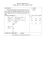
Function Block (FB), Function ID, Signal number
Function Block (FB) is the software module and GR-series IED implements FBs for
protections, controls and communications. The function ID is unique ID described by 6 digits
in hexadecimal; each function ID represents each FB. Signal number is the logical address of
the input and output data of the FB. The signal number (Data ID) consists of a function ID
and an element ID. The function ID is common within the FB; accordingly the element ID will
be shown to make description simple. The element ID is 10 hexadecimal and it has the
element ID name for easy to read. Figure 1.7-1 exemplifies the symbols, the function ID, and
the element ID. The table below shows the structure of the signal.
Function ID
Format
Element ID
FFFFFF (Hex)
Example
XXXXXXXXXX (Hex)
45A001
8000101C20
Element ID
FB (Function ID=45A001)
A
B
DIFL
C
Element ID
Signal name
800010EBB0
DIFZA_BLOCK
3. PLC connection point†
800101D11
8000101C20
&
8100101C21
≥1
DIFL AND
&
8200101C22
&
&
1
1. Relay element
2. Signal monitoring point
Figure 1.7-1 Example of symbols and others
†Note: In some scheme logic, the PLC connection point is presented as the function ID
plus element ID, which is shown in 16 delights in hexadecimal.
- 10 -