Giáo trình Xử lý tin hiệu số
Bạn đang xem bản rút gọn của tài liệu. Xem và tải ngay bản đầy đủ của tài liệu tại đây (7.3 MB, 838 trang )
Digital Signal
Processing
Tan: Digital Signaling Processing Perlims Final Proof page 1 23.6.2007 3:30am Compositor Name: MRaja
Tan: Digital Signaling Processing Perlims Final Proof page 2 23.6.2007 3:30am Compositor Name: MRaja
This page intentionally left blank
Digital Signal
Processing
Fundamentals and
Applications
Li Tan
DeVry University
Decatur, Georgia
AMSTERDAM • BOSTON • HEIDELBERG • LONDON
NEW YORK • OXFORD • PARIS • SAN DIEGO
SAN FRANCISCO • SINGAPORE • SYDNEY • TOKYO
Academic Press is an imprint of Elsevier
Tan: Digital Signaling Processing Perlims Final Proof page 3 23.6.2007 3:30am Compositor Name: MRaja
Academic Press is an imprint of Elsevier
30 Corporate Drive, Suite 400, Burlington, MA 01803, USA
525 B Street, Suite 1900, San Diego, California 92101-4495, USA
84 Theobald’s Road, London WC1X 8RR, UK
This book is printed on acid-free paper.
1
Copyright ß 2008, Elsevier Inc. All rights reserved.
No part of this publication may be reproduced or transmitted in any form or by any means,
electronic or mechanical, including photocopy, recording, or any information storage and
retrieval system, without permission in writing from the publisher.
Permissions may be sought directly from Elsevier’s Science & Technology Rights
Department in Oxford, UK: phone: (þ44) 1865 843830, fax: (þ44) 1865 853333,
E-mail: You may also complete your request on-line via
the Elsevier homepage (), by selecting ‘‘Support & Contact’’ then
‘‘Copyright and Permission’’ and then ‘‘Obtaining Permissions.’’
Library of Congress Cataloging-in-Publication Data
Application submitted.
British Library Cataloguing-in-Publication Data
A catalogue record for this book is available from the British Library.
ISBN: 978-0-12-374090-8
For information on all Academic Press publications
visit our Web site at www.books.elsevier.com
Printed in the United States of America
0708091011987654321
Tan: Digital Signaling Processing Perlims Final Proof page 4 23.6.2007 3:30am Compositor Name: MRaja
Contents
Preface xiii
About the Author xvii
1 Introduction to Digital Signal Processing 1
1.1 Basic Concepts of Digital Signal Processing 1
1.2 Basic Digital Signal Processing Examples in Block Diagrams 3
1.2.1 Digital Filtering 3
1.2.2 Signal Frequency (Spectrum) Analysis 4
1.3 Overview of Typical Digital Signal Processing in Real-World
Applications 6
1.3.1 Digital Crossover Audio System 6
1.3.2 Interference Cancellation in Electrocardiography 7
1.3.3 Speech Coding and Compression 7
1.3.4 Compact-Disc Recording System 9
1.3.5 Digital Photo Image Enhancement 10
1.4 Digital Signal Processing Applications 11
1.5 Summary 12
2 Signal Sampling and Quantization 13
2.1 Sampling of Continuous Signal 13
2.2 Signal Reconstruction 20
2.2.1 Practical Considerations for Signal Sampling:
Anti-Aliasing Filtering 25
2.2.2 Practical Considerations for Signal Reconstruction:
Anti-Image Filter and Equalizer 29
2.3 Analog-to-Digital Conversion, Digital-to-Analog
Conversion, and Quantization 35
2.4 Summary 49
2.5 MATLAB Programs 50
2.6 Problems 51
3 Digital Signals and Systems 57
3.1 Digital Signals 57
3.1.1 Common Digital Sequences 58
3.1.2 Generation of Digital Signals 62
Tan: Digital Signaling Processing Perlims Final Proof page 5 23.6.2007 3:30am Compositor Name: MRaja
3.2 Linear Time-Invariant, Causal Systems 64
3.2.1 Linearity 64
3.2.2 Time Invariance 65
3.2.3 Causality 67
3.3 Difference Equations and Impulse Responses 68
3.3.1 Format of Difference Equation 68
3.3.2 System Representation Using Its Impulse Response 69
3.4 Bounded-in-and-Bounded-out Stability 72
3.5 Digital Convolution 74
3.6 Summary 82
3.7 Problems 83
4 Discrete Fourier Transform and Signal Spectrum 87
4.1 Discrete Fourier Transform 87
4.1.1 Fourier Series Coefficients of Periodic Digital Signals 88
4.1.2 Discrete Fourier Transform Formulas 92
4.2 Amplitude Spectrum and Power Spectrum 98
4.3 Spectral Estimation Using Window Functions 110
4.4 Application to Speech Spectral Estimation 117
4.5 Fast Fourier Transform 120
4.5.1 Method of Decimation-in-Frequency 121
4.5.2 Method of Decimation-in-Time 127
4.6 Summary 131
4.7 Problems 131
5 The z-Transform 135
5.1 Definition 135
5.2 Properties of the z-Transform 139
5.3 Inverse z-Transform 142
5.3.1 Partial Fraction Expansion Using MATLAB 148
5.4 Solution of Difference Equations Using the z-Transform 151
5.5 Summary 155
5.6 Problems 156
6 Digital Signal Processing Systems, Basic Filtering Types,
and Digital Filter Realizations 159
6.1 The Difference Equation and Digital Filtering 159
6.2 Difference Equation and Transfer Function 165
6.2.1 Impulse Response, Step Response, and System Response 169
6.3 The z-Plane Pole-Zero Plot and Stability 171
6.4 Digital Filter Frequency Response 179
6.5 Basic Types of Filtering 188
Tan: Digital Signaling Processing Perlims Final Proof page 6 23.6.2007 3:30am Compositor Name: MRaja
vi CONTENTS
6.6 Realization of Digital Filters 195
6.6.1 Direct-Form I Realization 195
6.6.2 Direct-Form II Realization 196
6.6.3 Cascade (Series) Realization 197
6.6.4 Parallel Realization 198
6.7 Application: Speech Enhancement and Filtering 202
6.7.1 Pre-Emphasis of Speech 202
6.7.2 Bandpass Filtering of Speech 205
6.8 Summary 208
6.9 Problems 209
7 Finite Impulse Response Filter Design 215
7.1 Finite Impulse Response Filter Format 215
7.2 Fourier Transform Design 217
7.3 Window Method 229
7.4 Applications: Noise Reduction and
Two-Band Digital Crossover 253
7.4.1 Noise Reduction 253
7.4.2 Speech Noise Reduction 255
7.4.3 Two-Band Digital Crossover 256
7.5 Frequency Sampling Design Method 260
7.6 Optimal Design Method 268
7.7 Realization Structures of Finite Impulse Response Filters 280
7.7.1 Transversal Form 280
7.7.2 Linear Phase Form 282
7.8 Coefficient Accuracy Effects on Finite Impulse Response Filters 283
7.9 Summary of Finite Impulse Response (FIR) Design Procedures
and Selection of FIR Filter Design Methods in Practice 287
7.10 Summary 290
7.11 MATLAB Programs 291
7.12 Problems 294
8 Infinite Impulse Response Filter Design 303
8.1 Infinite Impulse Response Filter Format 303
8.2 Bilinear Transformation Design Method 305
8.2.1 Analog Filters Using Lowpass Prototype Transformation 306
8.2.2 Bilinear Transformation and Frequency Warping 310
8.2.3 Bilinear Transformation Design Procedure 317
8.3 Digital Butterworth and Chebyshev Filter Designs 322
8.3.1 Lowpass Prototype Function and Its Order 322
8.3.2 Lowpass and Highpass Filter Design Examples 326
8.3.3 Bandpass and Bandstop Filter Design Examples 336
Tan: Digital Signaling Processing Perlims Final Proof page 7 23.6.2007 3:30am Compositor Name: MRaja
CONTENTS vii
8.4 Higher-Order Infinite Impulse Response Filter Design
Using the Cascade Method 343
8.5 Application: Digital Audio Equalizer 346
8.6 Impulse Invariant Design Method 350
8.7 Polo-Zero Placement Method for Simple Infinite Impulse
Response Filters 358
8.7.1 Second-Order Bandpass Filter Design 359
8.7.2 Second-Order Bandstop (Notch) Filter Design 360
8.7.3 First-Order Lowpass Filter Design 362
8.7.4 First-Order Highpass Filter Design 364
8.8 Realization Structures of Infinite Impulse Response Filters 365
8.8.1 Realization of Infinite Impulse Response Filters in
Direct-Form I and Direct-Form II 366
8.8.2 Realization of Higher-Order Infinite Impulse
Response Filters via the Cascade Form 368
8.9 Application: 60-Hz Hum Eliminator and Heart Rate
Detection Using Electrocardiography 370
8.10 Coefficient Accuracy Effects on Infinite Impulse
Response Filters 377
8.11 Application: Generation and Detection of Dual-Tone
Multifrequency Tones Using Goertzel Algorithm 381
8.11.1 Single-Tone Generator 382
8.11.2 Dual-Tone Multifrequency Tone Generator 384
8.11.3 Goertzel Algorithm 386
8.11.4 Dual-Tone Multifrequency Tone Detection
Using the Modified Goertzel Algorithm 391
8.12 Summary of Infinite Impulse Response (IIR) Design
Procedures and Selection of the IIR Filter Design Methods
in Practice 396
8.13 Summary 401
8.14 Problems 402
9 Hardware and Software for Digital Signal Processors 413
9.1 Digital Signal Processor Architecture 413
9.2 Digital Signal Processor Hardware Units 416
9.2.1 Multiplier and Accumulator 416
9.2.2 Shifters 417
9.2.3 Address Generators 418
9.3 Digital Signal Processors and Manufactures 419
9.4 Fixed-Point and Floating-Point Formats 420
9.4.1 Fixed-Point Format 420
9.4.2 Floating-Point Format 429
9.4.3 IEEE Floating-Point Formats 434
Tan: Digital Signaling Processing Perlims Final Proof page 8 23.6.2007 3:30am Compositor Name: MRaja
viii C O N T E N T S
9.4.5 Fixed-Point Digital Signal Processors 437
9.4.6 Floating-Point Processors 439
9.5 Finite Impulse Response and Infinite Impulse Response
Filter Implementation in Fixed-Point Systems 441
9.6 Digital Signal Processing Programming Examples 447
9.6.1 Overview of TMS320C67x DSK 447
9.6.2 Concept of Real-Time Processing 451
9.6.3 Linear Buffering 452
9.6.4 Sample C Programs 455
9.7 Summary 460
9.8 Problems 461
10 Adaptive Filters and Applications 463
10.1 Introduction to Least Mean Square Adaptive Finite
Impulse Response Filters 463
10.2 Basic Wiener Filter Theory and Least Mean Square Algorithm 467
10.3 Applications: Noise Cancellation, System Modeling,
and Line Enhancement 473
10.3.1 Noise Cancellation 473
10.3.2 System Modeling 479
10.3.3 Line Enhancement Using Linear Prediction 484
10.4 Other Application Examples 486
10.4.1 Canceling Periodic Interferences Using
Linear Prediction 487
10.4.2 Electrocardiography Interference Cancellation 488
10.4.3 Echo Cancellation in Long-Distance
Telephone Circuits 489
10.5 Summary 491
10.6 Problems 491
11 Waveform Quantization and Compression 497
11.1 Linear Midtread Quantization 497
11.2 m-law Companding 501
11.2.1 Analog m-Law Companding 501
11.2.2 Digital m-Law Companding 506
11.3 Examples of Differential Pulse Code Modulation (DPCM),
Delta Modulation, and Adaptive DPCM G.721 510
11.3.1 Examples of Differential Pulse Code Modulation
and Delta Modulation 510
11.3.2 Adaptive Differential Pulse Code Modulation G.721 515
11.4 Discrete Cosine Transform, Modified Discrete Cosine
Transform, and Transform Coding in MPEG Audio 522
11.4.1 Discrete Cosine Transform 522
Tan: Digital Signaling Processing Perlims Final Proof page 9 23.6.2007 3:30am Compositor Name: MRaja
CONTENTS ix
11.4.2 Modified Discrete Cosine Transform 525
11.4.3 Transform Coding in MPEG Audio 530
11.5 Summary 533
11.6 MATLAB Programs 534
11.7 Problems 550
12 Multirate Digital Signal Processing, Oversampling of
Analog-to-Digital Conversion, and Undersampling of
Bandpass Signals 557
12.1 Multirate Digital Signal Processing Basics 557
12.1.1 Sampling Rate Reduction by an Integer Factor 558
12.1.2 Sampling Rate Increase by an Integer Factor 564
12.1.3 Changing Sampling Rate by a Non-Integer Factor L/M 570
12.1.4 Application: CD Audio Player 575
12.1.5 Multistage Decimation 578
12.2 Polyphase Filter Structure and Implementation 583
12.3 Oversampling of Analog-to-Digital Conversion 589
12.3.1 Oversampling and Analog-to-Digital Conversion
Resolution 590
12.3.2 Sigma-Delta Modulation Analog-to-Digital Conversion 593
12.4 Application Example: CD Player 599
12.5 Undersampling of Bandpass Signals 601
12.6 Summary 609
12.7 Problems 610
13 Image Processing Basics 617
13.1 Image Processing Notation and Data Formats 617
13.1.1 8-Bit Gray Level Images 618
13.1.2 24-Bit Color Images 619
13.1.3 8-Bit Color Images 620
13.1.4 Intensity Images 621
13.1.5 Red, Green, Blue Components and Grayscale
Conversion 622
13.1.6 MATLAB Functions for Format Conversion 624
13.2 Image Histogram and Equalization 625
13.2.1 Grayscale Histogram and Equalization 625
13.2.2 24-Bit Color Image Equalization 632
13.2.3 8-Bit Indexed Color Image Equalization 633
13.2.4 MATLAB Functions for Equalization 636
13.3 Image Level Adjustment and Contrast 637
13.3.1 Linear Level Adjustment 638
13.3.2 Adjusting the Level for Display 641
Tan: Digital Signaling Processing Perlims Final Proof page 10 23.6.2007 3:30am Compositor Name: MRaja
x CONTENTS
13.3.3 Matlab Functions for Image Level Adjustment 642
13.4 Image Filtering Enhancement 642
13.4.1 Lowpass Noise Filtering 643
13.4.2 Median Filtering 646
13.4.3 Edge Detection 651
13.4.4 MATLAB Functions for Image Filtering 655
13.5 Image Pseudo-Color Generation and Detection 657
13.6 Image Spectra 661
13.7 Image Compression by Discrete Cosine Transform 664
13.7.1 Two-Dimensional Discrete Cosine Transform 666
13.7.2 Two-Dimensional JPEG Grayscale Image
Compression Example 669
13.7.3 JPEG Color Image Compression 671
13.8 Creating a Video Sequence by Mixing Two Images 677
13.9 Video Signal Basics 677
13.9.1 Analog Video 678
13.9.2 Digital Video 685
13.10 Motion Estimation in Video 687
13.11 Summary 690
13.12 Problems 692
Appendix A Introduction to the MATLAB Environment 699
A.1 Basic Commands and Syntax 699
A.2 MATLAB Array and Indexing 703
A.3 Plot Utilities: Subplot, Plot, Stem, and Stair 704
A.4 MATLAB Script Files 704
A.5 MATLAB Functions 705
Appendix B Review of Analog Signal Processing Basics 709
B.1 Fourier Series and Fourier Transform 709
B.1.1 Sine-Cosine Form 709
B.1.2 Amplitude-Phase Form 710
B.1.3 Complex Exponential Form 711
B.1.4 Spectral Plots 714
B.1.5 Fourier Transform 721
B.2 Laplace Transform 726
B.2.1 Laplace Transform and Its Table 726
B.2.2 Solving Differential Equations Using
Laplace Transform 727
B.2.3 Transfer Function 730
B.3 Poles, Zeros, Stability, Convolution, and Sinusoidal
Steady-State Response 731
Tan: Digital Signaling Processing Perlims Final Proof page 11 23.6.2007 3:30am Compositor Name: MRaja
CONTENTS xi
B.3.1 Poles, Zeros, and Stability 731
B.3.2 Convolution 733
B.3.3 Sinusoidal Steady-State Response 735
B.4 Problems 736
Appendix C Normalized Butterworth and Chebyshev Fucntions 741
C.1 Normalized Butterworth Function 741
C.2 Normalized Chebyshev Function 744
Appendix D Sinusoidal Steady-State Response of Digital Filters 749
D.1 Sinusoidal Steady-State Response 749
D.2 Properties of the Sinusoidal Steady-State Response 751
Appendix E Finite Impulse Response Filter Design Equations by the
Frequency Sampling Design Method 753
Appendix F Some Useful Mathematical Formulas 757
Bibliography 761
Answers to Selected Problems 765
Index 791
Tan: Digital Signaling Processing Perlims Final Proof page 12 23.6.2007 3:30am Compositor Name: MRaja
xii C O N T E N T S
Preface
Technologies such as microprocessors, microcontrollers, and digital signal pro-
cessors have become so advanced that they have had a dramatic impact on the
disciplines of electronics engineering, computer engineering, and biomedical
engineering. Technologists need to become familiar with digital signals and
systems and basic digital signal processing (DSP) techniques. The objective of
this book is to introduce students to the fundamental principles of these subjects
and to provide a working knowledge such that they can apply DSP in their
engineering careers.
The book is suitable for a sequence of two-semester courses at the senior level
in undergraduate electronics, computer, and biomedical engineering technology
programs. Chapters 1 to 8 provide the topics for a one semester course, and a
second course can complete the rest of the chapters. This textbook can also be
used in an introductory DSP course at the junior level in undergraduate elec-
trical engineering programs at traditional colleges. Additionally, the book
should be useful as a reference for undergraduate engineering students, science
students, and practicing engineers.
The material has been tested in two consecutive courses in signal processing
sequence at DeVry University on the Decatur campus in Georgia. With the
background established from this book, students can be well prepared to move
forward to take other senior-level courses that deal with digital signals and
systems for communications and controls.
The textbook consists of 13 chapters, organized as follows:
&
Chapter 1 introduces concepts of DSP and presents a general DSP block
diagram. Application examples are included.
&
Chapter 2 covers the sampling theorem described in time domain and
frequency domain and also covers signal reconstruction. Some practical
considerations for designing analog anti-aliasing lowpass filters and anti-
image lowpass filters are included. The chapter ends with a section dealing
with analog-to-digital conversion (ADC) and digital-to-analog conversion
(DAC), as well as signal quantization and encoding.
&
Chapter 3 introduces digital signals, linear time-invariant system concepts,
difference equations, and digital convolutions.
Tan: Digital Signaling Processing Perlims Final Proof page 13 23.6.2007 3:30am Compositor Name: MRaja
&
Chapter 4 introduces the discrete Fourier transform (DFT) and digital
signal spectral calculations using the DFT. Applying the DFT to estimate
the speech spectrum is demonstrated. The chapter ends with a section
dedicated to illustrating fast Fourier transform (FFT) algorithms.
&
Chapter 5 is devoted to the z-transform and difference equations.
&
Chapter 6 covers digital filtering using difference equations, transfer func-
tions, system stability, digital filter frequency responses, and implementa-
tion methods such as the direct form I and direct form II.
&
Chapter 7 deals with various methods of finite impulse response (FIR)
filter design, including the Fourier transform method for calculating FIR
filter coefficients, window method, frequency sampling design, and optimal
design. Chapter 7 also includes applications using FIR filters for noise
reduction and digital crossover system design.
&
Chapter 8 covers various methods of infinite impulse response (IIR) filter
design, including the bilinear transformation (BLT) design, impulse invari-
ant design, and pole-zero placement design. Applications using IIR filters
include audio equalizer design, biomedical signal enhancement, dual-tone
multifrequency (DTMF) tone generation and detection with the Goertzel
algorithm.
&
Chapter 9 introduces DSP architectures, software and hardware, and
fixed-point and floating-point implementations of digital filters.
&
Chapter 10 covers adaptive filters with applications such as noise cancel-
lation, system modeling, line enhancement, cancellation of periodic inter-
ferences, echo cancellation, and 60-Hz interference cancellation in
biomedical signals.
&
Chapter 11 is devoted to speech quantization and compression, including
pulse code modulation (PCM) coding, mu-law compression, adaptive dif-
ferential pulse code modulation (ADPCM) coding, windowed modified
discrete cosine transform (W-MDCT) coding, and MPEG audio format,
specifically MP3 (MPEG-1, layer 3).
&
Chapter 12 covers topics pertaining to multirate DSP and applications, as
well as principles of oversampling ADC, such as sigma-delta modulation.
Undersampling for bandpass signals is also examined.
&
Finally, Chapter 13 covers image enhancement using histogram equaliza-
tion and filtering methods, including edge detection. The chapter also
explores pseudo-color image generation and detection, two-dimensional
spectra, JPEG compression using DCT, and the mixing of two images to
Tan: Digital Signaling Processing Perlims Final Proof page 14 23.6.2007 3:30am Compositor Name: MRaja
xiv P R E F A C E
create a video sequence. Finally, motion compensation of the video sequence
is explored, which is a key element of video compression used in MPEG.
MATLAB programs are listed wherever they are possible. Therefore, a
MATLAB tutorial should be given to students who are new to the MATLAB
environment.
&
Appendix A serves as a MATLAB tutorial.
&
Appendix B reviews key fundamentals of analog signal processing. Topics
include Fourier series, Fourier transform, Laplace transform, and analog
system basics.
&
Appendixes C, D, and E overview Butterworth and Chebyshev filters,
sinusoidal steady-state responses in digital filters, and derivation of the
FIR filter design equation via the frequency sampling method, respectively.
&
Appendix F offers general useful mathematical formulas.
Instructor support, including solutions, can be found at http://textbooks.
elsevier.com. MATLAB programs and exercises for students, plus Real-
time C programs, can be found at />9780123740908.
The author wishes to thank Dr. Samuel D. Stearns (professor at the Univer-
sity of New Mexico; Sandia National Laboratories, Albuquerque, NM),
Dr. Delores M. Etler (professor at the United States Naval Academy at
Annapolis, MD) and Dr. Neeraj Magotra (Texas Instruments, former professor
at the University of New Mexico) for inspiration, guidance, and sharing of
their insight into DSP over the years. A special thanks goes to Dr. Jean Jiang
(professor at DeVry University in Decatur) for her encouragement, support,
insightful suggestions, and testing of the manuscript in her DSP course.
Special thanks go to Tim Pitts (senior commissioning editor), Rick Adams
(senior acquistions editor), and Rachel Roumeliotis (acquisitions editor) and to
the team members at Elsevier Science publishing for their encouragement and
guidance in developing the complete manuscript.
I also wish to thank Jamey Stegmaier (publishing project manager) at SPi for
coordinating the copyediting of the manuscript.
Thanks to all the faculty and staff at DeVry University, Decatur, for their
encouragement and support.
The book has benefited from many constructive comments and suggestions
from the following reviewers and anonymous reviewers. The author takes this
opportunity to thank them for their significant contributions:
Professor Mateo Aboy, Oregon Institute of Technology, Klamath Falls, OR
Professor Jean Andrian, Florida International University, Miami, FL
Professor Rabah Aoufi, DeVry University, Irving, TX
Professor Larry Bland, John Brown University, Siloam Springs, AR
Tan: Digital Signaling Processing Perlims Final Proof page 15 23.6.2007 3:30am Compositor Name: MRaja
PREFACE xv
Professor Phillip L. De Leon, New Mexico State University, Las Cruces, NM
Professor Mohammed Feknous, New Jersey Institute of Technology, Newark, NJ
Professor Richard L. Henderson, DeVry University, Kansas City, MO
Professor Ling Hou, St. Cloud State University, St. Cloud, MN
Professor Robert C. (Rob) Maher, Montana State University, Bozeman, MT
Professor Abdulmagid Omar, DeVry University, Tinley Park, IL
Professor Ravi P. Ramachandran, Rowan University, Glassboro, NJ
Professor William (Bill) Routt, Wake Technical Community College, Raleigh, NC
Professor Samuel D. Stearns, University of New Mexico; Sandia National Laboratories,
Albuquerque, NM
Professor Les Thede, Ohio Northern University, Ada, OH
Professor Igor Tsukerman, University of Akron, Akron, OH
Professor Vijay Vaidyanathan, University of North Texas, Denton, TX
Professor David Waldo, Oklahoma Christian University, Oklahoma City, OK
Finally, I am immensely grateful to my wife, Jean, and my children, Ava,
Alex, and Amber, for their extraordinary patience and understanding during the
entire preparation of this book.
Li Tan
DeVry University
Decatur, Georgia
May 2007
Tan: Digital Signaling Processing Perlims Final Proof page 16 23.6.2007 3:30am Compositor Name: MRaja
xvi P R E F A C E
About the Author
Dr. Li Tan is a Professor of Electronics Engineering Technology at DeVry
University, Decatur, Georgia. He received his M.S. and Ph.D. degrees in Elec-
trical Engineering from the University of New Mexico. He has extensively
taught analog and digital signal processing and analog and digital communica-
tions for many years. Before teaching at DeVry University, Dr. Tan worked in
the DSP and communications industry.
Dr. Tan is a senior member of the Institute of Electronic and Electronic
Engineers (IEEE). His principal technical areas include digital signal processing,
adaptive signal processing, and digital communications. He has published a
number of papers in these areas.
Tan: Digital Signaling Processing Perlims Final Proof page 17 23.6.2007 3:30am Compositor Name: MRaja
1
Introduction to Digital Signal
Processing
Objectives:
This chapter introduces concepts of digital signal processing (DSP) and reviews
an overall picture of its applications. Illustrative application examples include
digital noise filtering, signal frequency analysis, speech and audio compression,
biomedical signal processing such as interference cancellation in electrocardiog-
raphy, compact-disc recording, and image enhancement.
1.1 Basic Concepts of Digital Signal
Processing
Digital signal processing (DSP) technology and its advancements have dramat-
ically impacted our modern society everywhere. Without DSP, we would not
have digital/Internet audio or video; digital recording; CD, DVD, and MP3
players; digital cameras; digital and cellular telephones; digital satellite and TV;
or wire and wireless networks. Medical instruments would be less efficient or
unable to provide useful information for precise diagnoses if there were no
digital electrocardiography (ECG) analyzers or digital x-rays and medical
image systems. We would also live in many less efficient ways, since we would
not be equipped with voice recognition systems, speech synthesis systems, and
image and video editing systems. Without DSP, scientists, engineers, and tech-
nologists would have no powerful tools to analyze and visualize data and
perform their design, and so on.
Tan: Digital Signaling Processing 0123740908_chap01 Final Proof page 1 22.6.2007 3:22pm Compositor Name: Mraja
The concept of DSP is illustrated by the simplified block diagram in
Figure 1.1, which consists of an analog filter, an analog-to-digital conversion
(ADC) unit, a digital signal (DS) processor, a digital-to-analog conversion
(DAC) unit, and a reconstruction (anti-image) filter.
As shown in the diagram, the analog input signal, which is continuous in
time and amplitude, is generally encountered in our real life. Examples of such
analog signals include current, voltage, temperature, pressure, and light inten-
sity. Usually a transducer (sensor) is used to convert the nonelectrical signal to
the analog electrical signal (voltage). This analog signal is fed to an analog filter,
which is applied to limit the frequency range of analog signals prior to the
sampling process. The purpose of filtering is to significantly attenuate aliasing
distortion, which will be explained in the next chapter. The band-limited signal
at the output of the analog filter is then sampled and converted via the ADC
unit into the digital signal, which is discrete both in time and in amplitude. The
DS processor then accepts the digital signal and processes the digital data
according to DSP rules such as lowpass, highpass, and bandpass digital filtering,
or other algorithms for different applications. Notice that the DS processor
unit is a special type of digital computer and can be a general-purpose digital
computer, a microprocessor, or an advanced microcontroller; furthermore, DSP
rules can be implemented using software in general.
With the DS processor and corresponding software, a processed digital
output signal is generated. This signal behaves in a manner according to the
specific algorithm used. The next block in Figure 1.1, the DAC unit, converts
the processed digital signal to an analog output signal. As shown, the signal is
continuous in time and discrete in amplitude (usually a sample-and-hold signal,
to be discussed in Chapter 2). The final block in Figure 1.1 is designated as
a function to smooth the DAC output voltage levels back to the analog signal
via a reconstruction (anti-image) filter for real-world applications.
In general, the analog signal process does not require software, an algorithm,
ADC, and DAC. The processing relies wholly on electrical and electronic
devices such as resistors, capacitors, transistors, operational amplifiers, and
integrated circuits (ICs).
DSP systems, on the other hand, use software, digital processing, and algo-
rithms; thus they have a great deal of flexibility, less noise interference, and no
Analog
filter
ADC
DS
processor
DAC
Reconstruction
filter
Analog
input
Analog
output
Band-limited
signal
Digital
signal
Processed
digital signal
Output
signal
F IG UR E 1 .1 A digital signal processing scheme.
Tan: Digital Signaling Processing 0123740908_chap01 Final Proof page 2 22.6.2007 3:22pm Compositor Name: Mraja
2 1 INTRODUCTION TO DIGITAL SIGNAL PROCESSING
signal distortion in various applications. However, as shown in Figure 1.1, DSP
systems still require minimum analog processing such as the anti-aliasing and
reconstruction filters, which are musts for converting real-world information
into digital form and digital form back into real-world information.
Note that there are many real-world DSP applications that do not require
DAC, such as data acquisition and digital information display, speech recogni-
tion, data encoding, and so on. Similarly, DSP applications that need no ADC
include CD players, text-to-speech synthesis, and digital tone generators, among
others. We will review some of them in the following sections.
1.2 Basic Digital Signal Processing
Examples in Block Diagrams
We first look at digital noise filtering and signal frequency analysis, using block
diagrams.
1.2.1 Digital Filtering
Let us consider the situation shown in Figure 1.2, depicting a digitized noisy
signal obtained from digitizing analog voltages (sensor output) containing
a useful low-frequency signal and noise that occupies all of the frequency
range. After ADC, the digitized noisy signal x(n), where n is the sample number,
can be enhanced using digital filtering.
Since our useful signal contains the low-frequency component, the high-
frequency components above that of our useful signal are considered as noise,
which can be removed by using a digital lowpass filter. We set up the DSP block
in Figure 1.2 to operate as a simple digital lowpass filter. After processing the
digitized noisy signal x(n), the digital lowpass filter produces a clean digital
signal y(n). We can apply the cleaned signal y(n) to another DSP algorithm for a
different application or convert it to the analog signal via DAC and the recon-
struction filter.
The digitized noisy signal and clean digital signal, respectively, are plotted in
Figure 1.3, where the top plot shows the digitized noisy signal, while the bottom
plot demonstrates the clean digital signal obtained by applying the digital low-
pass filter. Typical applications of noise filtering include acquisition of clean
DSP
Digital filtering
x (n) y (n)
Digitized noisy input Clean digital signal
F I GU RE 1 . 2 The simple digital filtering block.
Tan: Digital Signaling Processing 0123740908_chap01 Final Proof page 3 22.6.2007 3:22pm Compositor Name: Mraja
1.2 Basic Digital Signal Processing Examples in Block Diagrams 3
digital audio and biomedical signals and enhancement of speech recording,
among others (Embree, 1995; Rabiner and Schafer, 1978; Webster, 1998).
1.2.2 Signal Frequency (Spectrum) Analysis
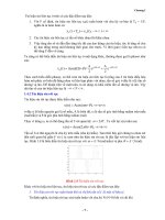
As shown in Figure 1.4, certain DSP applications often require that time domain
information and the frequency content of the signal be analyzed. Figure 1.5
shows a digitized audio signal and its calculated signal spectrum (frequency
content), defined as the signal amplitude versus its corresponding frequency for
the time being via a DSP algorithm, called fast Fourier transform (FFT), which
will be studied in Chapter 4. The plot in Figure 1.5 (a) is a time domain display
of the recorded audio signal with a frequency of 1,000 Hz sampled at 16,000
samples per second, while the frequency content display of plot (b) displays the
calculated signal spectrum versus frequencies, in which the peak amplitude is
clearly located at 1,000 Hz. Plot (c) shows a time domain display of an audio
signal consisting of one signal of 1,000 Hz and another of 3,000 Hz sampled at
16,000 samples per second. The frequency content display shown in Plot (d)
0 0.005 0.01 0.015 0.02 0.025 0.03
−2
−1
0
1
2
Noisy signal
Amplitude
0 0.005 0.01 0.015 0.02 0.025 0.03
−2
−1
0
1
2
Amplitude
Time (sec)
Time (sec)
Clean signal
FIGURE 1.3 (
Top
) Digitized noisy signal. (
Bottom
) Clean digital signal using the digital
lowpass filter.
Tan: Digital Signaling Processing 0123740908_chap01 Final Proof page 4 22.6.2007 3:22pm Compositor Name: Mraja
4 1 INTRODUCTION TO DIGITAL SIGNAL PROCESSING
gives two locations (1,000 Hz and 3,000 Hz) where the peak amplitudes reside,
hence the frequency content display presents clear frequency information of the
recorded audio signal.
As another practical example, we often perform spectral estimation of a
digitally recorded speech or audio (music) waveform using the FFT algorithm
in order to investigate spectral frequency details of speech information. Figure
1.6 shows a speech signal produced by a human in the time domain and
frequency content displays. The top plot shows the digital speech waveform
versus its digitized sample number, while the bottom plot shows the frequency
content information of speech for a range from 0 to 4,000 Hz. We can observe
that there are about ten spectral peaks, called speech formants, in the range
between 0 and 1,500 Hz. Those identified speech formants can be used for
Analog
filter
ADC
DSP
algorithms
Time domain display
x(n)
Analog
input
Frequency content display
F I GU RE 1 . 4 Signal spectral analysis.
0 0.005 0.01
−5
0
5
Time (sec)
A
CD
B
Signal amplitude
0 0.005 0.01
−10
−5
0
5
10
Time (sec)
Signal amplitude
0 2000 4000 6000 8000
0
2
4
6
Frequency (Hz)
Signal spectrum
0 2000 4000 6000 8000
0
2
4
6
Frequency (Hz)
Signal spectrum
1000 Hz
1000 Hz
3000 Hz
F I GU RE 1 . 5 Audio signals and their spectrums.
Tan: Digital Signaling Processing 0123740908_chap01 Final Proof page 5 22.6.2007 3:22pm Compositor Name: Mraja
1.2 Basic Digital Signal Processing Examples in Block Diagrams 5
applications such as speech modeling, speech coding, speech feature extraction
for speech synthesis and recognition, and so on (Deller et al., 1993).
1.3 Overview of Typical Digital Signal
Processing in Real-World
Applications
1.3.1 Digital Crossover Audio System
An audio system is required to operate in an entire audible range of frequen-
cies, which may be beyond the capability of any single speaker driver. Several
drivers, such as the speaker cones and horns, each covering a different frequency
range, are used to cover the full audio frequency range.
Figure 1.7 shows a typical two-band digital crossover system consisting of
two speaker drivers: a woofer and a tweeter. The woofer responds to low
frequencies, while the tweeter responds to high frequencies. The incoming digital
audio signal is split into two bands by using a digital lowpass filter and a digital
highpass filter in parallel. Then the separated audio signals are amplified.
Finally, they are sent to their corresponding speaker drivers. Although the
0 0.2 0.4 0.6 0.8 1 1.2 1.4 1.6 1.8 2
ϫ10
4
−2
−1
0
1
2
ϫ10
4
Speech data: We lost the golden chain.
Sample number
Speech amplitude
0 500 1000 1500 2000 2500 3000 3500 4000
0
100
200
300
400
Frequency (Hz)
Amplitude spectrum
F I GU RE 1 . 6 Speech sample and speech spectrum.
Tan: Digital Signaling Processing 0123740908_chap01 Final Proof page 6 22.6.2007 3:22pm Compositor Name: Mraja
6 1 INTRODUCTION TO DIGITAL SIGNAL PROCESSING
traditional crossover systems are designed using the analog circuits, the digital
crossover system offers a cost-effective solution with programmable ability,
flexibility, and high quality. This topic is taken up in Chapter 7.
1.3.2 Interference Cancellation in
Electrocardiography
In ECG recording, there often is unwanted 60-Hz interference in the recorded
data (Webster, 1998). The analysis shows that the interference comes from
the power line and includes magnetic induction, displacement currents in leads
or in the body of the patient, effects from equipment interconnections, and
other imperfections. Although using proper grounding or twisted pairs minim-
izes such 60-Hz effects, another effective choice can be use of a digital notch
filter, which eliminates the 60-Hz interference while keeping all the other useful
information. Figure 1.8 illustrates a 60-Hz interference eliminator using a
digital notch filter. With such enhanced ECG recording, doctors in clinics
can give accurate diagnoses for patients. This technique can also be applied
to remove 60-Hz interferences in audio systems. This topic is explored in depth
in Chapter 8.
1.3.3 Speech Coding and Compression
One of the speech coding methods, called waveform coding, is depicted in
Figure 1.9(a), describing the encoding process, while Figure 1.9(b) shows the
decoding process. As shown in Figure 1.9(a), the analog signal is first filtered by
analog lowpass to remove high-frequency noise components and is then passed
through the ADC unit, where the digital values at sampling instants are cap-
tured by the DS processor. Next, the captured data are compressed using data
compression rules to save the storage requirement. Finally, the compressed
digital information is sent to storage media. The compressed digital information
Digital
audio x(n)
Digital
highpass filter
Digital
lowpass filter
Gain
Gain
Tweeter:
The crossover passes
high frequencies
Woofer:
The crossover passes
low frequencies
F I GU RE 1 . 7 Two-band digital crossover.
Tan: Digital Signaling Processing 0123740908_chap01 Final Proof page 7 22.6.2007 3:22pm Compositor Name: Mraja
1.3 Overview of Typical Digital Signal Processing in Real-World Applications 7