Toyota camry 2006 2011 2AZ FE lubrication hệ thống bôi trơn xe toyota camry 2AZ FE đời 2006 2011
Bạn đang xem bản rút gọn của tài liệu. Xem và tải ngay bản đầy đủ của tài liệu tại đây (1.38 MB, 22 trang )
2AZ-FE LUBRICATION – LUBRICATION SYSTEM
LU–1
LU
LUBRICATION SYSTEM
ON-VEHICLE INSPECTION
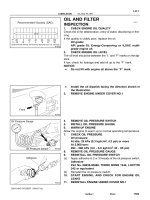
1. CHECK ENGINE OIL LEVEL
(a) Warm up the engine, stop the engine and wait for 5
minutes.
(b) Check that the engine oil level is between the L and
F marks of the oil dipstick.
If low, check for leakage and add oil up to the F
mark.
NOTICE:
Do not add engine oil above the F mark.
2. CHECK ENGINE OIL QUALITY
(a) Check the oil for deterioration, water intrusion,
discoloration or thinning.
If the quality is visibly poor, replace the oil.
Oil grade:
Use ILSAC multigrade engine oil. SAE 5W-20
and SAE 0W-20 engine oil may be used.
However, SAE 0W-20 is the best choice for
good fuel economy and good starting in cold
weather.
3. CHECK OIL PRESSURE
(a) Disconnect the oil pressure switch connector.
(b) Using a 24 mm deep socket wrench, remove the oil
pressure switch.
(c) Install the oil pressure gauge.
(d) Warm up the engine.
(e) Measure the oil pressure.
Standard oil pressure
Recommended Viscosity (SAE)
5W-20, 0W-20
°C
°F
-29
-20
-18 -7 4 16 27 38
0 20 40 60 80 100
A066623E18
A112272
Oil Pressure Gauge
A112273E01
Condition Specified Condition
Idle
29 kPa (0.3 kgf/cm
2
, 4.3 psi) or more
3,000 rpm
170 to 300 kPa (1.7 to 3.1 kgf/cm
2
, 24
to 44 psi)
LU–2
2AZ-FE LUBRICATION – LUBRICATION SYSTEM
LU
(f) Apply adhesive to 2 or 3 threads of the oil pressure
switch.
Adhesive:
Toyota Genuine Adhesive 1344, Three Bond
1344 or Equivalent
(g) Using a 24 mm deep socket wrench, install the oil
pressure switch.
Torque: 15 N*m (153 kgf*cm, 11 ft.*lbf)
NOTICE:
Do not start the engine within 1 hour of
installation.
(h) Connect the oil pressure switch connector.
(i) Check for engine oil leaks.
Adhesive
A085603E02
2AZ-FE LUBRICATION – OIL FILTER
LU–3
LU
ENGINE2AZ-FE LUBRICATION
OIL FILTER
COMPONENTS
N*m (kgf*cm, ft.*lbf)
: Specified torque
OIL FILTER SUB-ASSEMBLY
Non-reusable part
13 (133, 10)
A134971E01
LU–4
2AZ-FE LUBRICATION – OIL FILTER
LU
REPLACEMENT
CAUTION:
• Prolonged and repeated contact with engine oil will
cause the loss of natural oils from the skin, leading to
dryness, irritation and dermatitis. In addition, used
engine oil contains potentially harmful contaminants
which may cause skin cancer.
• Precautions should be taken when replacing engine
oil to minimize the risk of your skin making contact
with used engine oil. Wear protective clothing and
gloves. Wash your skin thoroughly with soap and
water, or use a waterless hand cleaner to remove any
used engine oil. Do not use gasoline, thinners or
solvents.
• For environmental protection, used oil and used oil
filters must be disposed of at designated disposal
sites.
1. DRAIN ENGINE OIL
(a) Remove the oil filler cap.
(b) Remove the oil drain plug and drain the oil into a
container.
2. REMOVE OIL FILTER SUB-ASSEMBLY
(a) Using SST, remove the oil filter.
SST 09228-06501
3. INSTALL OIL FILTER SUB-ASSEMBLY
(a) Check and clean the oil filter installation surface.
(b) Apply clean engine oil to the gasket of a new oil
filter.
(c) Lightly screw the oil filter into place by hand. Tighten
it until the gasket contacts the seat.
(d) Using SST, tighten the oil filter.
SST 09228-06501
(1) Depending on the work space available,
choose from the following.
1. If enough space is available, use a torque
wrench to tighten the oil filter.
Torque: 13 N*m (133 kgf*cm, 10 ft.*lbf)
2. If enough space is not available to use a
torque wrench, tighten the oil filter a 3/4 turn by
hand or use a common wrench.
4. ADD ENGINE OIL
(a) Clean and install the oil drain plug with a new
gasket.
Torque: 25 N*m (255 kgf*cm, 18 ft.*lbf)
(b) Add new oil.
Standard capacity
SST
A136225E01
SST
A136227E01
Item Standard Condition
Drain and refill with oil filter change 4.3 liters (4.5 US qts, 3.8 Imp. qts)
2AZ-FE LUBRICATION – OIL FILTER
LU–5
LU
(c) Install the oil filler cap.
5. CHECK FOR ENGINE OIL LEAKS
Drain and refill without oil filter
change
4.1 liters (4.3 US qts, 3.6 Imp. qts)
Dry fill 5.0 liters (5.3 US qts, 4.4 Imp. qts)
Item Standard Condition
2AZ-FE LUBRICATION – OIL PUMP
LU–5
LU
ENGINE2AZ-FE LUBRICATION
OIL PUMP
COMPONENTS
FRONT FENDER APRON SEAL RH
N*m (kgf*cm, ft.*lbf)
: Specified torque
ENGINE MOVING CONTROL ROD SUB-ASSEMBLY
NO. 1 ENGINE COVER SUB-ASSEMBLY
NO. 2 ENGINE MOUNTING BRACKET RH
NO. 2 ENGINE MOUNTING STAY RH
V-RIBBED BELT
64 (653, 47)
64 (653, 47)
52 (531, 38)
52 (531, 38)
21 (214, 15)
9.0 (92, 80 in.*lbf)
9.8 (100, 87 in.*lbf)
GENERATOR ASSEMBLY
A134948E01
LU–6
2AZ-FE LUBRICATION – OIL PUMP
LU
ENGINE UNDER COVER RH
ENGINE UNDER COVER LH
N*m (kgf*cm, ft.*lbf)
: Specified torque
Non-reusable part
VANE PUMP ASSEMBLY
43 (439, 32)
FRONT EXHAUST
PIPE ASSEMBLY
EXHAUST PIPE GASKET
EXHAUST PIPE GASKET
FRONT EXHAUST PIPE NO. 1
SUPPORT BRACKET
62 (633, 46)
33 (337, 24)
33 (337, 24)
56 (571, 41)
REAR EXHAUST PIPE NO. 1
SUPPORT BRACKET
A134947E01
2AZ-FE LUBRICATION – OIL PUMP
LU–7
LU
CRANKSHAFT PULLEY
CYLINDER HEAD COVER SUB-ASSEMBLY
IGNITION COIL ASSEMBLY
N*m (kgf*cm, ft.*lbf)
: Specified torque
Non-reusable part
9.0 (92, 80 in.*lbf)
9.0 (92, 80 in.*lbf)
9.0 (92, 80 in.*lbf)
9.0 (92, 80 in.*lbf)
TMMK: 170 (1,733, 125)
TMC: 180 (1,835, 133)
25 (255, 18)
11 (110, 8)
CYLINDER HEAD COVER GASKET
x12
x2
GASKET
OIL PAN DRAIN PLUG
OIL PAN SUB-ASSEMBLY
CRANK POSITION
SENSOR
11 (110, 8)
14 (143, 10)
14 (143, 10)
x2
x6
A134922E01
LU–8
2AZ-FE LUBRICATION – OIL PUMP
LU
N*m (kgf*cm, ft.*lbf)
: Specified torque
Non-reusable part
GASKET
GASKET
TIMING CHAIN
CASE OIL SEAL
9.0 (92, 80 in.*lbf)
9.0 (92, 80 in.*lbf)
9.0 (92, 80 in.*lbf)
19 (194, 14)
30 (301, 22)
19 (194, 14)
55 (561, 44)
25 (255, 18)
60 (607, 44)
12 (122, 9.0)
CHAIN SUB-ASSEMBLY
CHAIN TENSIONER
SLIPPER
NO. 1 CHAIN VIBRATION DAMPER
NO. 2 CHAIN SUB-ASSEMBLY
V-RIBBED BELT
TENSIONER
ASSEMBLY
OIL PUMP DRIVE SPROCKET
SPRING
CHAIN TENSIONER PLATE
OIL PUMP DRIVEN
SPROCKET
OIL PUMP ASSEMBLY
NO. 1 CHAIN TENSIONER
ASSEMBLY
x4
x8
x3
Apply MP grease
11 (112, 8)
22 (220, 16)
STUD BOLT
11 (112, 8)
NO. 1 CRANKSHAFT
POSITION SENSOR
PLATE
TIMING CHAIN COVER
SUB-ASSEMBLY
TIMING CHAIN GUIDE
CRANKSHAFT TIMING SPROCKET
A140756E01
2AZ-FE LUBRICATION – OIL PUMP
LU–9
LU
DRIVE ROTOR
DRIVEN ROTOR
OIL PUMP RELIEF VALVE SPRING
OIL PUMP RELIEF VALVE PLUG
GASKET
8.8 (90, 78 in.*lbf)
8.8 (90, 78 in.*lbf)
49 (500, 36)
N*m (kgf*cm, ft.*lbf)
: Specified torque
Non-reusable part
OIL PUMP ASSEMBLY
OIL PUMP COVER
OIL PUMP RELIEF VALVE
OIL PUMP STRAINER
A114157E07
LU–10
2AZ-FE LUBRICATION – OIL PUMP
LU
REMOVAL
1. DISCONNECT CABLE FROM NEGATIVE BATTERY
TERMINAL
2. REMOVE NO. 1 ENGINE COVER SUB-ASSEMBLY
(See page EM-94)
3. REMOVE FRONT WHEEL RH
4. REMOVE ENGINE UNDER COVER LH
5. REMOVE ENGINE UNDER COVER RH
6. REMOVE FRONT FENDER APRON SEAL RH
7. DRAIN ENGINE OIL (See page LU-4)
8. REMOVE FRONT EXHAUST PIPE ASSEMBLY
(See page EX-2)
9. REMOVE NO. 2 ENGINE MOUNTING STAY RH (See
page EM-95)
10. REMOVE ENGINE MOVING CONTROL ROD SUB-
ASSEMBLY (See page EM-95)
11. REMOVE NO. 2 ENGINE MOUNTING BRACKET RH
(See page EM-96)
12. REMOVE V-RIBBED BELT (See page EM-6)
13. REMOVE GENERATOR ASSEMBLY (See page CH-11)
14. REMOVE VANE PUMP ASSEMBLY (See page EM-
101)
15. REMOVE IGNITION COIL ASSEMBLY (See page EM-
106)
16. DISCONNECT VENTILATION HOSE
17. DISCONNECT NO. 2 VENTILATION HOSE
18. REMOVE CYLINDER HEAD COVER SUB-ASSEMBLY
(See page EM-21)
19. SET SET NO. 1 CYLINDER TO TDC/COMPRESSION
(See page EM-8)
20. REMOVE CRANKSHAFT PULLEY (See page EM-75)
21. REMOVE CRANK POSITION SENSOR (See page ES-
411)
22. REMOVE OIL PAN SUB-ASSEMBLY (See page EM-
22)
23. REMOVE NO. 1 CHAIN TENSIONER ASSEMBLY (See
page EM-22)
24. INSTALL ENGINE HANGERS (See page EM-22)
25. REMOVE V-RIBBED BELT TENSIONER ASSEMBLY
(See page EM-23)
26. REMOVE ENGINE MOUNTING INSULATOR (See page
EM-23)
2AZ-FE LUBRICATION – OIL PUMP
LU–11
LU
27. REMOVE ENGINE MOUNTING BRACKET RH (See
page EM-24)
28. REMOVE TIMING CHAIN COVER SUB-ASSEMBLY
(a) Using a E10 "torx" socket, remove the stud bolt for
the drive belt tensioner from the cylinder block.
(b) Remove the 12 bolts and 2 nuts.
(c) Remove the timing chain cover by prying between
the timing chain cover and cylinder head or cylinder
block with a screwdriver.
NOTICE:
Be careful not to damage the contact surfaces of
the timing chain cover, cylinder block and
cylinder head.
HINT:
Tape the screwdriver tip before use.
A128178
A128179
LU–12
2AZ-FE LUBRICATION – OIL PUMP
LU
29. REMOVE TIMING GEAR CASE OR TIMING CHAIN
CASE OIL SEAL
(a) Using a screwdriver and a hammer, tap out the oil
seal.
HINT:
Tape the screwdriver tip before use.
30. REMOVE NO. 1 CRANKSHAFT POSITION SENSOR
PLATE (See page EM-24)
31. REMOVE CHAIN TENSIONER SLIPPER (See page
EM-24)
32. REMOVE NO. 1 CHAIN VIBRATION DAMPER (See
page EM-24)
33. REMOVE TIMING CHAIN GUIDE (See page EM-25)
34. REMOVE CHAIN SUB-ASSEMBLY (See page EM-25)
35. REMOVE CRANKSHAFT TIMING SPROCKET (See
page EM-25)
36. REMOVE NO. 2 CHAIN SUB-ASSEMBLY (See page
EM-25)
37. REMOVE OIL PUMP ASSEMBLY
(a) Remove the 3 bolts, oil pump and gasket.
DISASSEMBLY
1. REMOVE OIL PUMP STRAINER
(a) Remove the 2 nuts, oil pump strainer and gasket.
2. REMOVE OIL PUMP RELIEF VALVE
(a) Using a 27 mm socket wrench, remove the plug.
(b) Remove the valve spring and relief valve.
A128180
B011673E01
B011430E01
Plug
Valve Spring
Relief Valve
A052074E02
2AZ-FE LUBRICATION – OIL PUMP
LU–13
LU
3. REMOVE OIL PUMP COVER
(a) Remove the 5 bolts and oil pump cover.
(b) Remove the oil pump rotor.
INSPECTION
1. INSPECT OIL JET
(a) Check the oil jet for damage or clogging.
If necessary, repair the cylinder block.
2. INSPECT OIL PUMP RELIEF VALVE
(a) Check the relief valve.
(1) Coat the valve with engine oil, and then check
that the valve falls smoothly into the valve hole
under its own weight.
If the valve does not fall smoothly, replace the
relief valve. If necessary, replace the oil pump
assembly.
3. INSPECT OIL PUMP ROTOR
(a) Install the oil pump rotor.
(1) Coat the drive rotor and driven rotor with
engine oil.
(2) Place the drive and driven rotors into the oil
pump with the marks facing the pump cover
side.
(b) Check the side clearance.
(1) Using a feeler gauge and precision
straightedge, measure the clearance between
the rotors and precision straightedge.
Standard clearance:
0.030 to 0.085 mm (0.0012 to 0.0033 in.)
Maximum clearance:
0.16 mm (0.0063 in.)
If the side clearance is greater than the
maximum, replace the oil pump assembly.
B011431E01
A126890
A114340
Mark
B011423E04
B011420E02
LU–14
2AZ-FE LUBRICATION – OIL PUMP
LU
(c) Check the tip clearance.
(1) Using a feeler gauge, measure the clearance
between the drive and driven rotor tips.
Standard clearance:
0.080 to 0.160 mm (0.0031 to 0.0063 in.)
Maximum clearance:
0.35 mm (0.0138 in.)
If the tip clearance is greater than the
maximum, replace the oil pump assembly.
(d) Check the body clearance.
(1) Using a feeler gauge, measure the clearance
between the driven rotor and pump body.
Standard clearance:
0.100 to 0.170 mm (0.0039 to 0.0067 in.)
Maximum clearance:
0.325 mm (0.0128 in.)
If the body clearance is greater than the
maximum, replace the oil pump assembly.
4. INSPECT NO. 2 CHAIN SUB-ASSEMBLY (See page
EM-138)
5. INSPECT OIL PUMP DRIVE SPROCKET (See page
EM-138)
6. INSPECT OIL PUMP DRIVEN SPROCKET (See page
EM-139)
7. INSPECT CHAIN TENSIONER PLATE (See page EM-
140)
REASSEMBLY
1. INSTALL OIL PUMP COVER
(a) Install the oil pump cover with the 5 bolts.
Torque: 8.8 N*m (90 kgf*cm, 78 in.*lbf)
2. INSTALL OIL PUMP RELIEF VALVE
(a) Coat the relief valve with engine oil.
(b) Insert the relief valve and spring into the pump body
hole.
(c) Using a 27 mm socket wrench, install the plug.
Torque: 49 N*m (500 kgf*cm, 36 ft.*lbf)
Feeler Gauge
A114223E01
B011422E01
B011431E01
Plug
Valve Spring
Relief Valve
A052074E02
2AZ-FE LUBRICATION – OIL PUMP
LU–15
LU
3. INSTALL OIL PUMP STRAINER
(a) Install a new gasket and the oil strainer with the 2
nuts.
Torque: 8.8 N*m (90 kgf*cm, 78 in.*lbf)
INSTALLATION
1. INSTALL OIL PUMP ASSEMBLY
(a) Install a new gasket and the oil pump with the 3
bolts.
Torque: 19 N*m (194 kgf*cm, 14 ft.*lbf)
2. INSTALL NO. 2 CHAIN SUB-ASSEMBLY (See page
EM-27)
3. INSTALL CRANKSHAFT TIMING SPROCKET (See
page EM-28)
4. INSTALL NO. 1 CHAIN VIBRATION DAMPER (See
page EM-28)
5. INSTALL CHAIN SUB-ASSEMBLY (See page EM-28)
6. INSTALL CHAIN TENSIONER SLIPPER (See page
EM-29)
7. INSTALL TIMING CHAIN GUIDE (See page EM-30)
8. INSTALL NO. 1 CRANKSHAFT POSITION SENSOR
PLATE (See page EM-30)
9. INSTALL TIMING CHAIN CASE OIL SEAL
(a) Using SST, tap in a new oil seal until its surface is
flush with the timing chain cover edge.
SST 09223-22010
(b) Apply a light coat of MP grease to the lip of the oil
seal.
NOTICE:
Keep the gap between the timing chain cover
edge and the oil seal free of foreign matter.
10. INSTALL TIMING CHAIN COVER SUB-ASSEMBLY
(a) Remove any old packing (FIPG) material and be
careful not to drop any oil on the contact surfaces of
the timing chain cover, cylinder head and cylinder
block.
B011430E01
B011673E01
SST
A128223E03
LU–16
2AZ-FE LUBRICATION – OIL PUMP
LU
(b) Apply seal packing (diameter: 4.0 to 4.5 mm (0.157
to 0.177 in.)) as shown in the illustration.
Seal packing:
Toyota Genuine Seal Packing Black, Three
Bond 1207B or Equivalent
(c) Apply seal packing in a continuous bead as shown
in the illustration.
Seal Packing
4.0 to 4.5 mm
(0.157 to 0.177 in.)
A140776E01
Seal Diameter:
4.0 (0.157)
Seal Diameter: 4.0 (0.157)
Seal Diameter:
3.0 (0.118)
Seal Diameter: 2.5 to 3.0
(0.098 to 0.118)
Seal Diameter:
2.5 to 3.0
(0.098 to 0.118)
Seal Diameter: 2.5 to 3.0
(0.098 to 0.118)
Seal Diameter: 4.0 to 4.5
(0.157 to 0.177)
Seal Diameter:
4.5 to 5.0
(0.177 to 0.197)
Seal Diameter:
5.5 to 6.0
(0.217 to 0.236)
B
A
A
C
D
E
E
D
4.0 (0.157)
17.5 (0.689)
13.0 (0.512)
BC
: Seal Packing
mm (in.)
A132566E03
2AZ-FE LUBRICATION – OIL PUMP
LU–17
LU
Seal packing:
Toyota Genuine Seal Packing Black, Three
Bond 1207B or Equivalent
NOTICE:
• Remove any oil from the contact surface.
• Install the chain cover within 3 minutes after
applying seal packing.
• Do not start the engine for at least 2 hours
after installing.
(d) Install the timing chain cover with the 12 bolts and 2
nuts.
Torque: Bolt A
9.0 N*m (92 kgf*cm, 80 in.*lbf)
Bolt B
25 N*m (255 kgf*cm, 18 ft.*lbf)
Bolt C
55 N*m (561 kgf*cm, 41 ft.*lbf)
Nut
11 N*m (112 kgf*cm, 8 ft.*lbf)
Bolt length
(e) Using a E10 "torx" socket, install the stud bolt to the
drive belt tensioner.
Torque: 22 N*m (220 kgf*cm, 16 ft.*lbf)
11. INSTALL V-RIBBED BELT TENSIONER ASSEMBLY
(See page EM-30)
12. INSTALL ENGINE MOUNTING BRACKET RH (See
page EM-30)
13. INSTALL ENGINE MOUNTING INSULATOR (See page
EM-30)
14. INSTALL OIL PAN SUB-ASSEMBLY (See page EM-31)
15. INSTALL CRANK POSITION SENSOR (See page ES-
411)
16. INSTALL CRANKSHAFT PULLEY (See page EM-76)
17. INSTALL NO. 1 CHAIN TENSIONER ASSEMBLY (See
page EM-32)
18. INSTALL CYLINDER HEAD COVER SUB-ASSEMBLY
(See page EM-33)
19. INSTALL NO. 2 VENTILATION HOSE
20. INSTALL VENTILATION HOSE
21. INSTALL IGNITION COIL ASSEMBLY (See page EM-
33)
22. INSTALL VANE PUMP ASSEMBLY (See page EM-113)
23. INSTALL GENERATOR ASSEMBLY (See page CH-19)
NUT
NUT
A
C
C
C
B
B
B
B
B
B
B
STUD BOLT
B
A128178E01
Item Length
Bolt A 30 mm (1.18 in.) length for 10 mm head
Bolt B 30 mm (1.18 in.) length for 12 mm head
Bolt C 40 mm (1.57 in.) length for 14 mm head
LU–18
2AZ-FE LUBRICATION – OIL PUMP
LU
24. INSTALL V-RIBBED BELT (See page EM-6)
25. INSTALL NO. 2 ENGINE MOUNTING BRACKET RH
(See page EM-118)
26. INSTALL ENGINE MOVING CONTROL ROD SUB-
ASSEMBLY (See page EM-119)
27. INSTALL NO. 2 ENGINE MOUNTING STAY RH (See
page EM-119)
28. INSTALL FRONT EXHAUST PIPE ASSEMBLY
(See page EX-3)
29. ADD ENGINE OIL
30. CONNECT CABLE TO NEGATIVE BATTERY
TERMINAL (See page EM-120)
31. CHECK ENGINE OIL LEAKS
32. CHECK CHECK EXHAUST GAS LEAKS
33. CHECK IGNITION TIMING (See page EM-1)
34. INSTALL FRONT FENDER APRON SEAL RH
35. INSTALL ENGINE UNDER COVER LH
36. INSTALL ENGINE UNDER COVER RH
37. INSTALL FRONT WHEEL RH
38. INSTALL NO. 1 ENGINE COVER SUB-ASSEMBLY
(See page EM-121)
2AZ-FE LUBRICATION – ENGINE OIL COOLER (w/ Oil Cooler)
LU–19
LU
ENGINE2AZ-FE LUBRICATION
ENGINE OIL COOLER (w/ Oil Cooler)
COMPONENTS
WATER BY-PASS HOSE
O-RING
ENGINE OIL COOLER
OIL FILTER SUB-ASSEMBLY
9.0 (92, 80 in.*lbf)
13 (133, 10)
79 (800, 58)
N*m (kgf*cm, ft.*lbf)
: Specified torque
Non-reusable part
OIL COOLER UNION BOLT
PLATE WASHER
A124386E06
LU–20
2AZ-FE LUBRICATION – ENGINE OIL COOLER (w/ Oil Cooler)
LU
REMOVAL
1. REMOVE FRONT WHEEL OPENING EXTENSION
PAD RH
2. REMOVE FRONT WHEEL OPENING EXTENSION
PAD LH
3. REMOVE ENGINE UNDER COVER RH
4. REMOVE ENGINE UNDER COVER LH
5. DRAIN ENGINE COOLANT (See page CO-5)
6. DRAIN ENGINE OIL (See page LU-4)
7. REMOVE OIL FILTER SUB-ASSEMBLY (See page LU-
4)
8. REMOVE ENGINE OIL COOLER
(a) Disconnect the 2 oil cooler hoses from the oil cooler.
(b) Remove the oil cooler union bolt, plate washer, nut,
oil cooler and O-ring.
INSPECTION
1. INSPECT ENGINE OIL COOLER
(a) Check the engine oil cooler for damage or clogging.
If necessary, replace the oil cooler.
A114329
A124388
2AZ-FE LUBRICATION – ENGINE OIL COOLER (w/ Oil Cooler)
LU–21
LU
INSTALLATION
1. INSTALL ENGINE OIL COOLER
(a) Clean the oil cooler contact surface.
(b) Install a new O-ring to the oil cooler.
(c) Apply a light coat of engine oil to the threads and
under the head of the oil cooler union bolt.
(d) Install the oil cooler with the plate washer, oil cooler
union bolt and nut.
Torque: for union bolt
79 N*m (800 kgf*cm, 58 ft.*lbf)
for nut
9.0 N*m (92 kgf*cm, 80 in.*lbf)
(e) Connect the 2 oil cooler hoses.
2. INSTALL OIL FILTER SUB-ASSEMBLY (See page LU-
4)
3. ADD ENGINE OIL (See page LU-4)
4. ADD ENGINE COOLANT (See page CO-5)
5. CHECK FOR ENGINE OIL LEAKS
6. CHECK FOR ENGINE COOLANT LEAKS (See page
CO-1)
7. CHECK ENGINE OIL LEVEL (See page LU-1)
8. INSTALL ENGINE UNDER COVER RH
9. INSTALL ENGINE UNDER COVER LH
10. INSTALL FRONT WHEEL OPENING EXTENSION PAD
LH
11. INSTALL FRONT WHEEL OPENING EXTENSION PAD
RH
New O-Ring
A124389E01
A114329