Toyota camry 2006 2011 2AZ FE engine control system hệ thống điều khiển động cơ xe toyota camry 2AZ FE đời 2006 2011
Bạn đang xem bản rút gọn của tài liệu. Xem và tải ngay bản đầy đủ của tài liệu tại đây (11.17 MB, 445 trang )
2AZ-FE ENGINE CONTROL SYSTEM – SFI SYSTEM
ES–1
ES
SFI SYSTEM
PRECAUTION
NOTICE:
• Perform RESET MEMORY (AT initialization) when
replacing the automatic transmission assembly,
engine assembly or ECM (See page AX-16).
• Perform REGISTRATION (VIN registration) when
replacing the ECM (See page ES-16).
HINT:
Initialization cannot be completed by removing the battery.
ES–2
2AZ-FE ENGINE CONTROL SYSTEM – SFI SYSTEM
ES
DEFINITION OF TERMS
Terms Definition
Monitor Description
Description of what ECM monitors and how detects malfunctions (monitoring purpose and
details).
Related DTCs
Group of diagnostic trouble codes that are output by ECM based on the same malfunction
detection logic.
Typical Enabling Condition
Preconditions that allow ECM to detect malfunctions.
With all preconditions satisfied, ECM sets DTC when monitored value(s) exceeds
malfunction threshold(s).
Sequence of Operation
Order of monitor priority, applied if multiple sensors and components involved in single
malfunction detection process.
Each sensor and component monitored in turn, when previous detection operation is
completed.
Required Sensor/Components Sensors and components used by ECM to detect each malfunction.
Frequency of Operation
Number of times ECM checks for each malfunction during each driving cycle.
"Once per driving cycle" means ECM only performs checks for that malfunction once in
single driving cycle.
"Continuous" means ECM performs checks for that malfunction whenever enabling
conditions are met.
Duration
Minimum time for which ECM must detect continuous deviation in monitored value(s) in
order to set DTC. Timing begins when Typical Enabling Conditions are met.
Malfunction Thresholds Value, beyond which, ECM determines malfunctions exist and sets DTCs.
MIL Operation
Timing of MIL illumination after malfunction is detected.
"Immediate" means ECM illuminates MIL as soon as malfunction is detected.
"2 driving cycle" means ECM illuminates MIL if the same malfunction is detected second
time in the next sequential driving cycle.
2AZ-FE ENGINE CONTROL SYSTEM – SFI SYSTEM
ES–3
ES
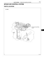
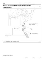
PARTS LOCATION
PZEV:
PURGE VSV
CANISTER
CANISTER PUMP MODULE
FUEL PUMP
ECM
ENGINE ROOM R/B AND
ENGINE ROOM J/B
EFI NO. 3 FUSE
EFI NO. 2 FUSE
EFI NO. 1 FUSE
(ENGINE ROOM J/B)
-
-
EFI MAIN FUSE
CIRCUIT OPENING RELAY
MASS AIR FLOW METER
EFI RELAY
INTEGRATION RELAY
A137360E01
ES–4
2AZ-FE ENGINE CONTROL SYSTEM – SFI SYSTEM
ES
EXCEPT PZEV:
PURGE VSV
CANISTER
FUEL PUMP
ECM
ENGINE ROOM R/B AND
ENGINE ROOM J/B
EFI NO. 3 FUSE
EFI NO. 2 FUSE
EFI NO. 1 FUSE
(ENGINE ROOM J/B)
-
-
EFI MAIN FUSE
CANISTER PUMP MODULE
CIRCUIT OPENING RELAY
MASS AIR FLOW METER
EFI RELAY
INTEGRATION RELAY
A137361E01
2AZ-FE ENGINE CONTROL SYSTEM – SFI SYSTEM
ES–5
ES
PZEV:
FUEL INJECTOR
IGNITION COIL
HEATED OXYGEN
SENSOR
PARK/NEUTRAL POSITION SW
INTAKE MANIFOLD
RUNNER VALVE (IMRV)
CAMSHAFT POSITION SENSOR
CAMSHAFT TIMING OIL CONTROL VALVE ASSEMBLY
CRANKSHAFT POSITION SENSOR
ENGINE COOLANT
TEMPERATURE
SENSOR
KNOCK SENSOR
THROTTLE BODY
AIR-FUEL RATIO SENSOR
A135059E01
ES–6
2AZ-FE ENGINE CONTROL SYSTEM – SFI SYSTEM
ES
EXCEPT PZEV:
FUEL INJECTOR
IGNITION COIL
AIR-FUEL RATIO SENSOR
HEATED OXYGEN
SENSOR
PARK/NEUTRAL POSITION SW
CAMSHAFT POSITION SENSOR
CAMSHAFT TIMING OIL CONTROL VALVE ASSEMBLY
CRANKSHAFT POSITION SENSOR
ENGINE COOLANT
TEMPERATURE
SENSOR
KNOCK SENSOR
THROTTLE BODY
A132270E01
2AZ-FE ENGINE CONTROL SYSTEM – SFI SYSTEM
ES–7
ES
INSTRUMENT PANEL J/B
COMBINATION METER
CLUTCH START SWITCH
IGNITION SWITCH
STOP LIGHT SW
DLC3
- IGN FUSE
- STOP FUSE
ACCELERATOR PEDAL ROD
A132271E01
ES–8
2AZ-FE ENGINE CONTROL SYSTEM – SFI SYSTEM
ES
SYSTEM DIAGRAM
M
M
EFI MAIN
EFI No. 1
EFI No. 2
EFI No. 3
Purge VSV
IGN
IG SW
ST/AM2
ALT
AM1
AM1
AM2
IG1
IG2
C/OPN
To
C/OPN
Combination
Meter
GAUGE No. 2
FL
MAIN
STOP
Stop Light SW
To IGN
To IGN
Battery
To Battery
STP
ST1-
E1
E01
E04
E03
IAC+*1
IAC-*1
W
MIL
ETCS
IMRV (Intake Manifold
Runner Valve) Motor
+BM
ALT
Generator
DLC3
TC
FC
TACH
Fuel Pump
ECM
BATT
+B
+B2
MREL
PRG
IGSW
*1: PZEV Only
EFI
To Park/Neutral Position SW
A132314E01
2AZ-FE ENGINE CONTROL SYSTEM – SFI SYSTEM
ES–9
ES
Mass Air Flow Meter
Engine Coolant Temperature Sensor
Air-fuel Ratio Sensor
Heated Oxygen Sensor
Throttle Actuator
No. 1 Fuel Injector
No. 3 Fuel Injector
No. 2 Fuel Injector
No. 4 Fuel Injector
Knock Sensor
ECM
GE01
#10
#20
#30
#40
E02
ME01
E2G
VG
THA
ETHA
THW
ETHW
To
INJ
HA1A
A1A+
A1A-
HT1B
OX1B
EX1B
KNK1
EKNK
M+
M-
A132315E01
ES–10
2AZ-FE ENGINE CONTROL SYSTEM – SFI SYSTEM
ES
Crankshaft Position Sensor
Camshaft Position Sensor
Throttle Position
Sensor
IMRV Position
Sensor
Camshaft Timing Oil Control Valve
No. 1 Ignition Coil
No. 2 Ignition Coil
No. 3 Ignition Coil
No. 4 Ignition Coil
Park/Neutral
Position SW or
Clutch Start SW
To Starter
To IG SW
To IG SW
ST
To INJ
*1: PZEV Only
*2: Automatic Transaxle Only
ECM
OC1+
OC1-
IGT1
IGT2
IGT3
IGT4
IGF1
NSW*2
STA
NE+
NE-
G2+
G2-
VCTA
VTA1
VTA2
ETA
VCIA*1
IACA*1
EIA*1
A132316E01
2AZ-FE ENGINE CONTROL SYSTEM – SFI SYSTEM
ES–11
ES
M
M
M
Combination Meter
Transponder Key ECU
Accelerator Pedal Position Sensor
FAN No. 3
FAN No. 2
FAN No. 1
A/C Condenser
Fan Motor
To Battery
To Battery
Radiator Fan Motor
Canister Pump Module
Vent Valve
Canister Pressure
Sensor
To EFI No. 3
Leak Detection Pump
PS Oil Pressure SW
ECM
SPD
FANL
IMO
IMI
VCP2
VPA2
EPA2
VCPA
VPA
EPA
FANH
VPMP
VCPP
PPMP
EPPM
MPMP
EC
EOM
CANH
CANH
CANL
CANL
PSW
IC
IC
To IG1
A132317E01
ES–12
2AZ-FE ENGINE CONTROL SYSTEM – SFI SYSTEM
ES
HOW TO PROCEED WITH
TROUBLESHOOTING
HINT:
*: Use the intelligent tester.
NEXT
NEXT
HINT:
If the display indicates a communication fault in the tester,
inspect the DLC3.
NEXT
HINT:
Record or print DTCs and freeze frame data, if necessary.
NEXT
NEXT
NEXT
NEXT
1
VEHICLE BROUGHT TO WORKSHOP
2
CUSTOMER PROBLEM ANALYSIS
3
CONNECT INTELLIGENT TESTER TO DLC3*
4
CHECK FOR DTC AND FREEZE FRAME DATA*
5
CLEAR DTC AND FREEZE FRAME DATA*
6
CONDUCT VISUAL INSPECTION
7
SET CHECK MODE DIAGNOSIS*
2AZ-FE ENGINE CONTROL SYSTEM – SFI SYSTEM
ES–13
ES
HINT:
If the engine does not start, first perform the "CHECK DTC"
procedures and "CONDUCT BASIC INSPECTION"
procedures below.
Result
B
A
NEXT
Result
B
A
NEXT
Result
B
8
CONFIRM PROBLEM SYMPTOMS
Result Proceed to
Malfunction does not occur A
Malfunction occurs B
GO TO STEP 10
9
SIMULATE SYMPTOMS
10
CHECK FOR DTC*
Result Proceed to
Trouble code A
No code B
GO TO STEP 12
11
REFER TO DTC CHART
GO TO STEP 14
12
CONDUCT BASIC INSPECTION
Result Proceed to
Malfunctioning parts not confirmed A
Malfunctioning parts confirmed B
GO TO STEP 17
ES–14
2AZ-FE ENGINE CONTROL SYSTEM – SFI SYSTEM
ES
A
Result
B
A
NEXT
Result
B
A
NEXT
NEXT
NEXT
13
REFER TO PROBLEM SYMPTOMS TABLE
Result Proceed to
Malfunctioning circuit confirmed A
Malfunctioning parts confirmed B
GO TO STEP 17
14
CHECK ECM POWER SOURCE CIRCUIT
15
CONDUCT CIRCUIT INSPECTION
Result Proceed to
Malfunction not confirmed A
Malfunction confirmed B
GO TO STEP 18
16
CHECK FOR INTERMITTENT PROBLEMS
GO TO STEP 18
17
CONDUCT PARTS INSPECTION
18
IDENTIFY PROBLEM
2AZ-FE ENGINE CONTROL SYSTEM – SFI SYSTEM
ES–15
ES
NEXT
NEXT
19
ADJUST AND/OR REPAIR
20
CONDUCT CONFIRMATION TEST
END
ES–16
2AZ-FE ENGINE CONTROL SYSTEM – SFI SYSTEM
ES
CHECK FOR INTERMITTENT
PROBLEMS
HINT:
Inspect the vehicle's ECM using check mode. Intermittent
problems are easier to detect with the intelligent tester when
the ECM is in check mode. In check mode, the ECM uses 1
trip detection logic, which is more sensitive to malfunctions
than normal mode (default), which uses 2 trip detection logic.
1. Clear the DTCs (See page ES-38).
2. Switch the ECM from normal mode to check mode using
the intelligent tester (See page ES-41).
3. Perform a simulation test.
4. Check and wiggle the harness(es), connector(s) and
terminal(s).
2AZ-FE ENGINE CONTROL SYSTEM – SFI SYSTEM
ES–17
ES
BASIC INSPECTION
When a malfunction is not confirmed by the DTC check,
troubleshooting should be carried out in all circuits
considered to be possible causes of the problem. In many
cases, by carrying out the basic engine check shown in the
following flowchart, the location of the problem can be found
quickly and efficiently. Therefore, using this check is essential
when engine troubleshooting.
NOTICE:
Conduct this check with the engine stopped and ignition
switch off.
Result
NG
OK
NG
OK
NG
OK
(a) Visually check that the air filter is not excessively
contaminated with dirt or oil.
NG
OK
NG
1
CHECK BATTERY VOLTAGE
Result Proceed to
11 V or more OK
Below 11 V NG
CHARGE OR REPLACE BATTERY
2
CHECK WHETHER ENGINE WILL CRANK
PROCEED TO PROBLEM SYMPTOMS
TABLE
3
CHECK WHETHER ENGINE STARTS
GO TO STEP 6
4
CHECK AIR FILTER
REPLACE AIR FILTER
5
CHECK IDLING SPEED
TROUBLESHOOT IDLING SPEED AND
PROCEED TO NEXT STEP
ES–18
2AZ-FE ENGINE CONTROL SYSTEM – SFI SYSTEM
ES
OK
NG
OK
NG
OK
6
CHECK FUEL PRESSURE
TROUBLESHOOT FUEL PRESSURE AND
PROCEED TO NEXT STEP
7
CHECK FOR SPARKS
TROUBLESHOOT SPARK AND PROCEED
TO NEXT STEP
PROCEED TO PROBLEM SYMPTOMS TABLE
2AZ-FE ENGINE CONTROL SYSTEM – SFI SYSTEM
ES–19
ES
REGISTRATION
NOTICE:
The Vehicle Identification Number (VIN) must be input
into the replacement ECM.
HINT:
The VIN is a 17-digit alphanumeric number. The intelligent
tester is required to register the VIN.
1. DESCRIPTION
This registration section consists of 3 parts: Input
Instructions, Read VIN and Write VIN.
(a) Input Instructions: Explains the general VIN input
instructions when using the intelligent tester.
(b) Read VIN: Explains the VIN reading process in a
flowchart. This process allows the VIN stored in the
ECM to be read in order to confirm that the two
VINs, provided with the vehicle and stored in the
vehicle's ECM, are the same.
(c) Write VIN: Explains the VIN writing process in a
flowchart. This process allows the VIN to be input
into the ECM. If the ECM is changed, or the vehicle
VIN and ECM VIN do not match, the VIN can be
registered or overwritten in the ECM by following
this procedure.
2. INPUT INSTRUCTIONS
(a) Intelligent tester
The arrow buttons (UP, DOWN, RIGHT and LEFT)
and numerical buttons (0 to 9) are used to input the
VIN.
(b) Cursor Operation
To move the cursor around the tester screen, press
the RIGHT and LEFT buttons.
(c) Alphabetical Character Input
(1) Press the UP and DOWN buttons to select the
desired alphabetical character.
(2) After selection, the cursor should move.
(d) Numeric Character Input
(1) Press the numerical button corresponding to
the number that you want to input.
(2) After input, the cursor should move.
HINT:
Numerical characters can also be selected by
using the UP and DOWN buttons.
(e) Correction
(1) When correcting the input character(s), put the
cursor onto the character using the RIGHT and
LEFT buttons.
(2) Select or input the correct character using the
UP/DOWN buttons, or the numerical buttons.
(f) Finishing Input Operation
(1) Make sure that the input VIN matches the
vehicle VIN after input.
(2) Press the ENTER button on the tester.
ES–20
2AZ-FE ENGINE CONTROL SYSTEM – SFI SYSTEM
ES
3. READ VIN
(a) Confirm the vehicle VIN.
(b) Connect the intelligent tester to the DLC3.
(c) Turn the ignition switch to the ON position.
(d) Turn the tester on.
(e) Select the following menu items: DIAGNOSIS /
ENHANCED OBD II/ VIN.
4. WRITE VIN
(a) Confirm the vehicle VIN.
(b) Connect the intelligent tester to the DLC3.
(c) Turn the ignition switch to the ON position.
(d) Turn the tester on.
Menu Screen:
Select VIN READ
DTC P0630 Set
VIN Previously Stored
VIN Not Stored
[EXIT]
[EXIT]
[EXIT]
To Menu Screen
17-digit VIN
displayed
A103812E03
2AZ-FE ENGINE CONTROL SYSTEM – SFI SYSTEM
ES–21
ES
(e) Select the following menu items: DIAGNOSIS /
ENHANCED OBD II/ VIN.
Menu Screen:
Select VIN WRITE
VIN Previously Stored
17-digit VIN displayed
To Menu Screen
To Menu
Screen
Continue to next illustration
[YES]
[YES]
[YES][NO]
[NO]
A103813E01
ES–22
2AZ-FE ENGINE CONTROL SYSTEM – SFI SYSTEM
ES
New Registration
[ENTER]
[ENTER]
[ENTER]
Continue to next illustration
Input Error
[Exit]
Input Instructions
[ENTER]
A136113E01
2AZ-FE ENGINE CONTROL SYSTEM – SFI SYSTEM
ES–23
ES
Writing Successful Writing Error Communication Error
To Menu Screen To Menu Screen To Menu Screen
[ENTER] [EXIT] [EXIT]
A103815E03
ES–24
2AZ-FE ENGINE CONTROL SYSTEM – SFI SYSTEM
ES
CHECKING MONITOR STATUS
The purpose of the monitor result (mode 06) is to allow
access to the results of on-board diagnostic monitoring tests
of specific components/systems that are not continuously
monitored. Examples are catalysts and evaporative
emissions (EVAP).
The monitor result allows the OBD II scan tool to display the
monitor status, test value, minimum test limit and maximum
test limit. These data are displayed after the vehicle has been
driven to run the monitor.
When the test value is not between the minimum test limit
and maximum test limit, the ECM (PCM) interprets this as a
malfunction. If the test value is on the borderline of the test
limits, the component is likely to malfunction in the near
future.
Perform the following instructions to view the monitor status.
Although this instruction refers to the Lexus/Toyota diagnostic
tester, it can be checked using a generic OBD II scan tool.
Refer to your scan tool operator's manual for specific
procedural information.
1. PERFORM MONITOR DRIVE PATTERN
(a) Connect the intelligent tester to the DLC3.
(b) Turn the ignition switch to the ON position and turn
the tester on.
(c) Clear the DTCs (See page ES-38).
(d) Run the vehicle in accordance with the applicable
drive pattern described in READINESS MONITOR
DRIVE PATTERN (See page ES-23). Do not turn
the ignition switch off.
NOTE:
The test results will be lost if the ignition
switch is turned off.
2. ACCESS MONITOR RESULT
(a) Select the following items from the intelligent tester
menus: DIAGNOSIS / ENHANCED OBD II /
MONITOR INFO and MONITOR RESULT. The
monitor status appears after the component name.
• INCMP: The component has not been monitored
yet.
• PASS: The component is functioning normally.
• FAIL: The component is malfunctioning.
(b) Confirm that the component is either PASS or FAIL.
(c) Select the component and press ENTER. The
accuracy test value appears if the monitor status is
either PASS or FAIL.
3. CHECK COMPONENT STATUS
(a) Compare the test value with the minimum test limit
(MIN LIMIT) and maximum test limit (MAX LIMIT).
2AZ-FE ENGINE CONTROL SYSTEM – SFI SYSTEM
ES–25
ES
(b) If the test value is between the minimum test limits
and maximum test limits, the component is
functioning normally. If not, the component is
malfunctioning. The test value is usually not near
the test limit. If the test value is on the borderline of
the test limits, the component is likely to malfunction
in the near future.
HINT:
The monitor result might be PASS on rare
occasions even if the malfunction indicator lamp
(MIL) is illuminated. This indicates the system
malfunctioned on a previous driving cycle. This
might be caused by an intermittent problem.
4. MONITOR RESULT INFORMATION
If you use a generic scan tool, multiply the test value by
the scaling value listed below.
A/F Sensor (Sensor 1):
HO2 Sensor (Sensor 2):
Catalyst:
EVAP:
Rear Oxygen Sensor Heater:
Monitor ID Test ID Scaling Unit Description
$01 $8E Multiply by 0.001 V A/F sensor deterioration level
$01 $91 Multiply by 0.004 mA A/F sensor current
Monitor ID Test ID Scaling Unit Description
$02 $07 Multiply by 0.001 V Minimum sensor voltage
$02 $08 Multiply by 0.001 V Maximum sensor voltage
$02 $8F Multiply by 0.0003 g Maximum oxygen storage capacity
Monitor ID Test ID Scaling Unit Description
$21 $A9 Multiply by 0.0003 No dimension Oxygen storage capacity of catalyst
Monitor ID Test ID Scaling Unit Description
$3D $C9 Multiply by 0.001 kPa Test value for small leak (P0456)
$3D $CA Multiply by 0.001 kPa Test value for gross leak (P0455)
$3D $CB Multiply by 0.001 kPa Test value for leak detection pump stuck OFF (P2401)
$3D $CD Multiply by 0.001 kPa Test value for leak detection pump stuck ON (P2402)
$3D $CE Multiply by 0.001 kPa Test value for vent valve stuck OFF (P2420)
$3D $CF Multiply by 0.001 kPa Test value for vent valve stuck ON (P2419)
$3D $D0 Multiply by 0.001 kPa Test value for reference orifice low flow (P043E)
$3D $D1 Multiply by 0.001 kPa Test value for reference orifice high flow (P043F)
$3D $D4 Multiply by 0.001 kPa Test value for purge VSV stuck closed (P0441)
$3D $D5 Multiply by 0.001 kPa Test value for purge VSV stuck open (P0441)
$3D $D7 Multiply by 0.001 kPa Test value for purge flow insufficient (P0441)
Monitor ID Test ID Scaling Unit Description
$42 $91 Multiply by 0.001 Ohm Oxygen sensor resistance bank 1 sensor 2