Toyota camry 2006 2011 2AZ FE fuel hệ thống nhiên liệu xe toyota camry 2AZ FE đời 2006 2011
Bạn đang xem bản rút gọn của tài liệu. Xem và tải ngay bản đầy đủ của tài liệu tại đây (3.94 MB, 43 trang )
2AZ-FE FUEL – FUEL SYSTEM
FU–1
FU
FUEL SYSTEM
PRECAUTION
1. PRECAUTION
(a) Before inspecting and repairing the fuel system,
disconnect the negative (-) battery terminal.
(b) Do not smoke or work near fire when handling the
fuel system.
(c) Keep gasoline away from rubber or leather parts.
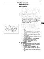
2. DISCHARGE FUEL SYSTEM PRESSURE
CAUTION:
• Perform the following procedures to prevent fuel
from spilling out before removing any fuel system
parts.
• Pressure will still remain in the fuel line even after
performing the following procedures. When
disconnecting the fuel line, cover it with a shop
rag or a piece of cloth to prevent fuel from
spraying or coming out.
(a) Disconnect the fuel pump connector.
(1) Remove the rear seat cushion assembly.
(2) Remove the rear floor service hole cover.
(3) Disconnect the fuel pump connector.
(4) Start the engine.
(5) After the engine stops, turn the ignition switch
off.
HINT:
DTC P0171/25 (fuel problem) and/or P0191/49
(fuel pressure sensor signal error) may be
detected.
(6) Crank the engine again. Check that the engine
does not start.
(7) Remove the fuel tank cap to discharge pressure
from the fuel tank.
(8) Disconnect the negative (-) battery terminal.
(9) Reconnect the fuel pump connector.
(10)Install the rear floor service hole cover.
(11)Install the rear seat.
3. FUEL SYSTEM
(a) When disconnecting the high fuel pressure line, a
large amount of gasoline will spill out, so observe
the following procedures:
(1) Discharge the fuel system pressure. (step 2)
(2) Disconnect the fuel pump tube (See page FU-
23).
(3) Drain the fuel that remains inside the fuel pump
tube.
A129607
FU–2
2AZ-FE FUEL – FUEL SYSTEM
FU
(4) To protect the disconnected fuel pump tube from
damage and contamination, cover it with a
plastic bag.
(5) Put a container under the connection part.
(b) Observe the following precautions when removing
and installing the fuel injectors:
(1) Never reuse an O-ring.
(2) When placing a new O-ring on the injector, do
not damage the O-ring.
(3) Coat a new O-ring with gasoline before installing
it.
NOTICE:
Do not use engine oil, gear oil or brake fluid.
(c) Install the injector to the delivery pipe and cylinder
head, as shown in the illustration.
NOTICE:
Before installing the injector, be sure to apply
grease or gasoline to the place where the
delivery pipe or cylinder head contacts the O-
ring of the injector.
(d) Observe the following precautions when
disconnecting the fuel delivery pipe (metallic type):
HINT:
The structure of the metallic connector is shown on
the left.
Plastic Bag
B000679E07
CORRECT
INCORRECT
O-Ring
Delivery Pipe
A131629E01
Insulator
Fuel Delivery Pipe
O-Ring
Fuel Injector
A097444E02
O-ring
Retainer
Pipe
Housing
Nylon Tube
A050709E01
2AZ-FE FUEL – FUEL SYSTEM
FU–3
FU
(1) Remove the No. 2 fuel pipe clamp.
HINT:
The No. 2 fuel pipe clamp cannot be reused.
(2) Find the metallic connector of the fuel tube
assembly.
(3) Assemble SST to the connection as shown in
the illustration.
SST 09268-21010
(4) Turn the SST, align the retainers inside the
connector with the SST chamfered parts and
insert SST into the connector.
(5) Slide the SST and the connector together
towards the fuel tube assembly.
(e) Observe the following precautions when connecting
the fuel tube connector (metallic type):
(1) Check if there is any damage or foreign objects
on the connecting part of the pipe.
(2) Match the axis of the connector with the axis of
the pipe, and push into the connector until the
connector makes a "click" sound. If the
connection is tight, apply a small amount of fresh
engine oil to the tip of the pipe.
(3) After finishing the connection, check if the pipe
and the connector are securely connected by
pulling on them.
(4) Check for fuel leaks.
Fuel Pipe
A136248E01
Retainer
(at 4 places)
SST
A130371E01
Push
B084645E01
Pull
B084645E04
FU–4
2AZ-FE FUEL – FUEL SYSTEM
FU
(5) Install a new No. 2 fuel pipe clamp.
(f) Observe the following precautions when
disconnecting the fuel tube connectors (Quick type
A):
(1) Remove the No. 1 fuel pipe clamp from the tube
connector.
(2) Check that there is no dirt or other foreign
objects on the pipe and around the connector
before disconnecting them. Clean them if
necessary.
(3) Disconnect the connector from the pipe by hand.
(4) When the connector and the pipe are stuck,
push in and pull on the connector to release it.
Pull the connector out of the pipe carefully.
(5) Check that there is no dirt or other foreign
objects on the sealing surface of the
disconnected pipe. Clean it away if necessary.
(6) Do not damage the disconnected pipe and
connector, and prevent entry of foreign objects
by covering them with a plastic bag.
Fuel Pipe
A136248E02
No. 1 Fuel
Pipe Clamp
A060083E16
Quick Type A
A088336E10
Quick Type A
Plastic Bag
B009222E04
2AZ-FE FUEL – FUEL SYSTEM
FU–5
FU
(g) Observe the following precautions when connecting
the fuel tube connectors (Quick Type A):
(1) Check if there is any damage or foreign objects
on the connecting parts of the pipes.
(2) Line up the two parts of the pipes to be
connected, and push them together until the
connector makes a "click" sound. If the pipe is
difficult to push into the connector, apply a small
amount of clean engine oil to the tip of the pipe
and reinsert it.
(3) After connecting the pipes, check that the pipe
and connector are securely connected by pulling
on them.
(4) Check for fuel leaks.
(h) Observe the following precautions when
disconnecting the fuel tube connector (Quick type
B):
(1) Before disconnecting the connector, clean off
any dirt that may be present.
(2) Pinch the tabs of the fuel tube retainer to
disengage the 2 claws. Push the retainer down
as shown in the illustration.
HINT:
Be sure to disconnect the connector by hand.
(3) If the connector and pipe are stuck, hold the fuel
pipe by hand and push and pull on the
connector. Pull the two pipes apart to separate
the connector.
(4) If there is any dirt or any other foreign objects on
the sealing surfaces of the disconnected pipes,
clean them if necessary.
(5) Do not damage the disconnected pipe and
connector, and prevent entry of foreign objects
by covering them with a plastic bag.
Quick Type A
Push
Pull
A121423E01
Quick Type B
A129459E01
Quick Type B
A091246E06
Quick Type B
Plastic Bag
A093309E03
FU–6
2AZ-FE FUEL – FUEL SYSTEM
FU
(i) Observe the following precautions when connecting
the fuel tube connector (Quick Type B):
(1) Line up the two parts of the pipes to be
connected, and fully push the fuel tube
connector and pipe together until they are fully
seated. Next, push the retainer into the
connector until its claws lock. If the pipe is
difficult to push in to the connector, apply a small
amount of clean engine oil to the tip of the pipe
and reinsert it.
(2) After connecting the pipes, check that the pipe
and connector are securely connected by pulling
on them.
(3) Check for fuel leaks.
(j) Observe the following precautions when handling a
nylon tube:
CAUTION:
• Do not twist the connection part of the nylon
tube and the quick connector when
connecting them.
• Do not bend or twist the nylon tube.
• Do not remove the EPDM protector on the
outside of the nylon tube.
• Do not close the piping by bending the nylon
tube.
4. CHECK FOR FUEL LEAKS
(a) Check that there are no fuel leaks from the fuel
system after doing any maintenance or repairs (See
page FU-9).
Quick Type B
A132390E01
2AZ-FE FUEL – FUEL SYSTEM
FU–7
FU
PARTS LOCATION
FUEL INJECTOR
FUEL PUMP
ENGINE ROOM RELAY BLOCK
ECM
A136012E01
FU–8
2AZ-FE FUEL – FUEL SYSTEM
FU
SYSTEM DIAGRAM
7
FC
44
MREL
105
#40
106
#30
107
C24
C24
C24
A24
A24
#20
108
C24
#10
12
C7 Fuel Injector (No. 1)
ECM
C9 Fuel Injector (No. 2)
C8 Fuel Injector (No. 3)
E23 Ignition Switch
C10 Fuel Injector (No. 4)
IGN
ST/AM2
INJ
EFI MAIN
65
IG2
AM2
From
Battery
From
Battery
EFI
C/OPN
54
Pump
N10 Fuel Suction Pump and Gauge Assembly
12
12
12
A136724E01
2AZ-FE FUEL – FUEL SYSTEM
FU–9
FU
ON-VEHICLE INSPECTION
1. CHECK FUEL PUMP OPERATION AND FOR FUEL
LEAKS
(a) Check fuel pump operation.
(1) Connect the intelligent tester to the DLC3.
(2) Turn the ignition switch to the ON position and
push the intelligent tester main switch on.
NOTICE:
Do not start the engine.
(3) Select the following menu items: DIAGNOSIS /
ENHANCED OBD II / ACTIVE TEST / FUEL
PUMP / SPD.
(4) Check for pressure in the fuel inlet tube from
the fuel line. Check that sound of fuel flowing in
the fuel tank can be heard. If no sound can be
heard, check the integration relay, fuel pump,
ECM and wiring connector.
(b) Check for fuel leaks.
(1) Check that there are no fuel leaks anywhere on
the system after performing maintenance. If
there is a fuel leak, repair or replace parts as
necessary.
(c) Turn the ignition switch off.
(d) Disconnect the intelligent tester from the DLC3.
2. CHECK FUEL PRESSURE
(a) Using a voltmeter, measure the battery voltage.
Standard voltage:
11 to 14 V
(b) Discharge the fuel system pressure (See page FU-
1).
(c) Disconnect the cable from the negative (-) battery
terminal.
(d) Remove the No. 1 fuel pipe clamp from the fuel tube
connector.
(e) Disconnect the fuel hose from the fuel main tube.
CAUTION:
• Always read the precautions (See page FU-1)
before disconnecting the fuel tube connector
(quick type).
• The fuel pipe line may spray fuel as a result of
retained pressure that remains in it. Do not
allow fuel to be sprayed in the engine
compartment.
No. 1 Fuel
Pipe Clamp
A060083E16
FU–10
2AZ-FE FUEL – FUEL SYSTEM
FU
(f) Install SST (pressure gauge) and the fuel tube
connector using SST as shown in the illustration.
SST 09268-31011 (09268-41500, 90467-13001,
95336-08070), 09268-45014 (09268-41200,
09268-41220, 09268-41250)
(g) Wipe up any gasoline.
(h) Reconnect the cable to the negative (-) battery
terminal.
(i) Select the following menu items: DIAGNOSIS /
ENHANCED OBD II / ACTIVE TEST / FUEL PUMP
/ SPD.
(j) Measure the fuel pressure.
Fuel pressure:
304 to 343 kPa (3.1 to 3.5 kgf/cm
2
, 44.1 to 49.7
psi)
If the pressure is high, replace the fuel pressure
regulator.
If the pressure is low, check the fuel hoses and
connections, fuel pump, fuel filter and fuel pressure
regulator.
(k) Disconnect the intelligent tester from the DLC3.
(l) Start the engine.
(m) Measure the fuel pressure at idle.
Fuel pressure:
304 to 343 kPa (3.1 to 3.5 kgf/cm
2
, 44.1 to 49.7
psi)
(n) Stop the engine.
(o) Check that the fuel pressure remains as specified
for 5 minutes after the engine has stopped.
Fuel pressure:
147 kPa (1.5 kgf/cm
2
, 21 psi) or more
If the pressure is not as specified, check the fuel
pump, pressure regulator and/or injectors.
(p) After checking the fuel pressure, disconnect the
cable from the negative battery terminal and
carefully remove the SST to prevent gasoline from
splashing.
(q) Reconnect the fuel main tube (fuel tube connector).
CAUTION:
Always read the precautions (See page FU-1)
before connecting the fuel tube connector
(quick type).
(r) Install the No. 1 fuel pipe clamp to the fuel tube
connector.
(s) Check for fuel leaks (Step 1).
SST (Pressure
Gauge)
SST (Clip)
SST (T-joint)
SST (Tube)
SST
(Hose)
SST (Tube Connector)
A105669E04
2AZ-FE FUEL – FUEL INJECTOR
FU–11
FU
ENGINE2AZ-FE FUEL
FUEL INJECTOR
COMPONENTS
FUEL INJECTOR
ASSEMBLY
NO. 2 VENTILATION
HOSE
INSULATOR
N*m (kgf*cm, ft.*lbf)
: Specified torque
Non-reusable part
O-RING
ENGINE WIRE
SPACER
7.0 (71, 62 in.*lbf)
20 (204, 15)
NO. 1 FUEL PIPE CLAMP
FUEL DELIVERY PIPE
WITH INJECTOR
NO. 1 ENGINE COVER SUB-ASSEMBLY
AIR CLEANER CAP SUB-ASSEMBLY
NO. 2 VENTILATION HOSE
PURGE VSV
VACUUM HOSE
PURGE VSV VACUUM HOSE
A136019E01
FU–12
2AZ-FE FUEL – FUEL INJECTOR
FU
REMOVAL
1. DISCHARGE FUEL SYSTEM PRESSURE
HINT:
See page FU-1.
2. DISCONNECT CABLE FROM NEGATIVE BATTERY
TERMINAL
3. REMOVE AIR CLEANER CAP SUB-ASSEMBLY (See
page ES-416)
4. REMOVE NO. 1 ENGINE COVER SUB-ASSEMBLY
(See page EM-94)
5. DISCONNECT FUEL TUBE SUB-ASSEMBLY
(a) Remove the No. 1 fuel pipe clamp.
NOTICE:
Check for foreign matter on the pipe and around
the connector before disconnecting the quick
connector. Clean the connector if necessary.
(b) If the connector and pipe are stuck, pinch the
connector, and push and pull the pipe to disconnect
them.
NOTICE:
• Do not use any tools in this procedure.
• Check for foreign matter on the sealing
surface of the disconnected pipe. Clean it if
necessary.
(c) Separate the fuel tube from the fuel hose clamp.
A136015E01
Pinch
Pinch
Pull
A136016E01
A136017E01
2AZ-FE FUEL – FUEL INJECTOR
FU–13
FU
6. DISCONNECT NO. 2 VENTILATION HOSE
(a) Disconnect the No. 2 ventilation hose from the
ventilation valve.
7. REMOVE FUEL DELIVERY PIPE WITH INJECTOR
(a) Remove the 2 wire harness clamps.
(b) Disconnect the 4 fuel injector connectors.
(c) Remove the 2 bolts, then remove the fuel delivery
pipe together with the 4 fuel injectors.
NOTICE:
Be careful not to drop the fuel injectors when
removing the fuel delivery pipe.
(d) Remove the 2 delivery pipe spacers from the
cylinder head.
(e) Remove the 4 insulators from the cylinder head.
8. REMOVE FUEL INJECTOR ASSEMBLY
(a) Pull out the 4 injectors from the delivery pipe.
(b) Remove the 4 O-rings from the injectors.
A097786
A136750
A136751
A128737
Pull Out
A097399E02
FU–14
2AZ-FE FUEL – FUEL INJECTOR
FU
INSPECTION
1. INSPECT FUEL INJECTOR ASSEMBLY
(a) Measure the resistance between the injector
terminals.
Standard resistance:
11.6 to 12.4 Ω at 20°C (68°F)
If the result is not as specified, replace the injector.
(b) Inspect the injector injection volume.
CAUTION:
Keep the injector away from sparks during this
test.
(1) Connect SST (fuel tube connector) to SST
(hose), then connect them to the fuel pipe
(vehicle side).
SST 09268-31011 (09268-41500, 90467-
13001, 95336-08070)
(2) Install the O-ring to the fuel injector.
(3) Connect SST (adapter and hose) to the
injector, and hold the injector and union with
SST (clamp).
SST 09268-31011 (09268-41110, 09268-
41300, 90467-13001)
(4) Put the injector into the graduated cylinder.
CAUTION:
Install a suitable vinyl tube onto the injector
to contain gasoline spray.
(5) Operate the fuel pump.
(6) Connect SST (wire) to the injector and the
battery for 15 seconds, and measure the
injection volume with the graduated cylinder.
Test each injector 2 or 3 times.
SST 09842-30080
Standard injection volume:
76 to 92 cm
3
(4.6 to 5.6 cu in.) per 15
seconds
Standard difference between each injector:
16 cm
3
(0.98 cu in.) or less
Ohmmeter
A116182E01
Fuel Tube
SST (Clip)
SST (Hose)
SST (Tube Connector)
A088228E08
SST
Tube
SST
A116183E02
Connect
SST
(Wire)
A075915E04
2AZ-FE FUEL – FUEL INJECTOR
FU–15
FU
(c) Inspect the fuel leakage.
(1) Disconnect the SST (wire) tester probes from
the battery and check the fuel leakage from the
injector.
Standard fuel drop:
1 drop or less per 12 minutes
(2) Turn the ignition switch off.
(3) Disconnect the cable from the negative (-)
battery terminal.
(4) Remove the SST.
(5) Disconnect the intelligent tester from the DLC3.
(6) Reconnect the fuel inlet hose (rear fuel pipe) to
the fuel main tube.
INSTALLATION
1. INSTALL FUEL INJECTOR ASSEMBLY
(a) Apply a light coat of gasoline or spindle oil to new O-
rings, then install one onto each fuel injector.
(b) Apply a light coat of gasoline or spindle oil to the
part of the fuel delivery pipe which comes into
contact with the O-ring of the fuel injector.
(c) Apply a light coat of gasoline or spindle oil to the O-
ring again, then install the right and left fuel injectors
onto the fuel delivery pipe.
NOTICE:
Make sure that the O-ring is not cracked or
jammed before installing the injector.
(d) Check that the fuel injector rotates smoothly. If the
fuel injector does not rotate, replace the O-ring.
2. INSTALL FUEL DELIVERY PIPE WITH INJECTOR
(a) Install 4 new insulators into the cylinder head.
(b) Install the 2 delivery pipe spacers onto the cylinder
head.
A116184
New O-Ring
A097400E02
CORRECT
INCORRECT
O-Ring
Delivery Pipe
A131629E01
A128737
FU–16
2AZ-FE FUEL – FUEL INJECTOR
FU
(c) Install the fuel delivery pipe together with the 4 fuel
injectors, then temporarily tighten the 2 bolts.
NOTICE:
Be careful not to drop the fuel injectors when
installing the fuel delivery pipe.
(d) Check that the fuel injector rotates smoothly.
If the fuel injector does not rotate smoothly, replace
the O-ring.
(e) Tighten the 2 bolts to the specified torque.
Torque: 20 N*m (204 kgf*cm, 15 ft.*lbf)
(f) Connect the 4 fuel injector connectors.
(g) Install the 2 wire harness clamps.
3. INSTALL NO. 2 VENTILATION HOSE
(a) Connect the ventilation hose to the ventilation valve.
NOTICE:
Make sure that the paint mark and hose clamp
are positioned as shown in the illustration after
connecting the hose.
4. CONNECT FUEL TUBE SUB-ASSEMBLY
(a) Install the fuel tube to the fuel hose clamp.
Insulator
Fuel Delivery Pipe
O-Ring
Fuel Injector
A097444E02
A136751
A136750
White Paint Mark
“A”
UP
LH
View: “A”
A095428E03
A136017E01
2AZ-FE FUEL – FUEL INJECTOR
FU–17
FU
(b) Push the fuel tube connector until it makes a "click"
sound.
(c) Install the No. 1 fuel pipe clamp.
5. INSTALL AIR CLEANER CAP SUB-ASSEMBLY (See
page ES-419)
6. CONNECT CABLE TO NEGATIVE BATTERY
TERMINAL
7. CHECK FOR FUEL LEAKS
HINT:
See page FU-9.
8. INSTALL NO. 1 ENGINE COVER SUB-ASSEMBLY
(See page EM-121)
Push
A103968E03
A136015E01
FU–18
2AZ-FE FUEL – FUEL PRESSURE PULSATION DAMPER
FU
ENGINE2AZ-FE FUEL
FUEL PRESSURE PULSATION DAMPER
COMPONENTS
AIR CLEANER CAP SUB-ASSEMBLY
FUEL PRESSURE PULSATION DAMPER ASSEMBLY
NO. 1 ENGINE COVER SUB-ASSEMBLY
NO. 2 FUEL PIPE CLAMP
9.0 (92, 80 in.*lbf)
9.0 (92, 80 in.*lbf)
N*m (kgf*cm, ft.*lbf)
: Specified torque
Non-reusable part
NO. 2 VENTILATION HOSE
PURGE VSV
VACUUM HOSE
PURGE VSV VACUUM HOSE
AIR CLEANER
FILTER ELEMENT
FUEL TUBE SUB-ASSEMBLY
A141106E01
2AZ-FE FUEL – FUEL PRESSURE PULSATION DAMPER
FU–19
FU
REMOVAL
1. DISCHARGE FUEL SYSTEM PRESSURE
HINT:
See page FU-1.
2. DISCONNECT CABLE FROM NEGATIVE BATTERY
TERMINAL
3. REMOVE NO. 1 ENGINE COVER SUB-ASSEMBLY
(See page EM-94)
4. REMOVE AIR CLEANER CAP SUB-ASSEMBLY (See
page ES-416)
5. DISCONNECT FUEL TUBE SUB-ASSEMBLY
HINT:
Disconnect the metallic type connector (See page FU-1).
6. REMOVE FUEL PRESSURE PULSATION DAMPER
ASSEMBLY
(a) Remove the 2 bolts and fuel pressure pulsation
damper.
INSTALLATION
1. INSTALL FUEL PRESSURE PULSATION DAMPER
ASSEMBLY
(a) Apply a light coat of gasoline or spindle oil to the O-
ring of the fuel pressure pulsation damper.
(b) Install the fuel pressure pulsation damper with the 2
bolts.
Torque: 9.0 N*m (90 kgf*cm, 80 in.*lbf)
NOTICE:
Make sure that the O-ring is not cracked or
jammed before installing the damper.
2. INSTALL FUEL TUBE SUB-ASSEMBLY
HINT:
Connect the metallic type connector (See page FU-1).
3. INSTALL AIR CLEANER CAP SUB-ASSEMBLY (See
page ES-419)
4. CONNECT CABLE TO NEGATIVE BATTERY
TERMINAL
A125338
O-Ring
A125339E01
A125338
FU–20
2AZ-FE FUEL – FUEL PRESSURE PULSATION DAMPER
FU
5. CHECK FOR FUEL LEAKS
HINT:
See page FU-9.
6. INSTALL NO. 1 ENGINE COVER SUB-ASSEMBLY
(See page EM-121)
2AZ-FE FUEL – FUEL PUMP
FU–21
FU
ENGINE2AZ-FE FUEL
FUEL PUMP
COMPONENTS
GASKET
N*m (kgf*cm, ft.*lbf)
: Specified torque
Non-reusable part
CLIP
FUEL SUCTION TUBE ASSEMBLY
WITH PUMP AND GAUGE
FUEL TANK VENT TUBE SET PLATE
REAR FLOOR SERVICE HOLE COVER
REAR SEAT CUSHION ASSEMBLY
x8
5.9 (60, 52 in.*lbf)
FUEL PUMP TUBE SUB-ASSEMBLY
A136244E01
FU–22
2AZ-FE FUEL – FUEL PUMP
FU
FUEL SENDER GAUGE ASSEMBLY
FUEL NO. 1 SUCTION SUPPORT
FUEL PUMP
O-RING
O-RING
FUEL NO. 1 TANK BAND BRACKET
FUEL PRESSURE REGULATOR ASSEMBLY
FUEL PUMP HARNESS
Non-reusable part
E-RING
SPRING
FUEL SUCTION PLATE SUB-ASSEMBLY
A136245E01
2AZ-FE FUEL – FUEL PUMP
FU–23
FU
REMOVAL
1. DISCHARGE FUEL SYSTEM PRESSURE
HINT:
See page FU-1.
2. DISCONNECT CABLE FROM NEGATIVE BATTERY
TERMINAL
3. REMOVE REAR SEAT CUSHION ASSEMBLY (for
Fixed Seat Type) (See page SE-77)
4. REMOVE REAR SEAT CUSHION ASSEMBLY (for
Fold Down Seat Type) (See page SE-47)
5. REMOVE REAR SEAT CUSHION ASSEMBLY (for
Reclining Seat Type) (See page SE-62)
6. REMOVE REAR FLOOR SERVICE HOLE COVER
(a) Remove the rear floor service hole cover.
(b) Disconnect the fuel pump connector.
7. SEPARATE FUEL PUMP TUBE SUB-ASSEMBLY
(a) Remove the tube joint clip, and pull out the fuel
pump tube.
NOTICE:
• Check that there is no dirt around the fuel
tube joint before this work and clean any dirt
away.
• It is necessary to prevent mud or dirt from
entering the fuel tube joint. If mud enters the
joint, the O-rings may not seal the fuel tube
connector and fuel suction plate properly.
• Do not use any tools in this work.
• Do not bend or twist the nylon tube.
• After disconnecting, cover the fuel tube joint
with a plastic bag.
• If the fuel tube joint and fuel suction plate are
stuck, pinch the fuel tank tube between
fingers, and turn it carefully to release.
Disconnect the fuel tank tube.
A129478
Tube Joint Clip
Nylon Tube
Fuel Tube Joint
O-Ring
Tube Joint Clip
A129479E02
FU–24
2AZ-FE FUEL – FUEL PUMP
FU
8. REMOVE FUEL TANK VENT TUBE SET PLATE
(a) Remove the 8 bolts and set plate.
9. REMOVE FUEL SUCTION TUBE ASSEMBLY WITH
PUMP AND GAUGE
(a) Pull out the fuel suction tube from the fuel tank.
NOTICE:
• Do not damage the fuel pump filter.
• Be careful that the arm of the sender gauge
does not bend.
(b) Remove the gasket from the fuel suction tube.
DISASSEMBLY
1. REMOVE FUEL SENDER GAUGE ASSEMBLY
(a) Disconnect the fuel sender gauge connector.
A129480
A139190
Gasket
A136023E01
A136021
2AZ-FE FUEL – FUEL PUMP
FU–25
FU
(b) Unlock the fuel sender gauge, and slide it to
remove.
2. REMOVE FUEL NO. 1 TANK BAND BRACKET
(a) Using needle nozzle pliers, remove the E-ring.
(b) Disengage the 4 claws of the fuel No. 1 suction
support and remove the fuel No. 1 tank band
bracket from the fuel suction plate with the fuel filter.
(c) Remove the spring from the fuel suction plate.
3. REMOVE FUEL NO. 1 SUCTION SUPPORT
(a) Using a screwdriver with the tip taped, disengage
the claw and remove the fuel No. 1 suction support.
A136022
E-Ring
A136234E01
A136232
A136233