Hệ thống điều khiển động cơ 2GR-FE trên xe Toyota Camry đời 2006 - 2011
Bạn đang xem bản rút gọn của tài liệu. Xem và tải ngay bản đầy đủ của tài liệu tại đây (13.75 MB, 534 trang )
2GR-FE ENGINE CONTROL SYSTEM – SFI SYSTEM
ES–1
ES
SFI SYSTEM
PRECAUTION
NOTICE:
• Perform the RESET MEMORY (AT) initialization
operation after replacing the automatic transmission
assembly, engine assembly or ECM (See page AX-25).
• Perform REGISTRATION (VIN registration) when
replacing the ECM (See page ES-20).
ES–2
2GR-FE ENGINE CONTROL SYSTEM – SFI SYSTEM
ES
DEFINITION OF TERMS
Terms Definition
Monitor Description Description of what ECM monitors and how to detect malfunctions (monitoring purpose and
its details).
Related DTCs A group of diagnostic trouble codes that are output by ECM based on the same
malfunction detection logic.
Typical Enabling Condition Preconditions that allow ECM to detect malfunctions.
With all preconditions satisfied, ECM sets DTC when monitored value(s) exceeds
malfunction threshold(s).
Sequence of Operation Order of monitor priority, applied if multiple sensors and components are involved in single
malfunction detection process.
Each sensor and component monitored in turn and not monitored until previous detection
operation is completed.
Required Sensor/Components Sensors and components used by ECM to detect each malfunction.
Frequency of Operation Number of times ECM checks for each malfunction during each driving cycle.
"Once per driving cycle" means that ECM checks for malfunctions only once in single
driving cycle.
"Continuous" means that ECM checks for malfunctions whenever enabling conditions are
met.
Duration Minimum time for which ECM must detect continuous deviation in monitored value(s) in
order to set DTC. Timing begins when Typical Enabling Conditions are met.
Malfunction Thresholds Value, beyond which, ECM determines malfunctions exist and sets DTCs.
MIL Operation Timing of MIL illumination after a malfunction is detected.
"Immediate" means that ECM illuminates MIL as soon as a malfunction is detected.
"2 driving cycle" means that ECM illuminates MIL if the same malfunction is detected twice
during next sequential driving cycle.
2GR-FE ENGINE CONTROL SYSTEM – SFI SYSTEM
ES–3
ES
PARTS LOCATION
ECM
ENGINE ROOM R/B
- EFI RELAY
- A/F RELAY
- C/OPN RELAY
- ST CUT RELAY
- ST RELAY
PURGE VSV
ACTIVE MOUNT CONTROL VSV
(BANK 1 SENSOR 2)
(BANK 2 SENSOR 2)
- IG2 RELAY
HEATED OXYGEN SENSOR
HEATED OXYGEN SENSOR
FUEL PUMP
CANISTER
MASS AIR FLOW METER
A134870E01
ES–4
2GR-FE ENGINE CONTROL SYSTEM – SFI SYSTEM
ES
ACCELERATOR PEDAL
COMBINATION METER
INSTRUMENT PANEL J/B
- IGN FUSE
- STOP FUSE
DLC3
STOP LIGHT SWITCH
A139510E01
2GR-FE ENGINE CONTROL SYSTEM – SFI SYSTEM
ES–5
ES
IGNITION COIL WITH IGNITER
VVT SENSOR FOR EXHAUST CAMSHAFT
(BANK 2)
VVT SENSOR FOR EXHAUST CAMSHAFT (BANK 1)
VVT SENSOR FOR INTAKE CAMSHAFT
(BANK 2)
VVT SENSOR (BANK 1 INTAKE SIDE)
(BANK 2 INTAKE SIDE)
CRANKSHAFT POSITION SENSOR
ENGINE COOLANT
TEMPERATURE SENSOR
(BANK 2 EXHAUST SIDE)
(BANK 1 INTAKE SIDE)
CAMSHAFT TIMING OIL CONTROL VALVE ASSEMBLY
FUEL INJECTOR
AIR FUEL RATIO SENSOR
(BANK 2 SENSOR 1)
AIR FUEL RATIO SENSOR (BANK 1 SENSOR 1)
CAMSHAFT TIMING OIL CONTROL VALVE ASSEMBLY
CAMSHAFT TIMING OIL CONTROL VALVE ASSEMBLY
CAMSHAFT TIMING OIL CONTROL VALVE ASSEMBLY
A114586E05
ES–6
2GR-FE ENGINE CONTROL SYSTEM – SFI SYSTEM
ES
KNOCK SENSOR
KNOCK SENSOR
THROTTLE BODY
(BANK 1)
(BANK 2)
(THROTTLE POSITION
SENSOR)
ACIS ACTUATOR
A114543E04
2GR-FE ENGINE CONTROL SYSTEM – SFI SYSTEM
ES–7
ES
SYSTEM DIAGRAM
1. Without Smart Key System:
IG2
IG2
IGN
GAUGE No. 2
IG SW
ST/AM2
AM2
AM1
AM1
ST
ALT
IG2
NSW
STA
+BM
BATT
MREL
MIL
A
W
SPD
OC1+
OC1-
OE1+
OE1-
OE2+
OE2-
OC2+
OC2-
ECM
IGSW
FC
IG1
ST2
ST1
PNP SW
Combination Meter
VVT OCV (Intake Side RH)
VVT OCV (Intake Side LH)
VVT OCV (Exhaust Side RH)
VVT OCV (Exhaust Side LH)
Fuel Pump
C/OPN
ETCS
EFI No. 1
EFI MAIN
EFI
Battery
Starter
FL MAIN
E02
E05
E1
A137635E02
ES–8
2GR-FE ENGINE CONTROL SYSTEM – SFI SYSTEM
ES
APP Sensor
Transmission
Control ECU
Stop Light SW
STOP
IGN
ECM
VCP2
VPA2
VPA
EPA
IMO
STP
PSW
ST1-
IMI
E04
E01
E03
ME01
CAN+
CAN-
EPA2
VCPA
+B
VG
+B2
AICV
ACIS
PRG
ACM
THA
E2G
ETHA
HT1B
EX1B
OX1B
HT2B
EX2B
OX2B
A
B
EFI No. 3
EFI No. 2
VSV for ACIS
VSV for ACIS
MAF Meter
VSV for EVAP System
VSV for Active Control Mount System
HO2 Sensor
(Bank 1 Sensor 2)
HO2 Sensor
(Bank 2 Sensor 2)
Power Steering Oil Pressure SW
Transponder Key
ECU
A137631E02
2GR-FE ENGINE CONTROL SYSTEM – SFI SYSTEM
ES–9
ES
Knock Sensor (Bank 1)
Knock Sensor (Bank 2)
No. 1 Fuel Injector
No. 2 Fuel Injector
No. 3 Fuel Injector
No. 4 Fuel Injector
No. 5 Fuel Injector
No. 6 Fuel Injector
To IG2 Relay
ECM
KNK1
MPMP
EPPM
KNK2
EKN2
VV1+
VCV1
VV1-
VV2+
VCV2
VV2-
EV1+
VCE1
EV1-
EV2+
VCE2
CANH
CANL
EV2-
EKNK
#10
#20
#30
#40
#50
#60
Canister Pump Module
B
PPMP
VCPP
VPMP
To Main Body ECU
VVT Sensor
(Bank 1 Intake Side)
VVT Sensor
(Bank 2 Intake Side)
VVT Sensor
(Bank 1 Exhaust Side)
VVT Sensor
(Bank 2 Exhaust Side)
A137632E02
ES–10
2GR-FE ENGINE CONTROL SYSTEM – SFI SYSTEM
ES
Crankshaft Position Sensor
DLC3
Ignition Coil (No. 1)
Ignition Coil (No. 2)
Ignition Coil (No. 3)
Ignition Coil (No. 4)
Ignition Coil (No. 5)
Ignition Coil (No. 6)
To IG2 Relay
ECM
NE+
IGT1
IGT2
IGT3
IGT4
IGT5
IGT6
IGF1
NE-
TC
VTA1
VTA2
GE01
HA1A
HA2A
A1A+
A1A-
A2A+
A2A-
ETA
THW
M+
M-
VCTA
ETHW
Throttle Body
Assembly
ECT Sensor
(Bank 1 Sensor 1)
A/F Sensor
(Bank 2 Sensor 1)
A/F Sensor
A/F
A/F
To Battery
To EFI Relay
Noise Filter (RH Side)
Noise Filter (LH Side)
A137633E02
2GR-FE ENGINE CONTROL SYSTEM – SFI SYSTEM
ES–11
ES
GAUGE No. 1
Park / Neutral Position SW
Transmission Control
ECU
ECM
S
P
R
N
D
SFTD
SFTU
CCS
Transmission Control SW
ECU IG No. 2
Spiral Cable
Cruise Control SW
To IG1 Relay
To IG1 Relay
A137634E02
ES–12
2GR-FE ENGINE CONTROL SYSTEM – SFI SYSTEM
ES
2. With Smart Key System:
GAUGE No. 2
Combinatiion Meter
MIL
VVT OCV (Intake Side RH)
VVT OCV (Intake Side LH)
VVT OCV (Exhaust Side RH)
VVT OCV (Exhaust Side LH)
W
SPD
OC1+
OC1-
OE1+
OE1-
OE2+
OE2-
OC2+
OC2-
E02
E05
E1
ECM
STSW
STAR
IGSW
BATT
MREL
+BM
FC
NSW
STA
ACCR
To ECU-ACC Fuse
Main Body ECU
ACC
STR
STSW
STR2
ACCR
IG2D
IG2
IGN
To IG2 Fuse
ST CUT
ETCS
PNP SW
ST/AM2
ST
To IGN Fuse
Fuel Pump
C/OPN
EFI No. 1
EFI MAIN
EFI
Battery
FL MAIN
Starter
A
A137630E02
2GR-FE ENGINE CONTROL SYSTEM – SFI SYSTEM
ES–13
ES
APP Sensor
Transmission
Control ECU
Stop Light SW
STOP
IGN
ECM
VCP2
VPA2
VPA
EPA
IMO
STP
PSW
ST1-
IMI
E04
E01
E03
ME01
CAN+
CAN-
EPA2
VCPA
+B
VG
+B2
AICV
ACIS
PRG
ACM
THA
E2G
ETHA
HT1B
EX1B
OX1B
HT2B
EX2B
OX2B
A
B
EFI No. 3
EFI No. 2
VSV for ACIS
VSV for ACIS
MAF Meter
VSV for EVAP System
VSV for Active Control Mount System
HO2 Sensor
(Bank 1 Sensor 2)
HO2 Sensor
(Bank 2 Sensor 2)
Power Steering Oil Pressure SW
Transponder Key
ECU
A137631E02
ES–14
2GR-FE ENGINE CONTROL SYSTEM – SFI SYSTEM
ES
Knock Sensor (Bank 1)
Knock Sensor (Bank 2)
No. 1 Fuel Injector
No. 2 Fuel Injector
No. 3 Fuel Injector
No. 4 Fuel Injector
No. 5 Fuel Injector
No. 6 Fuel Injector
To IG2 Relay
ECM
KNK1
MPMP
EPPM
KNK2
EKN2
VV1+
VCV1
VV1-
VV2+
VCV2
VV2-
EV1+
VCE1
EV1-
EV2+
VCE2
CANH
CANL
EV2-
EKNK
#10
#20
#30
#40
#50
#60
Canister Pump Module
B
PPMP
VCPP
VPMP
To Main Body ECU
VVT Sensor
(Bank 1 Intake Side)
VVT Sensor
(Bank 2 Intake Side)
VVT Sensor
(Bank 1 Exhaust Side)
VVT Sensor
(Bank 2 Exhaust Side)
A137632E02
2GR-FE ENGINE CONTROL SYSTEM – SFI SYSTEM
ES–15
ES
Crankshaft Position Sensor
DLC3
Ignition Coil (No. 1)
Ignition Coil (No. 2)
Ignition Coil (No. 3)
Ignition Coil (No. 4)
Ignition Coil (No. 5)
Ignition Coil (No. 6)
To IG2 Relay
ECM
NE+
IGT1
IGT2
IGT3
IGT4
IGT5
IGT6
IGF1
NE-
TC
VTA1
VTA2
GE01
HA1A
HA2A
A1A+
A1A-
A2A+
A2A-
ETA
THW
M+
M-
VCTA
ETHW
Throttle Body
Assembly
ECT Sensor
(Bank 1 Sensor 1)
A/F Sensor
(Bank 2 Sensor 1)
A/F Sensor
A/F
A/F
To Battery
To EFI Relay
Noise Filter (RH Side)
Noise Filter (LH Side)
A137633E02
ES–16
2GR-FE ENGINE CONTROL SYSTEM – SFI SYSTEM
ES
GAUGE No. 1
Park / Neutral Position SW
Transmission Control
ECU
ECM
S
P
R
N
D
SFTD
SFTU
CCS
Transmission Control SW
ECU IG No. 2
Spiral Cable
Cruise Control SW
To IG1 Relay
To IG1 Relay
A137634E02
2GR-FE ENGINE CONTROL SYSTEM – SFI SYSTEM
ES–17
ES
HOW TO PROCEED WITH
TROUBLESHOOTING
HINT:
*: Use the intelligent tester.
NEXT
NEXT
HINT:
If the display indicates a communication fault in the tester,
inspect the DLC3.
NEXT
HINT:
Record or print DTCs and freeze frame data, if necessary.
NEXT
NEXT
NEXT
NEXT
HINT:
If the engine does not start, perform steps 10 and 12 first.
1
VEHICLE BROUGHT TO WORKSHOP
2
CUSTOMER PROBLEM ANALYSIS
3
CONNECT INTELLIGENT TESTER TO DLC3*
4
CHECK DTC AND FREEZE FRAME DATA*
5
CLEAR DTC AND FREEZE FRAME DATA*
6
CONDUCT VISUAL INSPECTION
7
SET CHECK MODE DIAGNOSIS*
8
CONFIRM PROBLEM SYMPTOMS
ES–18
2GR-FE ENGINE CONTROL SYSTEM – SFI SYSTEM
ES
Result
B
A
NEXT
Result
B
A
NEXT
Result
B
A
Result
Result Proceed to
Malfunction does not occur A
Malfunction occurs B
GO TO STEP 10
9
SIMULATE SYMPTOMS
10
CHECK FOR DTCS*
Result Proceed to
Trouble code A
No code B
GO TO STEP 12
11
REFER TO DTC CHART
GO TO STEP 14
12
CONDUCT BASIC INSPECTION
Result Proceed to
Malfunctioning parts not confirmed A
Malfunctioning parts confirmed B
GO TO STEP 17
13
REFER TO PROBLEM SYMPTOMS TABLE
Result Proceed to
Malfunctioning circuit confirmed A
2GR-FE ENGINE CONTROL SYSTEM – SFI SYSTEM
ES–19
ES
B
A
NEXT
Result
B
A
NEXT
NEXT
NEXT
NEXT
Malfunctioning parts confirmed B
GO TO STEP 17
Result Proceed to
14
CHECK ECM POWER SOURCE CIRCUIT
15
CONDUCT CIRCUIT INSPECTION
Result Proceed to
Malfunction not confirmed A
Malfunction confirmed B
GO TO STEP 18
16
CHECK FOR INTERMITTENT PROBLEMS
GO TO STEP 18
17
CONDUCT PARTS INSPECTION
18
IDENTIFY PROBLEM
19
ADJUST AND/OR REPAIR
ES–20
2GR-FE ENGINE CONTROL SYSTEM – SFI SYSTEM
ES
NEXT
20
CONDUCT CONFIRMATION TEST
END
2GR-FE ENGINE CONTROL SYSTEM – SFI SYSTEM
ES–21
ES
CHECK FOR INTERMITTENT
PROBLEMS
HINT:
Inspect the vehicle's ECM using check mode. Intermittent
problems are easier to detect with an intelligent tester when
the ECM is in check mode. In check mode, the ECM uses 1
trip detection logic, which is more sensitive to malfunctions
than normal mode (default), which uses 2 trip detection logic.
1. Clear the DTCs.
2. Switch the ECM from normal mode to check mode using
an intelligent tester (See page ES-49).
3. Perform a simulation test (See page IN-40).
4. Check and wiggle the harness(es), connector(s) and
terminal(s) (See page IN-45).
ES–22
2GR-FE ENGINE CONTROL SYSTEM – SFI SYSTEM
ES
BASIC INSPECTION
When the malfunction is not confirmed by the DTC check,
troubleshooting should be carried out in all circuits
considered to be possible causes of the problem. In many
cases, by carrying out the basic engine check shown in the
following flowchart, the location of the problem can be found
quickly and efficiently. Therefore, using this check is essential
when troubleshooting the engine.
NOTICE:
Carry out this check with the engine stopped and the
engine switch off.
Result
NG
OK
NG
OK
NG
OK
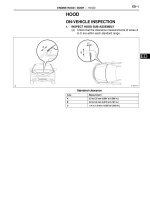
(a) Visually check that the air filter is not excessively
contaminated with dirt or oil.
NG
OK
NG
1
CHECK BATTERY VOLTAGE
Result Proceed to
11 V or more OK
Below 11 V NG
CHARGE OR REPLACE BATTERY
2
CHECK WHETHER ENGINE CRANKS
PROCEED TO PROBLEM SYMPTOMS
TABLE
3
CHECK WHETHER ENGINE STARTS
GO TO STEP 6
4
CHECK AIR FILTER
REPLACE AIR FILTER
5
CHECK IDLING SPEED
TROUBLESHOOT IDLING SPEED AND
PROCEED TO NEXT STEP
2GR-FE ENGINE CONTROL SYSTEM – SFI SYSTEM
ES–23
ES
OK
NG
OK
NG
OK
6
CHECK FUEL PRESSURE
TROUBLESHOOT FUEL PRESSURE AND
PROCEED TO NEXT STEP
7
CHECK FOR SPARKS
TROUBLESHOOT SPARK AND PROCEED
TO NEXT STEP
PROCEED TO PROBLEM SYMPTOMS TABLE
ES–24
2GR-FE ENGINE CONTROL SYSTEM – SFI SYSTEM
ES
REGISTRATION
NOTICE:
The Vehicle Identification Number (VIN) must be input
into the replacement ECM.
HINT:
The VIN is in the form of a 17-digit alphanumeric vehicle
identification number. An intelligent tester is required to
register the VIN.
1. INPUT INSTRUCTIONS
(a) The general VIN input instructions using an
intelligent tester are explained below:
(b) The arrow buttons (UP, DOWN, RIGHT and LEFT)
and numerical buttons (0 to 9) are used, in order to
input the VIN.
(c) Cursor Operation
To move the cursor around the tester screen, press
the RIGHT and LEFT buttons.
(d) Alphabetical Character Input
(1) Press the UP and DOWN buttons to select the
desired alphabetical character.
(e) Numeric Character Input
(1) Press the numerical button corresponding to
the number that you want to input.
HINT:
Numerical characters can be selected by using
the UP and DOWN buttons.
(f) Correction
(1) When correcting the input character(s), put the
cursor onto the character using the RIGHT or
LEFT button.
(2) Select or input the correct character using the
UP and DOWN buttons, or the numerical
buttons.
(g) Finishing Input Operation
(1) Make sure that the input VIN matches the
vehicle VIN after input.
(2) Press the ENTER button on the tester.
2. READ VIN (Vehicle Identification Number)
(a) The flowchart of the VIN reading process is shown.
This process allows the VIN stored in the ECM to be
read, in order to confirm that the two VINs, provided
with the vehicle and stored in the vehicle's ECM, are
the same.
(b) Read VIN using an intelligent tester.
(c) Check the vehicle's VIN.
(d) Connect the intelligent tester to the DLC3.
(e) Turn the ignition switch on (IG).
(f) Turn the tester on.
2GR-FE ENGINE CONTROL SYSTEM – SFI SYSTEM
ES–25
ES
(g) Enter the following menus: DIAGNOSIS /
ENHANCED OBD ll / VIN.
3. WRITE VIN
(a) The flowchart of the VIN writing process is shown.
This process allows the VIN to be input into the
ECM. If the ECM is changed, or the VINs do not
match, the VIN can be registered, or overwritten in
the ECM by following this procedure.
(b) Write VIN using the intelligent tester.
(c) Check the vehicle's VIN.
(d) Connect the intelligent tester to the DLC3.
(e) Turn the ignition switch on (IG).
(f) Turn the tester on.
Menu Screen:
Select VIN READ
DTC P0630 Set
VIN Previously Stored
VIN Not Stored
[EXIT]
[EXIT]
[EXIT]
To Menu Screen
17-digit VIN
displayed
A103812E03