Toyota camry 2006 2011 brake 1 hệ thống thắng trên toyota camry đời 2006 2011
Bạn đang xem bản rút gọn của tài liệu. Xem và tải ngay bản đầy đủ của tài liệu tại đây (23.46 MB, 618 trang )
BRAKE CONTROL – ANTI-LOCK BRAKE SYSTEM
BC–1
BC
ANTI-LOCK BRAKE SYSTEM
PRECAUTION
1. EXPRESSIONS OF IGNITION SWITCH
The type of ignition switch used on this model differs
according to the specifications of the vehicle.
The expressions listed in the table below are used in this
section.
2. TROUBLESHOOTING PRECAUTION
HINT:
The anti-lock brake system includes the ABS and EBD.
(a) When there is a malfunction in the terminal contact
points or installation problems with parts, removing
and installing the suspected problem parts may
return the system to normal, either completely or
temporarily.
(b) In order to determine the malfunctioning area, be
sure to check the conditions at the time the
malfunction occurred, such as by the DTC output
and the freeze frame data output, and record it
before disconnecting each connector or removing
and installing parts.
(c) Be sure to remove and install the brake actuator
and each individual sensor with the ignition switch
off unless otherwise specified in the inspection
procedure.
(d) If the brake actuator or a sensor has been removed
and installed, it is necessary to check the system for
problems after the parts have been reassembled.
Check for DTCs using the intelligent tester, also
check that system functions and signals received by
the ECU are normal using test mode.
3. CAN COMMUNICATION SYSTEM PRECAUTION
(a) The CAN communication system is used for data
communication between each of the ECUs and
sensors. If there is trouble in the CAN
communication line, a DTC of the communication
line is output.
(b) If a DTC of the CAN communication line is output,
repair the malfunction in the communication line and
troubleshoot the anti-lock brake system.
Expression
Switch Type
Ignition Switch (Position) Engine Switch (Condition)
Ignition switch off LOCK off
Ignition switch on (IG) ON on (IG)
Ignition switch on (ACC) ACC on (ACC)
Engine start START start
BC–2
BRAKE CONTROL – ANTI-LOCK BRAKE SYSTEM
BC
(c) In order to enable CAN communication, a specific
type of wiring is used for the CAN communication
lines. The wiring used for each communication line
is a twisted pair of wires that have an equal length.
A bypass wire should not be used, because the data
being transmitted will be corrupted.
BRAKE CONTROL – ANTI-LOCK BRAKE SYSTEM
BC–3
BC
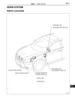
PARTS LOCATION
- SKID CONTROL ECU
FRONT SPEED SENSOR ROTOR
FRONT SPEED SENSOR ROTOR
ECM
ECM
(2GR-FE)
(2AZ-FE)
BRAKE MASTER CYLINDER ASSEMBLY
- BRAKE FLUID LEVEL WARNING SWITCH
(REAR SPEED SENSOR)
(REAR SPEED SENSOR)
REAR SPEED SENSOR
ROTOR
REAR SPEED SENSOR ROTOR
BRAKE ACTUATOR
FRONT SPEED SENSOR
SKID CONTROL SENSOR
FRONT SPEED SENSOR
SKID CONTROL SENSOR
ENGINE ROOM R/B
- FUSIBLE LINK (ABS NO. 1)
- FUSIBLE LINK (ABS NO. 2)
C131985E01
BC–4
BRAKE CONTROL – ANTI-LOCK BRAKE SYSTEM
BC
COMBINATION METER ASSEMBLY
- ABS WARNING LIGHT
- BRAKE WARNING LIGHT
PARKING BRAKE
SWITCH
INSTRUMENT PANEL J/B
- ECU IG NO. 2 FUSE
PARKING BRAKE SWITCH
(MANUAL TRANSAXLE)
DLC3
(AUTOMATIC
TRANSAXLE)
STOP LIGHT SWITCH
C131984E01
BRAKE CONTROL – ANTI-LOCK BRAKE SYSTEM
BC–5
BC
SYSTEM DIAGRAM
Transmitting ECU Receiving ECU Signals Communication method
Skid control ECU Combination meter
• ABS warning light signal
• BRAKE warning light signal
CAN communication system
Brake Actuator Assembly (Skid Control ECU with Actuator)
Motor Relay Motor
SolenoidSolenoid Relay
ECM
Combination Meter Assembly
ABS Warning Light
BRAKE Warning Light
Speedometer
Skid Control
ECU
Parking Brake
Switch
Stop Light Switch
Speed Sensor
(On Each Wheel)
CAN Communication System
Main Body ECU
C131987E01
BC–6
BRAKE CONTROL – ANTI-LOCK BRAKE SYSTEM
BC
ECM Skid control ECU Shift position signal CAN communication system
Transmitting ECU Receiving ECU Signals Communication method
BRAKE CONTROL – ANTI-LOCK BRAKE SYSTEM
BC–7
BC
SYSTEM DESCRIPTION
1. SYSTEM DESCRIPTION
HINT:
The skid control ECU is located within the brake actuator
assembly.
(a) ABS
(Anti-lock Brake System)
The ABS helps prevent the wheels from locking
when the brakes are applied firmly or when braking
on a slippery surface.
Hydraulic Pressure
CAN Communication System
Combination Meter Assembly
ABS Warning
Light
Each Wheel
Cylinder
Solenoid Valves
Pump Motor
Skid Control ECU
Each Speed
Sensor
Brake Actuator Assembly
C132003E01
BC–8
BRAKE CONTROL – ANTI-LOCK BRAKE SYSTEM
BC
Operation description
The skid control ECU detects wheel lock based on
speed signals it receives from the wheel speed
sensors. Based on this information, the skid control
ECU controls the pump motor and solenoid valves.
The pump motor and solenoid valves are used to
prevent wheel lock by controlling the hydraulic
pressure applied to the brakes at each wheel. The
ABS warning light will come on when the system is
malfunctioning.
BRAKE CONTROL – ANTI-LOCK BRAKE SYSTEM
BC–9
BC
(b) EBD
(Electronic Brake force Distribution)
The EBD control utilizes ABS, realizing proper
brake force distribution between the front and rear
wheels in accordance with driving conditions.
In addition, when braking while cornering, it also
controls the brake forces of the right and left wheels,
helping to maintain vehicle behavior.
Brake Actuator Assembly
Each
Wheel
Pump Motor
Solenoid Valves
Skid Control ECU
Each Speed
Sensor
ABS Warning
Light
BRAKE
Warning Light
Combination Meter Assembly
CAN Communication System
Hydraulic Pressure
C132004E01
BC–10
BRAKE CONTROL – ANTI-LOCK BRAKE SYSTEM
BC
Operation description
The skid control ECU receives a speed signal from
each wheel speed sensor, and uses these signals to
detect locking of the wheels. The ECU uses this
information in order to determine appropriate control
of the solenoid valves. The solenoid valves control
the hydraulic pressure applied to the brake cylinder
at each wheel. In this way, the solenoid valves are
used to control the brake power split between the
front and rear, and left and right wheels. The ABS
and BRAKE warning lights come on if there is a
malfunction in the EBD system.
2. ABS with EBD OPERATION
(a) Based on the signals received from the 4 wheel
speed sensors, the skid control ECU calculates the
deceleration and speed of each wheel, while
monitoring for wheel lock. If wheel lock is occurring,
the ECU controls the solenoid valves in the brake
actuator in order to adjust the hydraulic pressure
applied to the brakes at each wheel.
3. FAIL SAFE FUNCTION
(a) When a failure occurs in the anti-lock brake system,
the ABS warning light comes on and operation is
prohibited. In addition, when a failure which disables
EBD operation occurs, the brake warning light also
comes on and operation is prohibited (See page
BC-24).
4. INITIAL CHECK
(a) When the vehicle speed first becomes
approximately 4 mph (6 km/h) or more after the
ignition switch is turned on (IG), each solenoid valve
and motor of the brake actuator is sequentially
activated to perform an electrical check. During the
initial check, the operating sound of solenoid valve
and motor can be heard from the engine
compartment, but this is not a malfunction.
5. FUNCTION OF COMPONENTS
Components Function
Brake actuator assembly
• Composed of the holding solenoid valve, pressure reduction
solenoid valve, pump motor, reservoir, etc., and adjusts the
hydraulic pressure applied to each wheel cylinder.
• Houses the skid control ECU.
Skid control ECU Processes the signals sent from each sensor to control ABS and EBD.
Speed sensor
Detects speed of each wheel and inputs the data into the skid control
ECU.
Master cylinder Generates pressure according to pedal effort.
Stop light switch
Illuminates the stop light when the brake pedal is depressed. (Sends a
brake on signal to the skid control ECU)
Solenoid relay
• Supplies power to each solenoid.
• Housed in the skid control ECU.
Motor relay
• Supplies power to the pump motor.
• Housed in the skid control ECU.
ABS warning light
• Comes on to inform the driver that a malfunction in the ABS and
EBD has occurred.
• Blinks to output DTC.
BRAKE CONTROL – ANTI-LOCK BRAKE SYSTEM
BC–11
BC
BRAKE warning light
• Comes on to inform the driver that the parking brake is on when
the system is normal or the brake fluid level has decreased.
• Comes on to inform the driver that a malfunction in the EBD has
occurred.
Components Function
BC–12
BRAKE CONTROL – ANTI-LOCK BRAKE SYSTEM
BC
HOW TO PROCEED WITH
TROUBLESHOOTING
NEXT
(a) Interview the customer to confirm the trouble.
NEXT
(a) Check for DTCs (See page BC-21).
HINT:
The skid control ECU is connected to the CAN
communication system.
Therefore, before starting troubleshooting, make sure to
check that there is no trouble in the CAN communication
system.
Result
B
A
(a) Check for DTCs and Freeze Frame Data (See page BC-
21 for DTC Check / Clear, BC-23 for Freeze Frame
Data).
(1) Record the DTCs and Freeze Frame Data.
(b) Clear the DTCs.
(c) Recheck for DTCs.
(1) Reproduce the malfunction and check if the DTCs
are output again.
Result
B
1
VEHICLE BROUGHT TO WORKSHOP
2
CUSTOMER PROBLEM ANALYSIS
3
CHECK CAN COMMUNICATION SYSTEM
Result Proceed to
DTC is not output A
DTC is output B
CHECK CAN COMMUNICATION CIRCUIT
4
CHECK DTC AND FREEZE FRAME DATA
Result Proceed to
DTC is output A
DTC is not output (Problem symptom does not occur) B
DTC is not output (Problem symptom occurs) C
GO TO STEP 9
BRAKE CONTROL – ANTI-LOCK BRAKE SYSTEM
BC–13
BC
C
A
(a) Go to "DIAGNOSTIC TROUBLE CODE CHART" (See
page BC-27).
NEXT
NEXT
NEXT
NEXT
NEXT
(a) Go to "PROBLEM SYMPTOMS TABLE" (See page BC-
16).
NEXT
NEXT
GO TO STEP 10
5
DIAGNOSTIC TROUBLE CODE CHART
6
CIRCUIT INSPECTION
7
REPAIR OR REPLACE
8
CONFIRMATION TEST
END
9
SYMPTOM SIMULATION
10
PROBLEM SYMPTOMS TABLE
11
CIRCUIT INSPECTION
BC–14
BRAKE CONTROL – ANTI-LOCK BRAKE SYSTEM
BC
NEXT
NEXT
TEST MODE PROCEDURE
1. WARNING LIGHT AND INDICATOR LIGHT INITIAL
CHECK
(a) Release the parking brake.
NOTICE:
Before releasing the parking brake, move the
shift lever to the P position for safety (AT model)
or set the chocks to hold the vehicle for safety
(MT model).
HINT:
When the parking brake is applied or the level of the
brake fluid is low, the BRAKE warning light comes
on.
(b) When the ignition switch is turned on (IG), check
that the ABS warning light comes on for
approximately 3 seconds.
HINT:
• If the skid control ECU stores any DTCs, the ABS
and BRAKE warning lights come on.
• If the indicator remains on or does not come on,
proceed to troubleshooting for the light circuits
listed below.
2. SENSOR SIGNAL CHECK USING TEST MODE
(SIGNAL CHECK) (INTELLIGENT TESTER)
HINT:
If the ignition switch is turned from on (IG) to on (ACC) or
off during Test Mode (signal check), DTCs recorded
during the signal check function will be erased.
12
REPAIR OR REPLACE
13
CONFIRMATION TEST
END
ABS Warning
Light:
BRAKE Warning
Light:
USA:
Canada: Canada:
USA:
C131966E01
Trouble Area See procedure
ABS warning light (Remains on) BC-74
ABS warning light circuit (Does not come on) BC-78
BRAKE warning light (Remains on) BC-81
BRAKE warning light (Does not come on) BC-91
BRAKE CONTROL – ANTI-LOCK BRAKE SYSTEM
BC–15
BC
(a) Procedure to enter Test Mode.
(1) Turn the ignition switch off.
(2) Connect the intelligent tester to the DLC3.
(3) Check that the steering wheel is centered and
move the shift lever to the P position (for
Automatic Transaxle) or apply the parking brake
(Manual Transaxle).
(4) Turn the ignition switch on (IG).
(5) Set the intelligent tester to Test Mode (select
"SIGNAL CHECK").
HINT:
Refer to the intelligent tester operator's manual
for further details.
(6) Check that the ABS warning light comes on for
several seconds and then blinks in test mode.
HINT:
If the ABS warning light does not blink, inspect
the ABS warning light circuit.
(b) Check the sensor signal.
(1) Drive the vehicle straight ahead.
Accelerate the vehicle to a speed of 28 mph (45
km/h) or more for several seconds and check
that the ABS warning light goes off when the
brake pedal is depressed.
HINT:
• The sensor check may not be completed if
wheel spin occurs, or if the steering wheel is
turned during this check.
• The ABS warning light goes off when the
sensor signal check has been completed and
the brake pedal is depressed.
• The ABS warning light comes on immediately
after a malfunction has been detected during
the speed sensor signal check.
Intelligent Tester
DLC3
C131977E02
C106533
TEST MODE:
Blinking Pattern:
Display:
USA:
Canada:
0.13 sec.
0.13 sec.
ON
OFF
C132874E01
Trouble Area See procedure
ABS warning light (Does not come on) BC-78
BC–16
BRAKE CONTROL – ANTI-LOCK BRAKE SYSTEM
BC
(c) Stop the vehicle.
NOTICE:
• The speed sensor check may not be
completed if the speed sensor check is
started while turning the steering wheel or
spinning the wheels.
• If the signal check has not been completed,
the ABS warning light will blink while driving
and the ABS system will not operate.
(d) Read the DTC(s) by following the tester screen.
NOTICE:
• If only the DTCs are displayed, repair the
malfunction area and clear the DTCs.
• If the DTCs or Test Mode codes (DTC of
signal check function) are displayed, repair
the malfunction area, clear the DTCs and
perform the Test Mode inspection.
HINT:
See the list of DTCs (See procedure "A").
3. SENSOR SIGNAL CHECK BY TEST MODE (SIGNAL
CHECK) (SST CHECK WIRE)
HINT:
If the ignition switch is turned from on (IG) to on (ACC) or
off during Test Mode (signal check), DTCs recorded
during the signal check will be erased.
(a) Procedure for Test Mode.
(1) Turn the ignition switch off.
(2) Check that the steering wheel is centered and
move the shift lever to the P position (Automatic
Transaxle) or apply the parking brake (Manual
Transaxle).
(3) Using SST, connect terminals TS and CG of the
DLC3.
SST 09843-18040
(4) Turn the ignition switch on (IG).
CG
DLC3:
TS
G022987E07
BRAKE CONTROL – ANTI-LOCK BRAKE SYSTEM
BC–17
BC
(5) Check that the ABS warning light comes on for
several seconds and then blinks in Test Mode.
HINT:
If the ABS warning light does not blink, inspect
the TS and CG terminal circuit, and ABS
warning light circuit.
(b) Check the sensor signal.
(1) Drive the vehicle straight ahead.
Accelerate the vehicle to a speed of 28 mph (45
km/h) or more for several seconds and check
that the ABS warning light goes off when the
brake pedal is depressed.
HINT:
• The sensor check may not be completed if
wheel spin occurs, or if the steering wheel is
turned during this check.
• The ABS warning light goes off when the
sensor signal check has been completed and
the brake pedal is depressed.
• The ABS warning light comes on immediately
after a malfunction has been detected during
the speed sensor signal check.
(c) Stop the vehicle.
NOTICE:
• The speed sensor check may not be
completed if the speed sensor check is
started while turning the steering wheel or
spinning the wheels.
• If the signal check has not been completed,
the ABS warning light will blink while driving
and the ABS system will not operate.
(d) Using SST, connect terminals TC and CG of the
DLC3.
SST 09843-18040
TEST MODE:
Blinking Pattern:
Display:
USA:
Canada:
0.13 sec.
0.13 sec.
ON
OFF
C132874E01
Trouble Area See procedure
TS and CG terminal circuit BC-97
ABS warning light circuit (Does not come on) BC-78
CG
TS TC
DLC3:
G022988E01
BC–18
BRAKE CONTROL – ANTI-LOCK BRAKE SYSTEM
BC
(e) Count the number of blinks of the ABS warning light.
NOTICE:
• If only the DTCs are displayed, repair the
malfunction area and clear the DTCs.
• If the DTCs or Test Mode codes (DTC of
signal check function) are displayed, repair
the malfunction area, clear the DTCs and
perform the Test Mode inspection.
HINT:
• If more than 1 malfunction is detected at the
same time, the lowest numbered code will be
displayed first.
• See the list of DTCs (See procedure "A").
(f) After performing the check, disconnect the SST
from terminals TS and CG, and TC and CG of the
DLC3, and turn the ignition switch off.
(g) Turn the ignition switch on (IG) to cancel the test
mode.
HINT:
• If the ignition switch is not turned on (IG) after the
SST is removed from the DLC3, the previous
Test Mode will continue.
• If the ignition switch is turned on (IG) with
terminals TS and CG shorted, the previous Test
Mode will continue.
Blinking Pattern of Normal System Code:
Blinking Pattern of Trouble Code (Example Codes 71 and 72):
0.25 sec.
0.5 sec.
0.5 sec.
1.5 sec.
2.5 sec.
4 sec.
0.25 sec.
ON
OFF
ON
OFF
Repeat
Code 71 Code 72
C132876E01
BRAKE CONTROL – ANTI-LOCK BRAKE SYSTEM
BC–19
BC
4. DTC OF TEST MODE (SIGNAL CHECK) FUNCTION
(Procedure "A")
DTC of Test Mode (Signal Check):
HINT:
The codes in this table are output only in Test Mode
(signal check).
Code No. Diagnosis Trouble Area
C1271/71 Low output signal of front speed sensor RH
• Front speed sensor RH
• Sensor installation
• Speed sensor rotor
C1272/72 Low output signal of front speed sensor LH
• Front speed sensor LH
• Sensor installation
• Speed sensor rotor
C1273/73 Low output signal of rear speed sensor RH
• Rear speed sensor RH
• Sensor installation
• Speed sensor rotor
C1274/74 Low output signal of rear speed sensor LH
• Rear speed sensor LH
• Sensor installation
• Speed sensor rotor
C1275/75
Abnormal change in output signal of front speed sensor
RH
• Front speed sensor RH
• Front speed sensor circuit RH
• Sensor installation
C1276/76
Abnormal change in output signal of front speed sensor
LH
• Front speed sensor LH
• Front speed sensor circuit LH
• Sensor installation
C1277/77
Abnormal change in output signal of rear speed sensor
RH
• Rear speed sensor RH
• Rear speed sensor circuit RH
• Sensor installation
C1278/78
Abnormal change in output signal of rear speed sensor
LH
• Rear speed sensor LH
• Rear speed sensor circuit LH
• Sensor installation
BC–20
BRAKE CONTROL – ANTI-LOCK BRAKE SYSTEM
BC
PROBLEM SYMPTOMS TABLE
If a normal code is displayed during the DTC check but the
problem still occurs, check the circuits for each problem
symptom in the order given in the table below and proceed to
the relevant troubleshooting page.
NOTICE:
When replacing the skid control ECU, sensor, etc., turn
the ignition switch off.
HINT:
• Inspect the fuses and relays before investigating the
suspected areas as shown in the table below.
• Inspect each malfunction circuit in numerical order for the
corresponding symptoms.
ANTI-LOCK BRAKE SYSTEM:
Symptom Suspected area See page
ABS does not operate
1. Check the DTC reconfirming that the normal system code is
output
BC-21
2. IG power source circuit BC-63
3. Front speed sensor circuit BC-30
4. Rear speed sensor circuit BC-38
5. Check the brake actuator assembly with the intelligent tester
(Check brake actuator assembly operation using the active
test function) If abnormal, check the hydraulic circuit for
leakage
BR-42
6. If the symptoms still occur even after the above circuits in
suspected areas have been inspected and proved to be
normal, replace the brake actuator assembly (skid control
ECU)
BC-432
ABS does not operate efficiently
1. Check the DTC reconfirming that the normal system code is
output.
BC-21
2. Front speed sensor circuit BC-30
3. Rear speed sensor circuit BC-38
4. Stop light switch circuit BC-67
5. Check the brake actuator assembly with the intelligent tester
(Check brake actuator assembly operation using the active
test function)
BR-42
6. If the symptoms still occur even after the above circuits in
suspected areas have been inspected and proved to be
normal, replace the brake actuator assembly (skid control
ECU)
BC-432
ABS warning light malfunction (Remains on)
1. ABS warning light circuit BC-74
2. Brake actuator assembly (skid control ECU) BC-432
ABS warning light malfunction (Does not come on) 1. ABS warning light circuit BC-78
Brake warning light malfunction (Remains on)
1. Brake warning light circuit BC-81
2. Brake actuator assembly (skid control ECU) BC-432
Brake warning light malfunction (Does not come on)
1. Brake warning light circuit BC-91
2. Brake actuator assembly (skid control ECU) BC-432
ABS sensor DTC check cannot be done
1. Check the DTC again and make sure that the normal
system code is output
BC-21
2. TS and CG terminal circuit BC-97
3. TC and CG terminal circuit BC-94
4. If the symptoms still occur even after the above circuits in
suspected areas have been inspected and proved to be
normal, replace the brake actuator assembly (skid control
ECU)
BC-432
BRAKE CONTROL – ANTI-LOCK BRAKE SYSTEM
BC–21
BC
TERMINALS OF ECU
1. TERMINALS OF ECU
2. TERMINAL INSPECTION
(a) Disconnect the connector and measure the voltage
or resistance on the wire harness side.
HINT:
Voltage cannot be measured with the connector
connected to the skid control ECU as the connector
is watertight.
Symbols (Terminal No.) Terminal Description
GND2 (1) Actuator pump motor ground
+BM (2) Motor relay power supply
+BS (3) Solenoid valves power supply
GND1 (4) Skid control ground
FL+ (5) Front LH (+) wheel speed signal input
FL- (6) Front LH (-) wheel speed signal input
RL+ (7) Rear LH (+) wheel speed signal input
RR- (8) Rear RH (-) wheel speed signal input
FR- (9) Front RH (-) wheel speed signal input
FR+ (10) Front RH (+) wheel speed signal input
D/G (11) Diagnosis tester communication line
CANL (15) CAN communication line L
RL- (17) Rear LH (-) wheel speed signal input
IG1 (18) ECU power supply
RR+ (19) Rear RH (+) wheel speed signal input
STP (20) Stop light switch input
SP1 (23) Speed signal output for speedometer
TS (25) Sensor check input
CANH (26) CAN communication line H
Skid Control ECU (Brake Actuator Assembly):
C131974E01
BC–22
BRAKE CONTROL – ANTI-LOCK BRAKE SYSTEM
BC
Symbols (Terminal No.) Wiring Color Terminal Description Condition Specified Condition
GND2 (1) - Body ground W-B - Body ground
Actuator pump motor
ground
Always Below 1 Ω
+BM (2) - Body ground B - Body ground Motor relay power supply Always 10 to 14 V
+BS (3) - Body ground L - Body ground
Solenoid valves power
supply
Always 10 to 14 V
GND1 (4) - Body ground W-B - Body ground Skid control ECU ground Always Below 1 Ω
IG1 (18) - Body ground P - Body ground ECU power supply Ignition switch on (IG) 10 to 14 V
STP (20) - Body ground P - Body ground Stop light switch input
Stop light switch ON
(Brake pedal depressed)
8 to 14 V
STP (20) - Body ground P - Body ground Stop light switch input
Stop light switch OFF
(Brake pedal released)
Below 3 V
Skid Control ECU (Harness Side Connector Front View):
C131969E01
BRAKE CONTROL – ANTI-LOCK BRAKE SYSTEM
BC–23
BC
DIAGNOSIS SYSTEM
1. DIAGNOSIS SYSTEM
(a) Inspect the battery voltage.
Standard voltage:
11 to 14 V
If the voltage is below 11 V, recharge the battery
before proceeding.
(b) The vehicle's ECU uses the ISO 15765-4 for
communication protocol. The terminal arrangement
of the DLC3 complies with SAE J1962 and matches
the ISO 15765-4 format.
HINT:
Connect the cable of the intelligent tester to the
DLC3, turn the ignition switch on (IG) and attempt to
use the intelligent tester. If the screen displays a
communication error message, a problem exists on
either the vehicle side or the tester side.
If the communication is normal when the tester is
connected to another vehicle, inspect the DLC3 on
the original vehicle.
If the communication is still impossible when the
tester is connected to another vehicle, the problem
is probably in the tester itself. Consult the Service
Department listed in the tester's instruction manual.
NOTICE:
*: Before measuring the resistance, leave the
vehicle as is for at least 1 minute and do not
operate the ignition switch, any other switches
or the doors.
2. DIAGNOSIS
NOTICE:
When releasing the parking brake, set chocks to
hold the vehicle for safety.
12345678
9 10111213141516
CG
SG
CANH
CANL
BAT
A082779E65
Symbols (Terminal No.) Terminal Description Condition Specified Condition
CG (4) - Body ground Chassis ground Always Below 1 Ω
SG (5) - Body ground Signal ground Always Below 1 Ω
BAT (16) - Body ground Battery positive Always 9 to 14 V
CANH (6) - CANL (14) HIGH-level CAN bus line Ignition switch OFF* 54 to 69 Ω
CANH (6) - Battery positive HIGH-level CAN bus line Ignition switch OFF* 6 kΩ or higher
CANH (6) - CG (4) HIGH-level CAN bus line Ignition switch OFF* 200 Ω or higher
CANL (14) - Battery positive LOW-level CAN bus line Ignition switch OFF* 6 kΩ or higher
CANL (14) - CG (4) LOW-level CAN bus line Ignition switch OFF* 200 Ω or higher
BC–24
BRAKE CONTROL – ANTI-LOCK BRAKE SYSTEM
BC
(a) Release the parking brake.
(b) Turn the ignition switch on (IG).
(c) If the skid control ECU detects a malfunction, the
ABS warning light and brake warning light will come
on to warn the driver. The table below indicates
which light will come on when there is a malfunction
in a particular function.
{: Light ON
-: Light OFF
• The DTCs are simultaneously stored in the
memory. The DTCs can be read by connecting
the SST (09843-18043) between the TC and CG
terminals of the DLC3 and observing the blinking
pattern of the ABS warning light, or by
connecting an intelligent tester (See page BC-
21).
• This system has a sensor signal check function
(See page BC-11).
3. WARNING LIGHT INITIAL CHECK
NOTICE:
When releasing the parking brake, set chocks to
hold the vehicle for safety.
HINT:
When the parking brake is applied or the level of the
brake fluid is low, the brake warning light comes on.
(a) Release the parking brake.
(b) Check that the ABS warning light and brake warning
light come on when the ignition switch is turned on
(IG) and go off in approximately 3 seconds.
(c) If the warning lights do not come on or remain on,
inspect the ABS warning light circuit and/or brake
warning light circuit.
USA: USA:
Canada: Canada:
C131968E01
Item/Trouble Area ABS System EBD System Skid Control ECU
ABS Warning light {{{
Brake Warning light - {{
USA:
USA:
Canada: Canada:
C131968E01
Trouble Area See procedure
ABS warning light circuit (Remains on) BC-74
ABS warning light circuit (Does not come on) BC-78
Brake warning light circuit (Remains on) BC-81
Brake warning light circuit (Does not come on) BC-91
BRAKE CONTROL – ANTI-LOCK BRAKE SYSTEM
BC–25
BC
4. SYMPTOM SIMULATION
HINT:
The most difficult case in troubleshooting is when no
symptoms occur. In such cases, a thorough customer
problem analysis must be carried out. Then the same or
similar conditions and environment in which the problem
occurred in the customer's vehicle should be
reproduced. No matter how experienced or skilled a
technician may be, if he proceeds to troubleshoot without
confirming the problem symptoms, he will likely overlook
something important and make a wrong guess at some
points in the repair operation. This leads to a standstill in
troubleshooting.
(a) Vibration method: When vibration seems to be the
major cause.
HINT:
Perform the simulation method only during the
primary check period (for approximately 6 seconds
after the ignition switch is turned on (IG)).
(1) Slightly vibrate the part of the sensor considered
to be the problem cause with your fingers and
check whether the malfunction occurs.
(2) Slightly shake the connector vertically and
horizontally.
HINT:
Shaking the relays too strongly may result in
open relays.
(3) Slightly shake the wire harness vertically and
horizontally. The connector joint and fulcrum of
the vibration are the major areas to be checked
thoroughly.
DTC CHECK / CLEAR
1. DTC CHECK / CLEAR (SST CHECK WIRE)
(a) DTC check
(1) Using SST, connect terminals TC and CG of the
DLC3.
SST 09843-18040
(2) Turn the ignition switch on (IG).
(3) Read the DTCs from the ABS warning light on
the combination meter.
HINT:
If no code appears, inspect the TC and CG
terminal circuit and the ABS warning light circuit.
Vibrate Slightly
Vibrate Slightly
Shake Slightly
D025083E13
CG
TC
DLC3:
G022986E01
Trouble Area See procedure
TC and CG terminal circuit BC-94
ABS warning light circuit (Remains on) BC-74
ABS warning light circuit (Does not come on) BC-78