Toyota camry 2006 2011 cruise control hệ thống kiểm soát tốc độ tự động trên toyota camry đời 2006 2011
Bạn đang xem bản rút gọn của tài liệu. Xem và tải ngay bản đầy đủ của tài liệu tại đây (1.35 MB, 47 trang )
CRUISE CONTROL – CRUISE CONTROL SYSTEM
CC–1
CC
CRUISE CONTROL SYSTEM
PRECAUTION
1. EXPRESSIONS OF IGNITION SWITCH
(a) The type of ignition switch used on this model differs
according to the specifications of the vehicle.
2. HANDLING PRECAUTION FOR CRUISE CONTROL
SYSTEM
(a) Turn the cruise control main switch off when not
using the cruise control system.
(b) Be careful as the vehicle speed increases when
driving downhill with the cruise control system on.
(c) The + (ACCEL)/RES (RESUME) operation changes
according to the cruise control system status. When
the cruise control system is operating, the +
(ACCEL) function operates. When the cruise control
system is not operating, the RES (RESUME)
function operates.
(d) If the CRUISE main indicator light blinks while the
cruise control system is operating, turn the cruise
control main switch off to reset the cruise control
system. After the reset, if the cruise control main
switch cannot be turned on, or the cruise control
system is canceled immediately after turning the
cruise control main switch on, the system may have
a malfunction.
(e) Do not use the cruise control system where the road
conditions are as follows:
• Heavy traffic
• Steep decline
• Roads with sharp turns
• Icy or snowy roads
• Slippery roads
Switch Type Ignition Switch (position) Engine Switch (condition)
Expression
Ignition switch off LOCK Off
Ignition switch on (IG) ON On (IG)
Ignition switch on (ACC) ACC On (ACC)
Engine start START Start
CC–2
CRUISE CONTROL – CRUISE CONTROL SYSTEM
CC
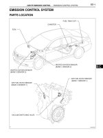
PARTS LOCATION
REAR VEHICLE
SPEED SENSOR LH
REAR VEHICLE
SPEED SENSOR RH
FRONT VEHICLE SPEED SENSOR LH
FRONT VEHICLE
SPEED SENSOR RH
TRANSMISSION CONTROL ECU (*1)
ECM (*2)
(*3)
*1: 2GR-FE
*2: 2AZ-FE
*3: U660E
THROTTLE BODY ASSEMBLY
SKID CONTROL ECU WITH ACTUATOR
ECM (*1)
- THROTTLE POSITION SENSOR
- THROTTLE CONTROL MOTOR
ENGINE ROOM R/B AND J/B
-ALT FUSE
-ST/AM2 FUSE
-FL MAIN FUSE
PARK / NEUTRAL
POSITION SWITCH
E129946E01
CRUISE CONTROL – CRUISE CONTROL SYSTEM
CC–3
CC
COMBINATION METER
- CRUISE MAIN INDICATOR LIGHT
*1: M/T
(*1)
INSTRUMENT PANEL J/B
-STOP FUSE
-IGN FUSE
DLC3
ACCELERATOR PEDAL
POSITION SENSOR
CLUTCH SWITCH
CRUISE CONTROL MAIN SWITCH
STOP LIGHT SWITCH
SPIRAL CABLE
E129947E01
CC–4
CRUISE CONTROL – CRUISE CONTROL SYSTEM
CC
SYSTEM DIAGRAM
Communication Table:
Sender Receiver Signal Line
ECM Combination Meter ECU
CRUISE main indicator operation
signal
CAN
:
Stop Light Switch
Park / Neutral Position
Switch (A/T)
CRUISE Main
Indicator Light
Vehicle Speed
Sensor
Skid Control ECU
Combination Meter
DLC3
Clutch Switch (M/T)
Cruise Main Switch
Accelerator Pedal
Position Sensor
Throttle Position
Sensor and Motor
Transmission Control
ECU (2GR-FE)
ECM
CAN
E129950E01
CRUISE CONTROL – CRUISE CONTROL SYSTEM
CC–5
CC
SYSTEM DESCRIPTION
1. CRUISE CONTROL SYSTEM
This system is controlled by the ECM, and is activated by
the throttle position sensor and motor. The ECM controls
the following functions: ON-OFF, - (COAST)/SET, +
(ACCEL)/RES (RESUME), CANCEL, vehicle speed
operation, motor output control, and overdrive control.
• The ECM compares the driving vehicle speed from
the speed sensor with the stored vehicle speed set
through the cruise control main switch. The ECM
instructs the throttle valve motor of the throttle body
assembly to close the valve when the driving speed is
greater than the stored speed, and instructs it to open
the valve when the driving speed is less than the
stored speed.
• The ECM receives signals such as ON-OFF, -
(COAST)/SET, + (ACCEL)/RES (RESUME), and
CANCEL from the cruise control main switch and
executes the command.
• The ECM illuminates the combination meter's
CRUISE main indicator light when it receives a cruise
control main switch ON signal.
• The ECM cancels the cruise control system when the
brake pedal is depressed and the ECM receives a
stop light switch signal.
• The ECM cancels the cruise control system when the
shift lever is moved from the D to the N position or the
transmission is shifted to the 3rd, 2nd, or 1st gear with
the shift lever in the S position, and the ECM receives
a park/neutral position switch signal.
• The ECM cancels the cruise control system when the
clutch pedal is depressed and the ECM receives a
clutch switch signal.
2. LIMIT CONTROL
(a) Low speed limit
The lowest possible limit of the speed setting range
is set at approximately 40 km/h (25 mph). The
cruise control system cannot be set when the
driving vehicle speed is below the low speed limit.
Cruise control operation will be automatically
canceled but the stored vehicle speed will be
retained when the vehicle speed drops below the
low speed limit 40 km/h (25 mph) while the cruise
control is in operation.
(b) High speed limit
The highest possible limit of the speed setting range
is set at approximately 200 km/h (125 mph). The
cruise control system cannot be set when the
driving vehicle speed is over the high speed limit.
Also, + (ACCEL)/RES (RESUME) cannot be used to
increase speed beyond the high speed limit.
CC–6
CRUISE CONTROL – CRUISE CONTROL SYSTEM
CC
3. OPERATION OF CRUISE CONTROL
The cruise control main switch operates 7 functions:
SET, - (COAST), TAP-DOWN, RES (RESUME), +
(ACCEL), TAP-UP, and CANCEL. The SET, TAP-DOWN,
and - (COAST) functions, and the RES (RESUME), TAP-
UP, and + (ACCEL) functions are operated with the
same switch. The cruise control main switch is an
automatic return type switch which turns on only while
operating it in the direction of each arrow and turns off
after releasing it.
(a) SET CONTROL
The vehicle speed is stored and constant speed
control is maintained when pushing the cruise
control main switch to - (COAST)/SET while driving
with the main switch on (the CRUISE main indicator
light is on), and the vehicle speed is within the set
speed range (between the low and high speed
limits).
(b) - (COAST) CONTROL
When the cruise control main switch is set to -
(COAST)/SET and held in that position while the
cruise control system is operating, the ECM sends a
"throttle valve opening angle 0°" demand signal to
the cruise control system. Then the vehicle speed,
when the cruise control main switch is released, is
stored and maintained.
HINT:
An actual throttle valve opening angle of 0° is not
possible due to the idle speed control, etc.
(c) TAP-DOWN CONTROL
When tapping down the cruise control main switch
to - (COAST)/SET (for approximately 0.6 seconds)
while the cruise control system is in operation, the
stored vehicle speed decreases each time by
approximately 1.6 km/h (1.0 mph). When the cruise
control main switch is released from - (COAST)/SET
and the difference between the driving and stored
vehicle speed is more than 5 km/h (3 mph), the
driving vehicle speed is stored and constant speed
control is maintained.
(d) ACCELERATION CONTROL
The throttle valve motor of the throttle body
assembly is instructed by the ECM to open the
throttle valve when + (ACCEL)/RES (RESUME) on
the cruise control main switch is pressed and held
while the cruise control system is in operation.
When the cruise control main switch is released
from + (ACCEL)/RES (RESUME), the vehicle speed
is stored and the vehicle is controlled at a constant
speed.
CRUISE CONTROL – CRUISE CONTROL SYSTEM
CC–7
CC
(e) TAP-UP CONTROL
When tapping up the cruise control main switch to +
(ACCEL)/RES (RESUME) (for approximately 0.6
seconds) while the cruise control system is in
operation, the stored vehicle speed increases each
time by approximately 1.6 km/h (1.0 mph). However,
when the difference between the driving and the
stored vehicle speed is more than 5 km/h
(approximately 3.1 mph), the stored vehicle speed
will not be changed.
(f) RESUME CONTROL
If cruise control operation was canceled with the
stop light switch or the CANCEL switch, and if
driving speed is within the limit range, pushing the
cruise control main switch to + (ACCEL)/RES
(RESUME) restores vehicle speed memorized at
the time of cancellation, and maintains constant
speed control.
(g) MANUAL CANCEL CONTROL
Performing any of the following cancels the cruise
control system while in operation (the stored vehicle
speed in the ECM is maintained).
• Depressing the brake pedal
• Depressing the clutch pedal
• The shift lever is moved from the D to the N
position or the transmission is shifted to the 3rd,
2nd, or 1st gear with the shift lever in the S
position.
• Pulling the cruise control main switch to CANCEL
• Turning the cruise control main switch off (the
stored vehicle speed in the ECM is not
maintained).
4. AUTO CANCEL (FAIL-SAFE)
This system has an automatic cancellation function (fail-
safe) (See page CC-16).
CC–8
CRUISE CONTROL – CRUISE CONTROL SYSTEM
CC
HOW TO PROCEED WITH
TROUBLESHOOTING
HINT:
• Use the following procedures to troubleshoot the cruise
control system.
• *: Use the intelligent tester.
NEXT
NEXT
Refer to PRECAUTION (See page CA-1).
(a) Check for output DTCs.
Result
HINT:
The ECM of this system is connected to the CAN
communication system. Therefore, before starting
troubleshooting, make sure to check that there is no
trouble in the CAN communication system.
B
A
Refer to DTC CHECK / CLEAR (See page CC-16).
NEXT
Result
1
VEHICLE BROUGHT TO WORKSHOP
2
PROBLEM SYMPTOM CONFIRMATION
3
CHECK CAN COMMUNICATION SYSTEM*
Result Proceed to
CAN DTC is not output A
CAN DTC is output B
PROCEED TO "CAN COMMUNICATION
SYSTEM"
4
DTC CHECK AND CLEAR*
5
DTC CHECK (OTHER THAN CAN SYSTEM DTC)*
Result Proceed to
DTC is not output A
DTC is output B
CRUISE CONTROL – CRUISE CONTROL SYSTEM
CC–9
CC
A
B
Refer to DIAGNOSTIC TROUBLE CODE CHART (See page
CC-18).
NEXT
Result
A
B
Refer to ELECTRONIC CIRCUIT INSPECTION
PROCEDURE (See page IN-40).
NEXT
Refer to the PROBLEM SYMPTOMS TABLE (See page CC-
11).
NEXT
NEXT
Refer to TERMINALS OF ECM (See page CC-13).
GO TO STEP 7
6
DTC CHART
GO TO STEP 10
7
PROBLEM SYMPTOM CONFIRMATION
Result Proceed to
Symptom occurs A
Symptom does not occur B
GO TO STEP 9
8
SYMPTOM SIMULATION
Go to step 7
9
PROBLEM SYMPTOMS TABLE
10
CIRCUIT INSPECTION
11
TERMINALS OF ECM
CC–10
CRUISE CONTROL – CRUISE CONTROL SYSTEM
CC
NEXT
NEXT
NEXT
NEXT
ROAD TEST
1. PROBLEM SYMPTOM CONFIRMATION
(a) Inspect the SET function.
(1) Turn the cruise control main switch on.
(2) Drive at the required speed (40 km/h (25 mph)
or higher).
(3) Push the cruise control main switch to -
(COAST)/SET.
(4) After releasing the switch, check that the vehicle
cruises at the set speed.
(b) Inspect the ACCELERATION function.
(1) Turn the cruise control main switch on.
(2) Drive at the required speed (40 km/h (25 mph)
or higher).
(3) Push the cruise control main switch to -
(COAST)/SET.
(4) Check that vehicle speed increases while the
cruise control main switch is pushed to +
(ACCEL)/RES (RESUME), and that the vehicle
cruises at the newly set speed when the switch
is released.
(5) Push the cruise control main switch to +
(ACCEL)/RES (RESUME) and then release it
immediately. Check that vehicle speed increases
by approximately 1.6 km/h (1.0 mph) (tap-up
control).
12
IDENTIFICATION OF PROBLEM
13
REPAIR OR REPLACE
14
CONFIRMATION TEST
END
E107085
E107086
CRUISE CONTROL – CRUISE CONTROL SYSTEM
CC–11
CC
(c) Inspect the - (COAST) function.
(1) Turn the cruise control main switch on.
(2) Drive at the required speed between 40 km/h
(25 mph) and 200 km/h (125 mph).
(3) Push the cruise control main switch to -
(COAST)/SET.
(4) Check that vehicle speed decreases while the
cruise control main switch is pushed to -
(COAST)/SET, and the vehicle cruises at the
newly set speed when the switch is released.
(5) Push the cruise control main switch to -
(COAST)/SET, and then release it immediately.
Check that vehicle speed decreases by
approximately 1.6 km/h (1.0 mph) (tap-down
control).
(d) Inspect the CANCEL function.
(1) Turn the cruise control main switch on.
(2) Drive at the required speed between 40 km/h
(25 mph) and 200 km/h (125 mph).
(3) Push the cruise control main switch to -
(COAST)/SET.
(4) When performing any one of the following,
check that the cruise control system is canceled
and that the normal driving mode is reset.
• Depressing the brake pedal
• Depressing the clutch pedal
• The shift lever is moved from the D to the N
position or the transmission is shifted to the
3rd, 2nd, or 1st gear with the shift lever in the
S position
• Turning the cruise control main switch off
• Pulling the cruise control main switch to
CANCEL
(e) Inspect the RES (RESUME) function.
(1) Turn the cruise control main switch on.
(2) Drive at the required speed between 40 km/h
(25 mph) and 200 km/h (125 mph).
(3) Push the cruise control main switch to -
(COAST)/SET.
(4) Cancel the cruise control system by performing
any of the above operations (other than turning
the main switch off).
(5) After pushing the cruise control main switch to +
(ACCEL)/RES (RESUME) at a driving speed of
more than 40 km/h (25 mph), check that the
vehicle resumes the speed set prior to the
cancellation.
E107085
E107087
E107086
CC–12
CRUISE CONTROL – CRUISE CONTROL SYSTEM
CC
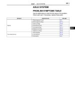
PROBLEM SYMPTOMS TABLE
HINT:
Be sure to perform the SYMPTOM SIMULATION procedure
before replacing the ECM. If these symptoms do not persist,
the cause of the problem may be poor intermittent electrical
contact (open or short) of a wire harness or connector.
Cruise control system:
Symptom Suspected area See page
Vehicle speed cannot be set. (The CRUISE main
indicator light comes on.)
1. Cruise control switch circuit CC-28
2. Combination meter ME-15
3. Vehicle speed sensor circuit CC-19
4. Stop light switch CC-20
5. Transmission range sensor circuit (U250E) AX-39
5. Park / Neutral position sensor circuit (U660E) AX-158
6. Clutch switch circuit CC-25
7. If the symptoms still occur after the above ares have been
inspected and have proven to be normal, replace the ECM.
(2AZ-FE)
ES-432
7. If the symptoms still occur after the above ares have been
inspected and have proven to be normal, replace the ECM.
(2GR-FE)
ES-518
Pushing the ON-OFF button does not turn the cruise
control system on. (Vehicle speed cannot be set.)
1. Stop light switch circuit CC-20
2. Clutch switch circuit (M/T) CC-25
3. Vehicle speed sensor circuit CC-19
4. Cruise control switch circuit CC-28
5. Transmission range sensor circuit (U250E) AX-39
5. Park / Neutral position sensor circuit (U660E) AX-158
6. If the symptoms still occur after the above areas have been
inspected and have proven to be normal, replace the ECM.
(2AZ- FE)
ES-432
6. If the symptoms still occur after the above areas have been
inspected and have proven to be normal, replace the ECM.
(2GR-FE)
ES-518
The cruise control is canceled while it is operating.
1. Stop light switch circuit CC-20
2. Clutch switch circuit (M/T) CC-25
3. Transmission range sensor circuit (U250E) AX-39
3. Park / Neutral position sensor circuit (U660E) AX-158
4. Cruise control switch circuit CC-28
5. Vehicle speed sensor circuit CC-19
6. Combination meter ME-15
7. If the symptoms still occur after the above areas have been
inspected and have proven to be normal, replace the ECM.
(2AZ-FE)
ES-432
7. If the symptoms still occur after the above areas have been
inspected and have proven to be normal, replace the ECM.
(2GR-FE)
ES-518
Pulling back on the control main switch does not
cancel the cruise control. (The CRUISE main indicator
light remains on.)
1. Cruise control switch circuit CC-28
2. If the symptoms still occur after the above area has been
inspected and has proven to be normal, replace the ECM.
(2AZ-FE)
ES-432
2. If the symptoms still occur after the above area has been
inspected and has proven to be normal, replace the ECM.
(2GR-FE)
ES-518
Pulling back on the control main switch does not
cancel the cruise control. (The CRUISE main indicator
light goes off.)
Replace ECM (2AZ-FE) ES-432
Replace ECM (2GR-FE) ES-518
CRUISE CONTROL – CRUISE CONTROL SYSTEM
CC–13
CC
The cruise control is not canceled when vehicle speed
drops below the low speed limit. (The CRUISE main
indicator light remains on.)
1. Vehicle speed sensor circuit CC-19
2. If the symptoms still occur after the above area has been
inspected and has proven to be normal, replace the ECM.
(2AZ-FE)
ES-432
2. If the symptoms still occur after the above area has been
inspected and has proven to be normal, replace the ECM.
(2GR-FE)
ES-518
The cruise control is not canceled when vehicle speed
drops below the low speed limit. (The CRUISE main
indicator light goes off.)
Replace ECM (2AZ-FE) CC-13
Replace ECM (2GR-FE) ES-518
Depressing the brake pedal does not cancel the cruise
control. (The CRUISE main indicator light remains on.)
1. Stop light switch circuit CC-20
2. If the symptoms still occur after the above area has been
inspected and has proven to be normal, replace the ECM.
(2AZ-FE)
ES-432
2. If the symptoms still occur after the above area has been
inspected and has proven to be normal, replace the ECM.
(2GR-FE)
ES-518
Depressing the brake pedal does not cancel the cruise
control. (The CRUISE main indicator light goes off.)
Replace ECM (2AZ-FE) ES-432
Replace ECM (2GR-FE) ES-518
Depressing the clutch pedal does not cancel the cruise
control. (The CRUISE main indicator light remains on.)
1. Clutch switch circuit CC-25
2. If the symptoms still occur after the above area has been
inspected and has proven to be normal, replace the ECM.
(2AZ-FE)
ES-432
2. If the symptoms still occur after the above area has been
inspected and has proven to be normal, replace the ECM.
(2GR-FE)
ES-518
Depressing the clutch pedal does not cancel the cruise
control. (The CRUISE main indicator light goes off.)
Replace ECM (2AZ-FE) ES-432
Replace ECM (2GR-FE) ES-518
Moving the shift liver does not cancel the cruise
control.
1. Transmission range sensor circuit (U250E) AX-39
1. Park / Neutral position sensor circuit (U660E) AX-158
2. If the symptoms still occur after the above area has been
inspected and has proven to be normal, replace the ECM.
(2AZ-FE)
ES-432
2. If the symptoms still occur after the above area has been
inspected and has proven to be normal, replace the ECM.
(2GR-FE)
ES-518
Hunting (Speed is not constant.)
1. Vehicle speed sensor circuit CC-19
2. Combination meter ME-15
3. If the symptoms still occur after the above ares have been
inspected and have proven to be normal, replace the ECM.
(2AZ-FE)
ES-432
3. If the symptoms still occur after the above ares have been
inspected and have proven to be normal replace the ECM.
(2GR-FE)
ES-518
The CRUISE main indicator light remains blinking.
1. TC and CG terminal circuit CC-35
2. If the symptoms still occur after the above area has been
inspected and has proven to be normal, replace the ECM.
CC-13
Symptom Suspected area See page
CC–14
CRUISE CONTROL – CRUISE CONTROL SYSTEM
CC
TERMINALS OF ECM
1. CHECK ECM
HINT:
*1: 2GR-FE
*2: 2AZ-FE
Symbols (Terminal No.) Wiring Color Terminal Description Condition Specified Condition
A55-27 (TC) - C55-81 (E1)
*1
A24-27 (TC) - C24-104 (E1)
*2
P - W-B Ground Ignition switch on (IG) 10 to 14 V
A55-27 (TC) - C55-81 (E1)
*1
A24-27 (TC) - C24-104 (E1)
*2
P - W-B Ground
Connect terminals TC and
CG of DLC3
Below 1 V
A55-36 (STP) - C55-81 (E1)
*1
A24-36 (STP) - C24-104 (E1)
*2
W - W-B Stop light signal
Ignition switch on (IG),
Depress brake pedal
10 to 14 V
A55-36 (STP) - C55-81 (E1)
*1
A24-36 (STP) - C24-104 (E1)
*2
W - W-B Stop light signal
Ignition switch on (IG),
Release brake pedal
Below 1 V
A55-40 (CCS) - C55-81 (E1)
*1
A24-40 (CCS) - C24-104 (E1)
*2
W - W-B
Cruise control main switch
circuit
Ignition switch on (IG) 10 to 14 V
A55-40 (CCS) - C55-81 (E1)
*1
A24-40 (CCS) - C24-104 (E1)
*2
W - W-B
Cruise control main switch
circuit
CANCEL switch ON 6.6 to 10.1 V
A55-40 (CCS) - C55-81 (E1)
*1
A24-40 (CCS) - C24-104 (E1)
*2
W - W-B
Cruise control main switch
circuit
SET/COAST switch ON 4.5 to 7.1 V
A55-40 (CCS) - C55-81 (E1)
*1
A24-40 (CCS) - C24-104 (E1)
*2
W - W-B
Cruise control main switch
circuit
RES/ACC switch ON 2.3 to 4.0 V
A55-40 (CCS) - C55-81 (E1)
*1
A24-40 (CCS) - C24-104 (E1)
*2
W - W-B
Cruise control main switch
circuit
MAIN switch ON Below 1 V
A55-35 (ST1-) - C55-81 (E1)
*1
A24-35 (ST1-) - C24-104 (E1)
*2
GR - W-B Stop light signal
Ignition switch on (IG),
Depress brake pedal
Below 1 V
A55-35 (ST1-) - C55-81 (E1)
*1
A24-35 (ST1-) - C24-104 (E1)
*2
GR - W-B Stop light signal
Ignition switch on (IG),
Release brake pedal
10 to 14 V
C24-56 (D) - C55-81 (E1)
*1
C24-56 (D) - C24-104 (E1)
*2
C - W-B Clutch signal
Ignition switch on (IG),
Depress clutch pedal
Below 1 V
C24-56 (D) - C55-81 (E1)
*1
C24-56 (D) - C24-104 (E1)
*2
C - W-B Clutch signal
Ignition switch on (IG),
Release brake pedal
10 to 14 V
C55
C24
A55
A24
*1 *1
*2 *2
*1: 2GR-FE
*2: 2AZ-FE
A107881E45
CRUISE CONTROL – CRUISE CONTROL SYSTEM
CC–15
CC
DIAGNOSIS SYSTEM
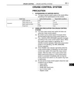
1. DESCRIPTION
The ECU controls the cruise control system of the
vehicle. The data and DTCs relating to the cruise control
system can be read from the DLC3 of the vehicle. If
either DTC or CRUISE OK is not displayed on the multi-
information display on the combination meter when
checking for DTCs, there may be a problem with either
the combination meter or the CAN communication and
multiplex communication systems. Use the intelligent
tester to check and solve the problem.
2. CHECK DLC3
(a) The ECU uses the ISO 15765-4 for communication
protocol. The terminal arrangement of the DLC3
complies with SAE J1962 and matches the ISO
15765-4 format.
NOTICE:
*: Before measuring the resistance, leave the
vehicle as is for at least 1 minute and do not
operate the ignition switch, any other switches
or the doors.
If the result is not as specified, the DLC3 may have
a malfunction. Repair or replace the harness and
connector.
(b) Connect the cable of the intelligent tester to the
DLC3, turn the ignition switch on (IG), and attempt
to use the tester. If the display indicates that a
communication error has occurred, there is a
problem with either the vehicle or the tester.
• If communication is normal when the tester is
connected to another vehicle, inspect the DLC3
of the original vehicle.
CG
SG
BAT
SIL
CANH
CANL
H100769E16
Terminal No. (Symbols) Terminal Description Condition Specified Condition
SIL (7) - SG (5) Bus "+" line During transmission Pulse generation
CG (4) - Body ground Chassis ground Always Below 1 Ω
SG (5) - Body ground Signal ground Always Below 1 Ω
BAT (16) - Body ground Battery positive Always 10 to 14 V
CANH (6) - CANL (14) CAN bus line
Ignition switch off
*
54 to 69 Ω
CANH (6) - CG (4) HIGH-level CAN bus line
Ignition switch off
*
200 Ω or higher
CANL (14) - CG (4) LOW-level CAN bus line
Ignition switch off
*
200 Ω or higher
CANH (6) - BAT (16) HIGH-level CAN bus line
Ignition switch off
*
6 kΩ or higher
CANL (14) - BAT (16) LOW-level CAN bus line
Ignition switch off
*
6 kΩ or higher
CC–16
CRUISE CONTROL – CRUISE CONTROL SYSTEM
CC
• If communication is still not possible when the
tester is connected to another vehicle, the
problem may be in the tester itself. Consult the
Service Department listed in the tester's
instruction manual.
3. CHECK INDICATOR
(a) Turn the ignition switch on (IG).
(b) Check that the CRUISE main indicator light
illuminates when the cruise control main switch is
turned on, and that the indicator light turns off when
the main switch is turned off. If the results are not as
specified, inspect the CRUISE main indicator light
circuit (See page CC-34).
HINT:
While driving with cruise control, the ECM activates
AUTO CANCEL of the cruise control system when a
malfunction occurs in one of the following: vehicle
speed sensors, stop light switch, or other related
parts. When AUTO CANCEL is activated, the
CRUISE main indicator light outputs the blinking
pattern shown to the left. At the same time, data of
the malfunction is stored as a DTC.
DTC CHECK / CLEAR
1. DTC CHECK
(a) Connect the intelligent tester to the DLC3.
(1) Connect the intelligent tester to the Controller
Area Network Vehicle Interface Module (CAN
VIM). Then connect the CAN VIM to the Data
Link Connector 3 (DLC3).
(b) Turn the ignition switch on (IG).
(c) Read the DTCs by following the prompts on the
tester screen.
HINT:
Refer to the intelligent tester operator's manual for
further details.
2. DTC CLEAR
(a) Connect the intelligent tester to the DLC3.
(b) Turn the ignition switch on (IG).
(c) Operate the intelligent tester to erase the codes.
HINT:
Refer to the intelligent tester operator's manual for
further details.
CRUISE Main
Indicator Light
E129948E01
CRUISE Main Indicator Light
1.5 sec. 0.5 sec.
ON
OFF
BE04034E23
Intelligent Tester
DLC3
C131977E04
CRUISE CONTROL – CRUISE CONTROL SYSTEM
CC–17
CC
FAIL-SAFE CHART
HINT:
If the following conditions are detected while the cruise
control is in operation, the system clears the stored vehicle
speed in the ECM and cancels the cruise control operation.
Vehicle Condition Auto Cancel Condition Re-operation Condition
CRUISE main indicator light blinks
• There is open or short in stop light switch
circuit
• There is problem with vehicle speed
signal
• There is problem with throttle position
sensor and motor
Turn cruise control main switch on again
CRUISE main indicator light blinks
• There is problem with input circuit of stop
light switch circuit
• There is problem with cancel circuit
• Turn cruise control main switch on again
• Turn ignition switch off then on again
CRUISE main indicator light remains on
(Cruise control is canceled)
• Vehicle speed is lower than low speed
limit (approx. 40 km/h (25 mph)) while
running with cruise control on
Push cruise control main switch to +
(ACCEL)/RES (RESUME)
• Vehicle speed is lower than stored speed
by approx. 16 km/h (9.9 mph) or more
Push cruise control main switch to - (COAST)/
SET
CC–18
CRUISE CONTROL – CRUISE CONTROL SYSTEM
CC
DATA LIST / ACTIVE TEST
1. READ DATA LIST
HINT:
Using the intelligent tester's DATA LIST allows switch,
sensor, actuator, and other item values to be read
without removing any parts. Reading the DATA LIST
early in troubleshooting is one way to save time.
(a) Connect the intelligent tester to the DLC3.
(b) Turn the ignition switch on (IG).
(c) Read the DATA LIST according to the display on the
tester.
ECM (Cruise control):
HINT:
• "1" is OK but CRUISE main indicator light does
not illuminate → CRUISE main indicator light,
wire harness, or ECM failure
Item
Measurement Item / Display
(Range)
Normal Condition Diagnostic Note
VEHICLE SPD
Vehicle speed / min.: 0 km/h (0
mph), max.: 255 km/h (158 mph)
Actual vehicle speed -
MEMORY SPD
Cruise control memorized speed /
min.: 36 km/h (22.5 mph), max.:
200 km/h (125 mph)
Actual stored vehicle speed -
THROTTLE
Throttle opening angle / min.: 0°,
max.: 125°
Actual demanded throttle angle -
SHIFT D POS Shift D position / ON or OFF
ON: Shift lever in D or 4
OFF: Shift lever is except D or 4
position
-
CRUISE CONTROL
Cruise control system active
condition / ON or OFF
ON: Cruise control activated
OFF: Cruise control deactivated
-
CCS INDICATOR M
Cruise indicator signal (Main
CPU) / ON or OFF
ON: "CRUISE" on
OFF: "CRUISE" off
-
MAIN SW (MAIN)
Main switch signal (Main CPU) /
ON or OFF
ON: Cruise control main switch
on
OFF: Cruise control main switch
off
"1"
MAIN SW (SUB)
Main switch signal (Main CPU) /
ON or OFF
ON: Cruise control main switch
on
OFF: Cruise control main switch
off
-
SHIFT D POS Clutch pedal / ON or OFF
ON: Clutch pedal released
OFF: Clutch pedal depressed
-
CANCEL SW
CANCEL switch signal / ON or
OFF
ON: CANCEL switch on
OFF: CANCEL switch off
-
SET/COAST SW
SET / COAST switch signal / ON
or OFF
ON: - (COAST) / SET switch on
OFF: - (COAST) / SET switch off
-
RES/ACC SW
RES / ACC switch signal / ON or
OFF
ON: + (ACCEL) / RES (RESUME)
switch on
OFF: + (ACCEL) / RES
(RESUME) switch off
-
STP LIGHT SW M (STP)
Stop light switch signal (Main
CPU) / ON or OFF
ON: Brake pedal depressed
OFF: Brake pedal released
-
STP LIGHT SW S2 (STP)
Stop light switch signal (Sub
CPU) / ON or OFF
ON: Brake pedal depressed
OFF: Brake pedal released
-
STP LIGHT SW S1 (ST1-)
Stop light switch signal (Sub
CPU)
ON: Brake pedal depressed
OFF: Brake pedal released
-
CRUISE CONTROL – CRUISE CONTROL SYSTEM
CC–19
CC
2. PERFORM ACTIVE TEST
HINT:
Performing the intelligent tester's ACTIVE TEST allows
relays, VSVs, actuators, and other items to be operated
without removing any parts. Performing the ACTIVE
TEST early in troubleshooting is one way to save time.
The DATA LIST can be displayed during the ACTIVE
TEST.
(a) Connect the intelligent tester to the DLC3.
(b) Turn the ignition switch on (IG).
(c) Perform the ACTIVE TEST according to the display
on the tester.
HINT:
The ignition switch must be turned on (IG) to
proceed to with the ACTIVE TEST using the
intelligent tester.
Combination meter:
Item Vehicle Condition / Test Details Diagnostic Note
CRUISE INDIC Turns CRUISE main indicator light ON / OFF -
CC–20
CRUISE CONTROL – CRUISE CONTROL SYSTEM
CC
DIAGNOSTIC TROUBLE CODE CHART
If a trouble code is displayed during the DTC check, check
the trouble areas listed for that code in the table below and
proceed to the appropriate page.
Cruise control system:
DTC No. Detection Item Trouble Area See page
P0500 Vehicle Speed Sensor
Malfunction
1. Vehicle speed sensor
2. Vehicle speed sensor signal
circuit
3. ECM
CC-19
P0503 Vehicle Speed Sensor "A"
Intermittent / Erratic / High
1. Vehicle speed sensor
2. Vehicle speed sensor signal
circuit
3. ECM
CC-19
P0571 Brake Switch "A" Circuit 1. Stop light switch
2. Stop light switch circuit
3. ECM
CC-20
P0607 Control Module Performance ECM CC-24
CRUISE CONTROL – CRUISE CONTROL SYSTEM
CC–21
CC
DESCRIPTION
Refer to DTC P0500 (See page ES-229).
WIRING DIAGRAM
Refer to DTC P0500 (See page ES-231).
INSPECTION PROCEDURE
Refer to DTC P0500 (See page ES-231).
DTC P0500 Vehicle Speed Sensor Malfunction
DTC P0503
Vehicle Speed Sensor "A" Intermittent / Erratic /
High
DTC No. DTC Detection Condition Trouble Area
P0500
The vehicle speed signal from the vehicle speed sensor
is cut for 0.14 sec. or more while cruise control is in
operation.
• Vehicle speed sensor
• Vehicle speed sensor signal circuit
•ECM
P0503
Momentary interruption and noise are detected when a
rapid change of vehicle speed occurs while cruise
control is in operation.
• Vehicle speed sensor
• Vehicle speed sensor signal circuit
•ECM
CC–22
CRUISE CONTROL – CRUISE CONTROL SYSTEM
CC
DESCRIPTION
When the brake pedal is depressed, the stop light switch sends a signal to the ECM. When the ECM
receives this signal, it cancels the cruise control. The fail-safe function operates to enable normal driving
even if there is a malfunction in the stop light signal circuit. The cancellation condition occurs when
voltage is applied to terminal STP. When the brake is applied, voltage is normally applied to terminal STP
of the ECM through the STOP SW fuse and the stop light switch, and the ECM turns the cruise control off.
WIRING DIAGRAM
DTC P0571 Brake Switch "A" Circuit
DTC No. DTC Detection Condition Trouble Area
P0571
When voltage of STP terminal and that of ST1- terminal
of ECM are less than 1 V for 0.5 sec. or more
• Stop light switch
• Stop light switch circuit
•ECM
ECM
A55
A55
A24
A24
35
3636
35
A19
Stop Light Switch
12
43
STOP
IGN
ST/AM2
ALT
FL MAIN
Battery
56
AM2
IG2
ST2
STP
ST1-
Ignition Switch
Without Smart Key System:
*1
*1
*2
*2
*1: 2GR-FE
*2: 2AZ-FE
E129952E01
CRUISE CONTROL – CRUISE CONTROL SYSTEM
CC–23
CC
INSPECTION PROCEDURE
(a) Connect the intelligent tester to the DLC3.
(b) Turn the ignition switch on (IG), and turn the intelligent
tester main switch on.
(c) Check the DATA LIST for proper functioning of the stop
light switch.
ECM (Cruise control):
OK:
When the brake pedal is operated, the display
changes as shown above.
OK
NG
1
READ VALUE ON INTELLIGENT TESTER
ECM
A55
A55A24
A24
Stop Light Switch
A19
12
43
STOP SW
IGN
ALT
IG
IG2 MAIN
RHJ/B-AM
Battery
With Smart Key System:
STP
ST1-
*1
36
*2
36
*2
35
*1
35
*1: 2GR-FE
*2: 2AZ-FE
E129951E01
Item
Measurement Item / Display
(Range)
Normal Condition Diagnostic Note
STP LIGHT SW M (STP)
Stop light switch signal (Main
CPU) / ON or OFF
ON: Brake pedal depressed
OFF: Brake pedal released
-
STP LIGHT SW S2 (STP)
Stop light switch signal (Sub
CPU) / ON or OFF
ON: Brake pedal depressed
OFF: Brake pedal released
-
STP LIGHT SW S1 (ST1-)
Stop light switch signal (Sub
CPU) / ON or OFF
ON: Brake pedal depressed
OFF: Brake pedal released
-
REPLACE ECM
CC–24
CRUISE CONTROL – CRUISE CONTROL SYSTEM
CC
(a) Disconnect the A19 connector from the stop light switch.
(b) Measure the voltage according to the value(s) in the
table below.
Standard voltage
NG
OK
(a) Remove the stop light switch. (See page CC-42)
(b) Measure the resistance according to the value(s) in the
table below.
Standard resistance
(c) Install the stop light switch.
NG
OK
2
CHECK HARNESS AND CONNECTOR (STOP LIGHT SWITCH - BATTERY)
A19
Stop Light Switch Wire Harness
Side Connector Front View:
E114084E08
Tester Connection Condition Specified Condition
A19-2 - Body ground Always 10 to 14 V
A19-3 - Body ground Ignition switch on (IG) 10 to 14 V
REPAIR OR REPLACE HARNESS OR
CONNECTOR
3
INSPECT STOP LIGHT SWITCH
Not
Pushed
Pushed
Stop Light Switch:
E128781E02
Tester Connection Switch Condition Specified Condition
1 - 2 Switch pin not pushed Below 1 Ω
3 - 4 Switch pin not pushed 10 kΩ or higher
1 - 2 Switch pin pushed 10 kΩ or higher
3 - 4 Switch pin pushed Below 1 Ω
REPLACE STOP LIGHT SWITCH
CRUISE CONTROL – CRUISE CONTROL SYSTEM
CC–25
CC
(a) Reconnect the stop light switch connector.
(b) Disconnect the A55 connector from the ECM. (2GR-FE)
(c) Disconnect the A24 connector from the ECM. (2AZ-FE)
(d) Turn the ignition switch on (IG).
(e) Measure the voltage according to the value(s) in the
table below.
Standard voltage
HINT:
*1: 2GR-FE
*2: 2AZ-FE
NG
OK
4
CHECK ECM
A55
STP
ST1-
ECM Wire Harness View:
A24
*1
*2
*1: 2GR-FE
*2: 2AZ-FE
E126835E03
Tester Connection Brake Pedal Condition Specified Condition
A55-36 (STP) - Body
ground
*1
A24-36 (STP) - Body
ground
*2
Depressed 10 to 14 V
A55-36 (STP) - Body
ground
*1
A24-36 (STP) - Body
ground
*2
Released Below 1 V
A55-35 (ST1-) - Body
ground
*1
A24-35 (ST1-) - Body
ground
*2
Depressed Below 1 V
A55-35 (ST1-) - Body
ground
*1
A24-35 (ST1-) - Body
ground
*2
Released 10 to 14 V
REPAIR OR REPLACE HARNESS OR
CONNECTOR (STOP LIGHT SWITCH - ECM)
REPLACE ECM