Toyota camry 2006 2011 door lock hệ thống khóa cửa trên toyota camry đời 2006 2011
Bạn đang xem bản rút gọn của tài liệu. Xem và tải ngay bản đầy đủ của tài liệu tại đây (7.52 MB, 269 trang )
DOOR LOCK – POWER DOOR LOCK CONTROL SYSTEM
DL–1
DL
POWER DOOR LOCK CONTROL
SYSTEM
PRECAUTION
1. EXPRESSIONS OF IGNITION SWITCH
(a) The type of ignition switch used on this model differs
according to the specifications of the vehicle.
The expressions listed in the table below are used
in this section.
Switch Type Ignition Switch (position) Engine Switch (condition)
Expression
Ignition switch off LOCK Off
Ignition switch on (IG) ON On (IG)
Ignition switch on (ACC) ACC On (ACC)
Engine start START Start
DL–2
DOOR LOCK – POWER DOOR LOCK CONTROL SYSTEM
DL
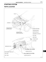
PARTS LOCATION
LUGGAGE DOOR LOCK
FRONT DOOR LOCK
REAR DOOR LOCK
FRONT DOOR COURTESY SWITCH
REAR DOOR COURTESY SWITCH
B112603E01
DOOR LOCK – POWER DOOR LOCK CONTROL SYSTEM
DL–3
DL
DOOR CONTROL SWITCH
DOOR CONTROL SWITCH
UNLOCK WARNING SWITCH
DLC3
INSTRUMENT PANEL J/B
- MAIN BODY ECU
SHIFT LOCK CONTROL ECU (*2)
*1: W/O SMART KEY SYSTEM
*2: W/ SMART KEY SYSTEM
(MUTIPLEX NETWORK
MASTER SWITCH)
(*1)
B112602E01
DL–4
DOOR LOCK – POWER DOOR LOCK CONTROL SYSTEM
DL
SYSTEM DIAGRAM
Transmitting ECU (Transmitter) Receiving ECU (Receiver) Signals Communication method
ECM Main Body ECU
Park / Neutral Position Switch
Signal
CAN (MS bus)
Door Lock Control System:
Main Body ECU (Instrument Panel J/B)
Multiplex Network Master Switch Assembly
- Manual Door Lock Switch (Driver Side)
Front Door Lock Assembly LH
- Door Key Lock and Unlock Switch
- Door Lock Motor
- Door Unlock Detection Switch
Rear Door Lock Assembly LH
- Door Lock Motor
- Door Unlock Detection Switch
Front Door Courtesy Switch Assembly LH
Rear Door Courtesy Switch Assembly LH
Luggage Compartment Door Lock Assembly
- Luggage Compartment Door
Courtesy Switch
- Door Lock Motor
: CAN Communication Line (MS bus)
Front Passenger Side Door Control Switch
Assembly
Front Door Lock Assembly RH
- Door Key Lock and Unlock Switch
- Door Lock Motor
- Door Unlock Detection Switch
Rear Door Lock Assembly RH
- Door Lock Motor
- Door Unlock Detection Switch
Front Door Courtesy Switch Assembly RH
Rear Door Courtesy Switch Assembly RH
Unlock Warning Switch (*1)
Shift Lock Control ECU (*2)
*1: w/o Smart Key System
*2: w/ Smart Key System
ECM
B112604E01
DOOR LOCK – POWER DOOR LOCK CONTROL SYSTEM
DL–5
DL
SYSTEM DESCRIPTION
1. POWER DOOR LOCK CONTROL SYSTEM
DESCRIPTION
(a) The power door lock system locks/unlocks all the
doors.
The master switch and the door control switch on
the passenger door send "lock/unlock" request
signals to the main body ECU. Then, the main body
ECU sends these request signals to the lock motors
in each door to lock/unlock all the doors at once in
response to the inputs.
Operating the driver's door lock using a mechanical
key sends request signals to lock/unlock the doors
to the main body ECU via the master switch. "2-step
unlock function" is optional for unlocking procedures
of the key-linked lock for the driver side door.
2. FUNCTION OF MAIN COMPONENT
3. SYSTEM FUNCTION
HINT:
The following functions' default settings are ON. Some of
these functions can be customized (See page DL-10).
(a) This system is controlled by the main body ECU.
The main body ECU outputs signals to each door
lock motor. The door lock control system of the
CAMRY has the following functions:
Components Function
Multiplex network master switch assembly (Manual door lock switch)
Door control switch on master switch assembly locks/unlocks all
doors.
Door control switch Door control switch on passenger side door locks/unlocks all doors.
Door courtesy switch
Placed on each door. Detects door status (open or closed) and
outputs data to main body ECU. Turns on when door is open and turns
off when door is closed.
Driver side door lock
• Built-in motor locks/unlocks door.
• Built-in door control switch (key-linked) detects door key
operation's door status (locked or unlocked) and outputs data to
main body ECU.
• Built-in position switch detects door status (locked or unlocked)
and outputs data to main body ECU. This switch turns off when
door is locked and turns on when door is unlocked.
Front passenger side door lock, luggage compartment door lock, rear
LH and RH door locks
• Built-in motor locks/unlocks door.
• Built-in position switch detects door status (locked or unlocked)
and outputs data to main body ECU. This switch turns off when
door is locked and turns on when door is unlocked.
Function Outline
Manual lock and unlock function
This function can lock or unlock all doors by the door lock control
switch operation.
Key-linked lock and unlock function
This function, which is linked with the key cylinder, can lock or unlock
all the doors when a lock or unlock operation is effected.
Manual unlock prohibition function
Performing the door lock operation with an electrical key (*1) or a
mechanical key (transmitter) will prohibit the unlock operation by the
door lock control switch.
Key lock-in prevention function (Electrical key)
If a each door lock (*1) or driver's door lock (*2) operation is
performed when the electrical key (*1) or mechanical key is in the
cabin (*1) or ignition key cylinder (*2), all the doors will be unlocked.
DL–6
DOOR LOCK – POWER DOOR LOCK CONTROL SYSTEM
DL
*1: w/ Smart Key System
*2: w/o Smart Key System
Shift-linked automatic door lock function (A/T)
When the conditions listed below are met consecutively, this function
causes all the doors to be automatically locked.
• The ignition switch is on (IG).
• All doors are closed.
• The shift lever is moved out of the P position.
• Any of the doors are unlocked.
Shift-linked automatic door unlock function (A/T)
When the ignition switch is on (IG), if moving the shift lever to the P
position from any other position, all the doors will be automatically
unlocked.
One-motion open
When the door is locked, this function enables the door to be
unlocked by pulling the inside handle of the driver's or front
passenger's door.
2-step unlock function
This function is provided to unlock the driver's door by turning the key
cylinder once and to unlock the remaining doors by turning it the
second time.
Function Outline
DOOR LOCK – POWER DOOR LOCK CONTROL SYSTEM
DL–7
DL
HOW TO PROCEED WITH
TROUBLESHOOTING
HINT:
• Use the following procedures to troubleshoot the power
door lock control system.
• The intelligent tester should be used in step 5 and 7.
NEXT
HINT:
• In troubleshooting, confirm that the problem symptoms
have been accurately identified. Preconceptions should be
discarded in order to make an accurate judgment. To
clearly understand what the problem symptoms are, it is
extremely important to ask the customer about the
problem and the conditions at the time the malfunction
occurred.
• Gather as much information as possible for reference.
Past problems that seem unrelated may also help in some
cases.
• The following 5 items are important points in the problem
analysis:
NEXT
Standard Voltage:
11 to 14 V
If the voltage is below 11 V, recharge or replace the
battery before proceeding to the next step.
NEXT
Result
1
VEHICLE BROUGHT TO WORKSHOP
2
CUSTOMER PROBLEM ANALYSIS CHECK
What Vehicle model, system name
When Date, time, occurrence frequency
Where Road conditions
Under what conditions? Running conditions, driving conditions, weather conditions
How did it happen? Problem symptoms
3
INSPECT BATTERY VOLTAGE
4
PROBLEM SYMPTOMS TABLE
Result Proceed to
Fault is not listed in problem symptoms table A
Fault is listed in problem symptoms table B
DL–8
DOOR LOCK – POWER DOOR LOCK CONTROL SYSTEM
DL
B
A
(a) Terminals of ECU
(See page DL-13)
(b) DATA LIST/ACTIVE TEST
(See page DL-17)
NEXT
NEXT
NEXT
After repair, go to step 7
5
OVERALL ANALYSIS AND TROUBLESHOOTING
6
REPAIR OR REPLACE
7
CONFIRMATION TEST
END
DOOR LOCK – POWER DOOR LOCK CONTROL SYSTEM
DL–9
DL
OPERATION CHECK
1. CHECK ELECTRICAL DOOR LOCK OPERATION
NOTICE:
The initial condition that the customizing function
using the intelligent tester is not chosen is shown.
(a) Check the basic function.
(1) Check that all doors lock when the door control
switch (for manual operation) is turned to LOCK
and all doors unlock when turned to UNLOCK.
(2) Check that all doors lock when the driver side
door lock key cylinder is turned to LOCK using
the mechanical key.
(b) Check the electrical key lock-in prevention function
(w/ Smart Key System).
NOTICE:
In order to prevent the electrical key from being
actually locked-in, the following inspection
should be performed with the driver side door
window open.
(1) Place the electrical key in the cabin.
(2) With the driver side door open, check that all
doors unlock immediately after the door lock
knob for the driver side door is turned to LOCK.
(3) With the driver side door open, check that all
doors unlock immediately after the door control
switch (for manual operation) is turned to LOCK.
(4) With the driver side door open, turn the driver
side door lock knob to LOCK, and then close the
driver side door. Then check that all doors
unlock.
(c) Check the key lock-in prevention function (w/o
Smart Key System).
NOTICE:
In order to prevent the key from being actually
locked-in, the inspection should be performed
with the driver side door window open.
(1) Have the key inserted into the ignition key
cylinder.
(2) With the driver side door open, check that all
doors unlock immediately after the door lock
knob for the driver side door is turned to LOCK.
(3) With the driver side door open, check that all
doors unlock immediately after the door control
switch (for manual operation) is turned to LOCK.
(4) With the driver side door open, turn the driver
side door lock knob to LOCK, and then close the
driver side door. Then check that all doors
unlock.
(d) Check the security function.
*1: w/ Smart Key System
(1) Close all doors with the driver side door window
open so that the door control switch can be
operated from outside the vehicle.
DL–10
DOOR LOCK – POWER DOOR LOCK CONTROL SYSTEM
DL
(2) Pull out the electrical key (*1) or mechanical key
(transmitter), open the driver side door and then
close and lock the door using the electrical key
(*1) or mechanical key (transmitter). Under this
condition, check that all doors do not unlock
when the door control switch (for manual
operation) is turned to UNLOCK from outside the
vehicle.
(3) Pull out the electrical key (*1) or the mechanical
key, and close and lock the driver side door by
mechanical key operation. Under this condition,
check that all doors do not unlock when the door
control switch (for manual operation) is turned to
UNLOCK from outside the vehicle.
(4) Pull out the electrical key (*1) or mechanical key
(transmitter), close the driver side door, and lock
the door by wireless door lock operation. Under
this condition, check that all doors do not unlock
when the door control switch (for manual
operation) is turned to UNLOCK from outside the
vehicle.
HINT:
Check that the security function is canceled
under the following conditions:
• The ignition switch is turned on (IG).
• The driver side door is unlocked using the
mechanical key (transmitter) or the electrical
key.
• The door control switch (for manual
operation) is turned to UNLOCK after the
door control knob is turned to UNLOCK
manually.
(e) Check the illumination function.
(1) Set the room light switch to the DOOR position.
(2) With all doors locked, check that driver's door
unlock when the driver side door lock cylinder is
turned to UNLOCK using the key. At the same
time, the room light comes on.
(3) Check that the room light goes off in
approximately 15 seconds if the doors have not
been opened.
(f) Check the AUTO lock function (w/ Smart Key
System).
(1) Lock all doors.
(2) Unlock driver's door using the electrical key.
(3) Allow 30 seconds to elapse while all doors
remain closed and the electrical key switch and
the entry unlock switch remain untouched. Then,
check that all doors will lock automatically.
DOOR LOCK – POWER DOOR LOCK CONTROL SYSTEM
DL–11
DL
(g) Check the automatic locking function interlocked
with the shift lever.
*1: w/o Smart Key System and w/o Theft Deterrent
System
*2: Except *1
(1) When any door (*1), driver's door or passenger's
door (*2) is unlocked with all doors closed and
the engine started, check that all doors
automatically lock when the shift lever is moved
into any position from the P position (A/T).
(2) When any door is unlocked after all doors
automatically lock, check that all doors attempt
to automatically lock once again (retry function).
The retry function is canceled when any of the
following conditions is fulfilled:
• All doors are locked.
• Any door is opened.
• The shift lever is moved into the P position.
• The doors are locked or unlocked by the user.
• The ignition switch is turned off.
• The engine is stopped.
DL–12
DOOR LOCK – POWER DOOR LOCK CONTROL SYSTEM
DL
CUSTOMIZE PARAMETERS
1. CUSTOMIZING FUNCTION WITH INTELLIGENT
TESTER
HINT:
The following items can be customized.
NOTICE:
• Before attempting to customize vehicle settings,
confirm whether it is possible to make the change
that the customer has requested.
• Be sure to record the current settings before
customizing.
• When troubleshooting, make sure that the item in
question has not been disabled using the
customizing function.
DOOR LOCK:
WIRELESS D LOCK:
Display
(Item)
Default Contents Setting
UNLOCK/PARK
(Unlock w/ engine switch on (IG),
shift P, speed 0 km/h (0 mph))
A/T: ON
M/T: OFF (Cannot be changed)
Function that unlocks doors when
the shift lever is moved to the P
position from any other position
while the ignition switch is on (IG)
ON/OFF
ALL UNLK/OPN-CL
(All unlock w/ D door open-close)
A/T: OFF
M/T: ON
Function that unlocks all other
doors when opening driver side
door within 10 seconds after
turning the ignition switch off from
on (IG)
ON/OFF
UNLK/KEY TWICE
(Unlock w/ 2 times D key
operation)
ON
• Function that unlocks only the
driver side door when the
driver side door key cylinder
is turned to unlock once and
unlocks all the doors when it
is turned to unlock twice
• In the OFF setting, turning it
once unlocks all doors
ON/OFF
AUTO LOCK/SHIFT
(Auto lock/shift not P)
A/T: ON
M/T: OFF (Cannot be changed)
Function that locks doors when
the shift lever is moved from the P
position to any other position
ON/OFF
AUTO LOCK OFF
Function that locks doors when
vehicle reaches a vehicle speed
20 km/h (13 mph)
ON/OFF
Display
(Item)
Default Contents Setting
AUTO LOCK DELAY 60s
Function that selects AUTO
LOCK time (30 sec. or 60 sec.)
30s/60s
DOOR LOCK – POWER DOOR LOCK CONTROL SYSTEM
DL–13
DL
PROBLEM SYMPTOMS TABLE
POWER DOOR LOCK CONTROL SYSTEM:
Symptom Suspected area See page
All doors cannot be locked/unlocked simultaneously by
neither door control switch nor door key cylinder
Power source circuit (Main body ECU) DL-13
Replace main body ECU (Instrument panel J/B) -
All doors cannot be locked/unlocked simultaneously by
driver side door control switch
Door control switch circuit (Driver side) DL-60
Replace main body ECU (Instrument panel J/B) -
All doors cannot be locked/unlocked simultaneously by
front passenger side door control switch
Door control switch circuit (Front passenger side door) DL-60
Replace main body ECU (Instrument panel J/B) -
All doors cannot be locked/unlocked simultaneously by
door key cylinder
Driver side door key lock and unlock switch circuit DL-56
Multiplex network master switch assembly DL-13
Replace main body ECU (Instrument panel J/B) -
Driver side door lock does not operate
Driver side door lock motor circuit DL-32
Replace main body ECU (Instrument panel J/B) -
Passenger side door lock does not operate
Front passenger side door lock motor circuit DL-35
Replace main body ECU (Instrument panel J/B) -
Rear LH side door lock does not operate
Rear door lock motor LH circuit DL-38
Replace main body ECU (Instrument panel J/B) -
Rear RH side door lock does not operate
Rear door lock motor RH circuit DL-41
Replace main body ECU (Instrument panel J/B) -
Luggage compartment door lock does not operate
Luggage compartment door lock circuit DL-47
Replace main body ECU (Instrument panel J/B) -
Key lock-in prevention function does not work properly
(manual operation and key-linked lock are active) w/
Smart Key System
Door courtesy switch circuit (Driver side) LI-52
Smart key system DL-147
Replace main body ECU (Instrument panel J/B) -
Key lock-in prevention function does not work properly
(manual operation and key-linked lock are active) w/o
Smart Key System
Door courtesy switch circuit (Driver side) LI-52
Unlock warning switch circuit DL-205
Replace main body ECU (Instrument panel J/B) -
Shift-linked automatic door lock does not operate (A/T)
CAN communication system CA-8
Replace main body ECU (Instrument panel J/B) -
One or more doors cannot be locked/unlocked
simultaneously (Wireless key operation)
Wireless door lock system (w/ smart key system) DL-74
Wireless door lock system (w/o smart key system) DL-104
Driver side door unlock detection switch circuit DL-19
Front passenger door unlock detection switch circuit DL-22
Rear door unlock detection switch LH circuit DL-25
Rear door unlock detection switch RH circuit DL-28
Replace main body ECU (Instrument panel J/B) -
One or more doors cannot be locked/unlocked
simultaneously (Theft deterrent operation)
Theft deterrent system (w/ smart key system) TD-15
Theft deterrent system (w/o smart key system) TD-53
Driver side door unlock detection switch circuit DL-19
Front passenger door unlock detection switch circuit DL-22
Rear door unlock detection switch LH circuit DL-25
Rear door unlock detection switch RH circuit DL-28
Replace main body ECU (Instrument panel J/B) -
DL–14
DOOR LOCK – POWER DOOR LOCK CONTROL SYSTEM
DL
TERMINALS OF ECU
1. CHECK MAIN BODY ECU (INSTRUMENT PANEL
JUNCTION BLOCK)
Front Side:
Back Side:
IK
IM
IF
IL
IC
ID
IB
IG
II IH
IA
IP
IO
E7 E6
E8
E9
IN
IR
IE
IJ
B112605E01
DOOR LOCK – POWER DOOR LOCK CONTROL SYSTEM
DL–15
DL
(a) Disconnect the E6, E7, IO, IK, IM, ID, IA, IF, IJ, and
E9 J/B and ECU connectors.
(b) Measure the voltage and resistance according to
the value(s) in the table below.
*1: w/o Smart Key System
*2: w/ Smart Key System
If the result is not as specified, there may be a
malfunction on the wire harness side.
(c) Reconnect the J/B and ECU connectors.
(d) Measure the voltage according to the value(s) in the
table below.
Symbols (Terminal No.) Wiring Color Terminal Description Condition Specified Condition
DCTY (E7-24) - Body ground L - Body ground
Driver door courtesy
switch
Driver door CLOSED →
OPEN
10 kΩ or higher →
Below 1 Ω
RCTY (E6-5 (*1), 7 (*2)) - Body
ground
GR - Body ground
Rear right door courtesy
switch input
Rear right door CLOSED
→ OPEN
10 kΩ or higher →
Below 1 Ω
PCTY (E6-21) - Body ground Y - Body ground
Passenger door courtesy
switch input
Passenger door CLOSED
→ OPEN
10 kΩ or higher →
Below 1 Ω
LCTY (IO-7) - Body ground LG - Body ground
Rear left door courtesy
switch input
Rear left door CLOSED →
OPEN
10 kΩ or higher →
Below 1 Ω
GND2 (IM-9) - Body ground W-B - Body ground Ground Always Below 1 Ω
IG (IA-1) - Body ground B - Body ground Engine power supply
Ignition switch on (IG) →
off
10 to 14 V →
Below 1 V
GND1 (IF-10) - Body ground W-B - Body ground Ground Always Below 1 Ω
ACC (IA-1) - Body ground B - Body ground ACC power supply Always 10 to 14 V
L1 (IJ-3) - Body ground L - Body ground
Passenger door control
switch LOCK input
Passenger door control
switch OFF → LOCK
10 kΩ or higher →
Below 1 Ω
UL1 (IJ-4) - Body ground G - Body ground
Passenger door control
switch UNLOCK input
Passenger door control
switch OFF → UNLOCK
10 kΩ or higher →
Below 1 Ω
L1 (IK-15) - Body ground V - Body ground
Driver door control switch
LOCK input
Driver door control switch
OFF → LOCK
10 kΩ
or higher →
Below 1 Ω
UL1 (IK-12) - Body ground G - Body ground
Driver door control switch
UNLOCK input
Driver door control switch
OFF → UNLOCK
10 kΩ or higher →
Below 1 Ω
KSW (*1) (E9-5) - Body ground L - Body ground
Unlock warning switch
signal input
No key is in ignition key
cylinder → Key is in
ignition key cylinder
10 kΩ or higher →
Below 1 Ω
LGCY (E6-25) - Body ground W - Body ground
Luggage compartment
door courtesy switch input
Luggage compartment
door CLOSED → OPEN
10 kΩ or higher →
Below 1 Ω
TSW (E6-2) - Body ground R - Body ground
Luggage compartment
door key-linked door
unlock input
Using mechanical key,
operate luggage
compartment door lock
cylinder to LOCK →
OPEN → UNLOCK
10 kΩ or higher →
Below 1 Ω →
10 kΩ or higher →
BECU (*1) (ID-10) - Body ground O - Body ground +B (BECU) power supply Always 10 to 14 V
Symbols (Terminal No.) Wiring Color Terminal Description Condition Specified Condition
LSWL (*2), LSR (*1) (IP-5) - Body
ground
GR - Body ground
Rear left door lock position
switch input
Rear left door UNLOCK →
LOCK
Below 1 V →
10 to 14 V (or pulse
generation)
LSWL (*1) (IL-5) - Body ground GR - Body ground
Rear right door lock
position switch input
Rear right door UNLOCK
→ LOCK
Below 1 V →
10 to 14 V (or pulse
generation)
LSWD (E7-9) - Body ground L - Body ground
Driver door lock position
switch input
Driver door UNLOCK →
LOCK
Below 1 V →
10 to 14 V (or pulse
generation)
DL–16
DOOR LOCK – POWER DOOR LOCK CONTROL SYSTEM
DL
UL3 (E7-8) - Body ground GR - Body ground
Driver door key-linked
door unlock input
Using mechanical key,
operate driver door lock
cylinder to LOCK →
UNLOCK
Below 1 V →
10 to 14 V (or pulse
generation)
L2 (IK-16) - Body ground BR - Body ground
Driver door key-linked
door lock input
Using mechanical key,
operate driver door lock
cylinder to UNLOCK →
LOCK
Below 1 V →
10 to 14 V (or pulse
generation)
UL2 (IK-7) - Body ground GR - Body ground
Front passenger door key-
linked door unlock input
Using mechanical key,
operate passenger door
lock cylinder to LOCK →
UNLOCK
Below 1 V →
10 to 14 V (or pulse
generation)
L2 (IJ-5) - Body ground W - Body ground
Front passenger door key-
linked door lock input
Using mechanical key,
operate passenger door
lock cylinder to UNLOCK
→ LOCK
Below 1 V →
10 to 14 V (or pulse
generation)
ACT+ (IJ-1) - Body ground L - Body ground
Door lock motor LOCK
drive output (Front
passenger door)
Door control switch
(Master switch or
passenger side switch) or
driver side door key
cylinder OFF → LOCK →
OFF
Below 1 V →
10 to 14 V →
Below 1 V
ACT+ (IP-11) - Body ground W - Body ground
Door lock motor LOCK
drive output (Rear door
LH)
Door control switch
(Master switch or
passenger side switch) or
driver side door key
cylinder OFF → LOCK →
OFF
Below 1 V →
10 to 14 V →
Below 1 V
ACT+ (IF-5) - Body ground L - Body ground
Door lock motor LOCK
drive output (Rear door
RH)
Door control switch
(Master switch or
passenger side switch) or
driver side door key
cylinder OFF → LOCK →
OFF
Below 1 V →
10 to 14 V →
Below 1 V
ACT- (IP-6) - Body ground G - Body ground
Door lock motor UNLOCK
drive output (Rear door
LH)
Door control switch
(Master switch or
passenger side switch) or
driver side door key
cylinder OFF → UNLOCK
→ OFF
Below 1 V →
10 to 14 V →
Below 1 V
ACT- (IF-18) - Body ground B - Body ground
Door lock motor UNLOCK
drive output (Rear door
RH)
Door control switch
(Master switch or
passenger side switch) or
driver side door key
cylinder OFF → UNLOCK
→ OFF
Below 1 V →
10 to 14 V →
Below 1 V
TR+ (E7-1) - Body ground B - Body ground
Door lock motor UNLOCK
drive output (Luggage
compartment door)
Luggage compartment
open switch (Transmitter)
or luggage compartment
door key cylinder OFF →
UNLOCK → OFF
Below 1 V →
10 to 14 V →
Below 1 V
ACTD (E7-5) - Body ground GR - Body ground
Door lock motor UNLOCK
drive output (Driver door)
Door control switch
(Master switch or
passenger side switch) or
driver side door key
cylinder OFF → UNLOCK
→ OFF
Below 1 V →
10 to 14 V →
Below 1 V
ACT+ (IK-2) - Body ground W - Body ground
Door lock motor LOCK
drive output (Driver door)
Door control switch
(Master switch or
passenger side switch) or
driver side door key
cylinder OFF → LOCK →
OFF
Below 1 V →
10 to 14 V →
Below 1 V
Symbols (Terminal No.) Wiring Color Terminal Description Condition Specified Condition
DOOR LOCK – POWER DOOR LOCK CONTROL SYSTEM
DL–17
DL
*1: w/o Smart Key System
*2: w/ Smart Key System
If the result is not as specified, the main body ECU
(instrument panel J/B) may have a malfunction.
ACT- (IJ-2) - Body ground LG - Body ground
Door lock motor UNLOCK
drive output (Front
passenger)
Door control switch
(Master switch or
passenger side switch) or
driver side door key
cylinder OFF → UNLOCK
→ OFF
Below 1 V →
10 to 14 V →
Below 1 V
LSWR (*2) (E6-5) - Body ground V - Body ground
Rear right door lock
position switch input
Rear right door UNLOCK
→ LOCK
Below 1 V →
10 to 14 V (or pulse
generation)
LSWP (E6-27) - Body ground LG - Body ground
Passenger door lock
position switch input
Passenger door UNLOCK
→ LOCK
Below 1 V →
10 to 14 V (or pulse
generation)
Symbols (Terminal No.) Wiring Color Terminal Description Condition Specified Condition
DL–18
DOOR LOCK – POWER DOOR LOCK CONTROL SYSTEM
DL
DIAGNOSIS SYSTEM
1. DESCRIPTION
(a) Power door lock control system data and Diagnostic
Trouble Codes (DTCs) can be read through the
Data Link Connector 3 (DLC3) of the vehicle. When
the system seems to be malfunctioning, use the
intelligent tester to check for malfunctions and
perform repairs.
2. CHECK DLC3
HINT:
The vehicle uses the ISO 15765-4 communication
protocol. The terminal arrangement of the DLC3
complies with SAE J1962 and matches the ISO 15765-4
format.
NOTICE:
*: Before measuring the resistance, leave the vehicle
as is for at least 1 minute and do not operate the
ignition switch, any other switches or the doors.
If the result is not as specified, the DLC3 may have a
malfunction. Repair or replace the harness and
connector.
HINT:
Connect the cable of the intelligent tester to the DLC3,
turn the ignition switch on (IG) and attempt to use the
tester. If the display indicates that a communication error
has occurred, there is a problem either with the vehicle
or with the tester.
• If communication is normal when the tester is
connected to another vehicle, inspect the DLC3 of the
original vehicle.
• If communication is still not possible when the tester
is connected to another vehicle, the problem may be
in the tester itself. Consult the Service Department
listed in the tester's instruction manual.
3. INSPECT BATTERY VOLTAGE
Standard Voltage:
11 to 14 V
CG
SG
BAT
SIL
CANH
CANL
H100769E16
Symbols (Terminal No.) Terminal Description Condition Specified Condition
CG (4) - Body ground Chassis ground Always Below 1 Ω
SG (5) - Body ground Signal ground Always Below 1 Ω
SIL (7) - SG (5) Bus "+" line During transmission Pulse generation
BAT (16) - Body ground Battery positive Always 10 to 14 V
CANH (6) - CANL (14) CAN bus line Ignition Switch OFF* 54 to 69 Ω
CANH (6) - CG (4) HIGH-level CAN bus line Ignition Switch OFF* 200 Ω or more
CANL (14) - CG (4) LOW-level CAN bus line Ignition Switch OFF* 200 Ω or more
CANH (6) - BAT (16) HIGH-level CAN bus line Ignition Switch OFF* 6 kΩ or more
CANL (14) - BAT (16) LOW-level CAN bus line Ignition Switch OFF* 6 kΩ or more
Intelligent Tester
DLC3
C131977E01
DOOR LOCK – POWER DOOR LOCK CONTROL SYSTEM
DL–19
DL
If the voltage is below 11 V, recharge or replace the
battery before proceeding.
DL–20
DOOR LOCK – POWER DOOR LOCK CONTROL SYSTEM
DL
DATA LIST / ACTIVE TEST
1. READ DATA LIST
HINT:
Using the intelligent tester's DATA LIST allows switch,
sensor, actuator, and other item values to be read
without removing any parts. Reading the DATA LIST
early in troubleshooting is one way to save time.
(a) Connect the intelligent tester to the DLC3.
(b) Turn the ignition switch on (IG).
(c) Enter the following menus: DIAGNOSIS /
ENHANCED OBD II / DATA LIST.
(d) Read the DATA LIST according to the display on the
tester.
MAIN BODY:
Item Measurement Item/Display
(Range)
Normal Condition Diagnostic Note
D DOR CTY SW Driver side door courtesy light
switch signal/ON or OFF
ON: Driver side door is CLOSED
OFF: Driver side door is OPEN
-
P DOR CTY SW Passenger side door courtesy
light switch signal/ON or OFF
ON: Passenger side door is
CLOSED
OFF: Passenger side door is
OPEN
-
RR DOR CTY SW Rear right door courtesy light
switch signal/ON or OFF
ON: Rear right door is CLOSED
OFF: Rear right door is OPEN
-
RL DOR CTY SW Rear left door courtesy light
switch signal/ON or OFF
ON: Rear left door is CLOSED
OFF: Rear left door is OPEN
-
D LOCK POS SW Driver side door lock position
switch signal/ON or OFF
ON: Driver side door is unlocked
ON: Driver side door is locked
-
P LOCK POS SW Front passenger side door lock
position switch signal/ON or OFF
ON: Front passenger side door is
unlocked
ON: Front passenger side door is
locked
-
RR LOCK POS SW (*1) Rear right door lock position
switch signal/ON or OFF
ON: Rear right door is unlocked
OFF: Rear right door is locked
-
RL LOCK POS SW (*1) Rear left door lock position switch
signal/ON or OFF
ON: Rear left door is unlocked
OFF: Rear left door is locked
-
LUGG COURTSY SW Luggage compartment door
courtesy light switch signal/ON or
OFF
ON: Luggage compartment door
is OPEN
OFF: Luggage compartment door
is CLOSED
-
D/L SW-LOCK Door control switch lock signal/
ON or OFF
ON: Door control switch is
pushed to lock position
OFF: Door control switch is not
pushed to lock position
-
D/L SW-UNLOCK Door control switch unlock signal/
ON or OFF
ON: Door control switch is
pushed to unlock position
OFF: Door control switch is not
pushed to unlock position
-
DOR KEY SW-LOCK Driver door lock/unlock switch
lock signal (key-linked lock
switch)/ON or OFF
ON: Driver side door key cylinder
is turned to lock position
OFF: Driver side door key
cylinder is turned to unlock
position
-
DOR KEY SW-ULCK Driver door lock/unlock switch
unlock signal (key-linked unlock
switch)/ON or OFF
ON: Driver side door key cylinder
is turned to unlock position
OFF: Driver side door key
cylinder is turned to lock position
-
DOOR LOCK – POWER DOOR LOCK CONTROL SYSTEM
DL–21
DL
*1: w/ Smart Key System, w/o Smart Key System
with Theft Deterrent System
2. PERFORM ACTIVE TEST
HINT:
Performing the intelligent tester's ACTIVE TEST allows
relays, VSVs, actuators, and other items to be operated
without removing any parts. Performing the ACTIVE
TEST early in troubleshooting is one way to save time.
The DATA LIST can be displayed during the ACTIVE
TEST.
(a) Connect the intelligent tester to the DLC3.
(b) Turn the ignition switch on (IG).
(c) Enter the following menus: DIAGNOSIS /
ENHANCED OBD II / ACTIVE TEST.
(d) Perform the ACTIVE TEST according to the display
on the tester.
MAIN BODY:
D DOR KEY SW-UL Driver door lock/unlock switch
unlock signal (2 times key-linked
unlock switch)/ON or OFF
ON: Driver side door key cylinder
is turned to unlock position
OFF: Driver side door key
cylinder is turned to lock position
-
TRUNK KEY UNLK Luggage compartment door key
cylinder switch/ON or OFF
ON: Ignition key is inserted and
turned to lock position
OFF: Ignition key is inserted and
turned to unlock position
-
Item Measurement Item/Display
(Range)
Normal Condition Diagnostic Note
Item Test Details Diagnostic Note
DOOR LOCK Operate door lock motor LOCK/UNLOCK -
D DOOR UNLOCK Operate driver door lock motor LOCK -
TRUNK/BDOR OPEN Operate luggage compartment door lock
motor LOCK
-
DL–22
DOOR LOCK – POWER DOOR LOCK CONTROL SYSTEM
DL
DESCRIPTION
The driver's door unlock detection switch is built into the driver's door lock assembly. The switch turns on
when the driver's door is locked and turns off when the door is unlocked.
The main body ECU is connected to the driver's door lock assembly via terminal LSWD and driver's door
lock/unlock state signals are input to the main body ECU.
The main body ECU applies voltage to the door unlock detection switch via terminal LSWD. When the
door unlock detection switch is on (there is continuity between the switch terminals), a lock state signal is
input to the main body ECU. When the switch is off (there is no continuity between the switch terminals),
an unlock state signal is input.
WIRING DIAGRAM
INSPECTION PROCEDURE
(a) Check the DATA LIST to ensure proper function of the
door unlock detection switch.
MAIN BODY:
OK:
The display is as specified in the normal condition
column.
NG
Driver Side Door UNLOCK Detection Switch Circuit
1
READ VALUE OF DATA LIST (DOOR UNLOCK DETECTION SWITCH)
Front Door Lock Assembly LH
I7
78
Main Body ECU
E7
LSWD
9
E
LSSR
B109777E18
Item
Measurement Item /
Display (Range)
Normal Condition Diagnostic Note
D LOCK POS SW
Driver side door unlock detection
switch signal
/ON or OFF
ON: Driver side door is unlocked
OFF: Driver side door is locked
-
Go to step 2
DOOR LOCK – POWER DOOR LOCK CONTROL SYSTEM
DL–23
DL
OK
(a) Remove the front door lock assembly LH.
(b) Measure the resistance according to the value(s) in the
table below.
Standard resistance
NG
OK
PROCEED TO NEXT CIRCUIT INSPECTION SHOWN IN PROBLEM SYMPTOMS TABLE
2
INSPECT FRONT DOOR LOCK ASSEMBLY (DOOR UNLOCK DETECTION SWITCH)
Lock
Unlock
B065427E20
Tester
Connection
Measurement
Condition
Door Lock
Condition
Specified
Condition
7 - 8
Battery positive
(+) → Terminal 4
Battery negative
(-) → Terminal 1
Lock 10 kΩ or higher
7 - 8
Battery positive
(+) → Terminal 1
Battery negative
(-) → Terminal 4
Unlock Below 1 Ω
REPLACE FRONT DOOR LOCK ASSEMBLY
DL–24
DOOR LOCK – POWER DOOR LOCK CONTROL SYSTEM
DL
(a) Disconnect the front door lock assembly LH connector.
(b) Disconnect the main body ECU connector.
(c) Measure the resistance according to the value(s) in the
table below.
Standard resistance
NG
OK
3
CHECK WIRE HARNESS (FRONT DOOR LOCK ASSEMBLY - MAIN BODY ECU)
Wire Harness Side:
I7
Front Door Lock Assembly LH
E7
Main Body ECU
LSWD
E
LSSR
B112606E01
Tester Connection
(Symbols)
Condition Specified Condition
I7-8 (LSSR) - E7-9
(LSWD)
Always Below 1 Ω
I7-8 (LSSR) - Body
ground
Always 10 kΩ or higher
I7-7 (E) - Body ground Always Below 1 Ω
REPAIR OR REPLACE HARNESS OR
CONNECTOR
REPLACE MAIN BODY ECU
DOOR LOCK – POWER DOOR LOCK CONTROL SYSTEM
DL–25
DL
DESCRIPTION
The front passenger door unlock detection switch is built into the front passenger door lock assembly. The
switch turns on when the front passenger door is locked and turns off when the door is unlocked.
The main body ECU is connected to the front passenger door lock assembly via terminal LSWP and front
passenger door lock/unlock state signals are input to the ECU.
The main body ECU applies voltage to the door unlock detection switch via terminal LSWP. When the
door unlock detection switch is on (there is continuity between the switch terminals), a lock state signal is
input to the ECU. When the switch is off (there is no continuity between the switch terminals), an unlock
state signal is input.
WIRING DIAGRAM
INSPECTION PROCEDURE
(a) Check the DATA LIST to ensure proper function of the
door unlock detection switch.
MAIN BODY:
OK:
The display is as specified in the normal condition
column.
Front Passenger Side Door UNLOCK Detection Switch Circuit
1
READ VALUE OF DATA LIST (DOOR UNLOCK DETECTION SWITCH)
Front Door Lock Assembly RH
H8
78
Main Body ECU
LSWP
E6
27
E
LSSR
B109773E34
Item
Measurement Item /
Display (Range)
Normal Condition Diagnostic Note
P LOCK POS SW
Passenger side door lock position
switch signal
/ON or OFF
ON: Passenger side door lock is
in UNLOCK position
OFF: Passenger side door lock is
in LOCK position
-