Toyota land cruiser 1998 2007 propeller shaft hệ thống truyền động trên xe land cruiser đời 1998 2007
Bạn đang xem bản rút gọn của tài liệu. Xem và tải ngay bản đầy đủ của tài liệu tại đây (189.54 KB, 11 trang )
PR03I-02
D03040
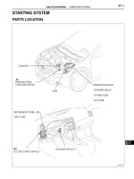
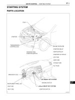
Front Propeller Shaft
Rear Propeller Shaft
80 (820, 59)
106 (1,080, 78)
80 (820, 59)
80 (820, 59)
80 (820, 59)
No.2 Engine Under Cover
106 (1,080, 78) 106 (1,080, 78)
106 (1,080, 78)
N·m (kgf·cm, ft·lbf) : Specified torque
Front Differential
Transfer
Transfer
Rear Differential
Rear propeller shaft
Front propeller shaft
PR-2
-PROPELLER SHAFT PROPELLER SHAFT ASSEMBLY
1941A uthor: Date:
2004 LAND CRUISER (RM1071U)
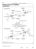
PROPELLER SHAFT ASSEMBLY
COMPONENTS
D03041
Grease Fitting
Propeller Shaft
z Snap Ring
Grease Fitting
z Spider Bearing
Dust Cover
Flange Yoke
Sleeve Yoke
z Spider
Flange Yoke
Front propeller shaft
Rear propeller shaft
z Non-reusable part
z Snap Ring
Grease Fitting
z Spider Bearing
Grease Fitting
z Spider
z Spider
z Spider
Grease Fitting
z Snap Ring
Sleeve Yoke
Flange Yoke
Dust Cover
z Spider Bearing
Propeller Shaft
Flange Yoke
z Snap Ring
z Spider Bearing
Grease Fitting
z
z
-PROPELLER SHAFT PROPELLER SHAFT ASSEMBLY
PR-3
1942A uthor: Date:
2004 LAND CRUISER (RM1071U)
PR03K-02
PR0310
R04447
-PROPELLER SHAFT PROPELLER SHAFT ASSEMBLY
PR-5
1944A uthor: Date:
2004 LAND CRUISER (RM1071U)
INSPECTION
NOTICE:
Be careful not to grip the propeller shaft tube too tightly in
a vise as this will cause deformation.
1. INSPECT FRONT AND REAR PROPELLER SHAFTS
FOR DAMAGE OR RUNOUT
Using a dial indicator, check the runout of shafts.
Maximum runout: 0.8 mm (0.031 in.)
If shaft runout is greater than maximum, replace the shaft.
2. INSPECT SPIDER BEARING
(a) Check the spider bearings for wear or damage.
(b) Check the spider bearing axial play by turning the yoke
with holding the shaft tightly.
Maximum bearing axial play: 0 mm (0 in.)
If necessary, replace the spider bearing.
PR03M-02
-PROPELLER SHAFT PROPELLER SHAFT ASSEMBLY
PR-7
1946A uthor: Date:
2004 LAND CRUISER (RM1071U)
INSTALLATION
Installation is in the reverse order of removal (See page PR-4 ).
HINT:
After installation, pump MP grease into each fitting with a grease gun until the grease begins to flow around
the oil seal.
PR03J-02
Z09285
Front Propeller Shaft
Matchmarks
Transfer
D03068
Rear Propeller Shaft
Matchmarks
Transfer
PR-4
-PROPELLER SHAFT PROPELLER SHAFT ASSEMBLY
1943A uthor: Date:
2004 LAND CRUISER (RM1071U)
REMOVAL
1. REMOVE ENGINE NO. 2 UNDER COVER
2. REMOVE FRONT PROPELLER SHAFT
(a) Place matchmarks on the propeller shaft flange and
transfer.
(b) Remove the 4 nuts and washers.
Torque: 80 N·m (820 kgf·cm, 59 ft·lbf)
(c) Place matchmarks on the propeller shaft flange and front
differential.
(d) Remove the 4 nuts, bolts and washers.
Torque: 80 N·m (820 kgf·cm, 59 ft·lbf)
(e) Remove the front propeller shaft.
3. REMOVE REAR PROPELLER SHAFT
(a) Place matchmarks on the propeller shaft flange and
transfer.
(b) Remove the 4 nuts and washers.
Torque: 106 N·m (1,080 kgf·cm, 78 ft·lbf)
(c) Place matchmarks on the propeller shaft flange and rear
differential.
(d) Remove the 4 nuts, bolts and washers.
Torque: 106 N·m (1,080 kgf·cm, 78 ft·lbf)
(e) Remove the rear propeller shaft.
PR03L-02
D04310
Matchmarks
D03048
1.2 mm
(0.047 in.)
19.5 mm
(0.768 in.)
D03049
A
SST
PR-6
-PROPELLER SHAFT PROPELLER SHAFT ASSEMBLY
1945A uthor: Date:
2004 LAND CRUISER (RM1071U)
REPLACEMENT
NOTICE:
Be careful not to grip the propeller shaft tube too tightly in
a vise as this will cause deformation.
REPLACE DUST COVER
(a) Remove the sleeve yoke from the propeller shaft.
(1) Place matchmarks on the sleeve yoke and shaft.
(2) Pull out the sleeve yoke from the shaft.
(b) Remove the dust cover.
Cut the dust cover spirally at the pressing-in part with a
saw and pry it off with a chisel and hammer.
NOTICE:
Do not damage the propeller shaft. If damaged, replace the
shaft with a new one.
(c) Install a new dust cover.
Using SST and press, press in a new dust cover.
SST 09636-20010
NOTICE:
Place the universal joint straight when pressing in the dust
cover. Apply MP grease to the ’’A’’ part.
(d) Insert the sleeve yoke into the propeller shaft.
(1) Apply MP grease to the propeller shaft spline and
sleeve yoke sliding surface.
(2) Align the matchmarks on the sleeve yoke and pro-
peller shaft.
(3) Install the propeller shaft into the sleeve yoke.
PR04M-01
PR0058
Matchmarks
Z00753
PR0060
SST
A
PR0061
PR-8
-PROPELLER SHAFT SPIDER BEARING
1947Author: Date:
2004 LAND CRUISER (RM1071U)
SPIDER BEARING
REPLACEMENT
NOTICE:
Be careful not to grip the propeller shaft tube too tightly in
a vise as this will cause deformation.
1. REMOVE PROPELLER SHAFT (See page PR-4 )
2. PLACE MATCHMARKS ON SHAFT AND FLANGE
YOKE OR FLANGE YOKE AND SLEEVE YOKE
3. REMOVE SLEEVE YOKE FROM PROPELLER SHAFT
4. REMOVE SNAP RINGS
(a) Using a brass bar and hammer, slightly tap in the bearing
outer races.
(b) Using 2 screwdrivers, remove the 4 snap rings from the
grooves.
5. REMOVE SPIDER BEARINGS
(a) Using SST, push out the bearing from the flange.
SST 09332-25010
HINT:
Sufficiently raise the part indicated by ’’A’’ so that it does not
come into contact with the bearing.
(b) Clamp the bearing outer race in a vise and tap off the
flange with a hammer.
HINT:
Remove the bearing on the opposite side in the same proce-
dure.
(c) Remove the flange yoke from the sleeve yoke (or propel-
ler shaft).
Z00754
SST
Z04247
Yoke
Drill mark
Color
Bearing
Cup
Drill mark
Z00755
PR0081
SST
Q07338
-PROPELLER SHAFT SPIDER BEARING
PR-9
1948Author: Date:
2004 LAND CRUISER (RM1071U)
(d) Install the 2 removed bearing outer races to the spider.
(e) Using SST, push out the bearing from the yoke.
SST 09332-25010
(f) Clamp the outer bearing race in a vise and tap off the yoke
with a hammer.
HINT:
Remove the bearing on the opposite side in the same proce-
dure.
6. SELECT SPIDER BEARING
Select the bearing according to whether or not there is a drill
mark on the yoke section.
Yoke Bearing
w/ drill mark w/ color mark (Red)
No drill mark No color mark
7. INSTALL SPIDER BEARING
(a) Apply MP grease to a new spider and bearings.
NOTICE:
Be careful not to apply too much grease.
(b) Fit the spider into the yoke.
(c) Using SST, install the bearings on the spider.
SST 09332-25010
(d) Using SST, adjust both bearings so that the snap ring
grooves are at maximum and equal in width.
PR0069
M00056
Thickness of snap ring:
Color
Thickness mm (in.)
Brown
Blue
2.44 - 2.46 mm
(0.0961 - 0.0969 in.)
2.46 - 2.48 mm
(0.0969 - 0.0976 in.)
2.30 - 2.32 mm
(0.0906 - 0.0913 in.)
2.34 - 2.36 mm
(0.0921 - 0.0929 in.)
2.28 - 2.30 mm
(0.0898 - 0.0906 in.)
2.32 - 2.34 mm
(0.0913 - 0.0921 in.)
2.36 - 2.38 mm
(0.0929 - 0.0937 in.)
2.38 - 2.40 mm
(0.0937 - 0.0945 in.)
2.40 - 2.42 mm
(0.0945 - 0.0953 in.)
2.42 - 2.44 mm
(0.0953 - 0.0961 in.)
Mark
PR-10
-PROPELLER SHAFT SPIDER BEARING
1949Author: Date:
2004 LAND CRUISER (RM1071U)
8. INSTALL SNAP RING
(a) Install 2 new snap rings of equal thickness which will allow
0 mm (0 in.) axial play.
HINT:
Do not reuse the snap rings.
(b) Using a hammer, tap the yoke until there is no clearance
between the bearing outer race and snap ring.
9. INSTALL FLANGE YOKE TO SLEEVE YOKE (OR PRO-
PELLER SHAFT)
(a) Align the matchmarks on the propeller shaft and flange
yoke or flange yoke and sleeve yoke.
(b) Install the flange yoke to the sleeve yoke (or propeller
shaft).
HINT:
Install 2 new spider bearings and snap ring on the flange yoke
side in the procedure described above.
R04447
D01633
SPIDER GREASE FITTING ASSEMBLY DIRECTION
Front propeller shaft
Rear propeller shaft
The figure at left shows the locations
of the grease fittings as seen from the
rear.
No. 1
Sleeve Yoke
No. 2
No. 1
No. 2
Sleeve Yoke
No. 2
No. 1
Sleeve Yoke
-PROPELLER SHAFT SPIDER BEARING
PR-1 1
1950Author: Date:
2004 LAND CRUISER (RM1071U)
10. CHECK SPIDER BEARING (See page PR-5 )
(a) Check that the spider bearing moves smoothly.
(b) Check the spider bearing axial play.
Maximum bearing axial play: 0 mm (0 in.)
HINT:
When replacing the spider bearing, be sure that the grease fit-
ting assembly hole is facing to the direction shown in the illustra-
tion.
PR03H-02
-PROPELLER SHAFT TROUBLESHOOTING
PR-1
1940Author: Date:
2004 LAND CRUISER (RM1071U)
TROUBLESHOOTING
PROBLEM SYMPTOMS TABLE
Use the table below to help you find the cause of the problem. The numbers indicate the priority of the likely
cause of the problem. Check each part in order. If necessary, replace these parts.
Symptoms Suspect Area See page
Noise
1. Sleeve yoke spline (Worn)
2. Spider bearing (Worn or stuck)
PR-5
PR-5
Vibration
1. Sleeve yoke spline (Stuck)
2. Propeller shaft (Runout)
3. Propeller shaft (Imbalance)
PR-5
PR-5
-