Toyota land cruiser 1998 2007 starting hệ thống khởi động trên xe land cruiser đời 1998 2007
Bạn đang xem bản rút gọn của tài liệu. Xem và tải ngay bản đầy đủ của tài liệu tại đây (461.27 KB, 19 trang )
B16462
ACC Cut Relay
ST0OU-01
S04972
Ohmmeter
Continuity
No continuity
Continuity
Ohmmeter
3
1
4
2
5
S04971
Continuity
No continuity
Ohmmeter
Ohmmeter
Battery
1
2
5
3
4
-STARTING ACC CUT RELAY
ST-19
1835Author: Date:
2004 LAND CRUISER (RM1071U)
ACC CUT RELAY
INSPECTION
1. REMOVE ACC CUT RELAY
Remove the relay box and ACC cut relay.
2. INSPECT ACC CUT RELAY CONTINUITY
(a) Using an ohmmeter, check that there is continuity be-
tween terminals 1 and 2.
If there is no continuity, replace the relay.
(b) Check that there is no continuity between terminals 3 and
5.
If there is continuity, replace the relay.
(c) Check that there is continuity between terminals 3 and 4.
If there is no continuity, replace the relay.
3. INSPECT ACC CUT RELAY OPERATION
(a) Apply battery positive voltage across terminals 1 and 2.
(b) Using an ohmmeter, check that there is no continuity be-
tween terminals 3 and 4.
If there is continuity, replace the relay.
(c) Using an ohmmeter, check that there is continuity be-
tween terminals 3 and 5.
If there is no continuity, replace the relay.
4. REINSTALL ACC CUT RELAY
ST08B-03
B16434
Intake Air Connector
V-Bank Cover
PS Air Hose
EVAP Hose
Air Hose
Fuel Return Hose
PCV Hose
ST-2
-STARTING STARTER
1818Author: Date:
2004 LAND CRUISER (RM1071U)
STARTER
COMPONENTS
B16458
EVAP Pipe
EVAP Hose
Rear Water
Bypass Joint
Injector Connector
VSV Connector
for EVAP
EVAP Hose
Starter Connector
V-Bank
Cover Bracket
Starter
Intake Manifold Assembly
PS Air Hose
Engine Wire
EVAP Hose
S Gasket
S Gasket
S Non-reusable part
39 (400, 29)
Engine Wire
Ignition Coil with
Igniter Connector
Water Bypass Hose
Engine Wire
Engine Wire Protector
Fuel Return Hose
Engine Wire Protector
Engine Wire
V-Bank Cover Bracket
V-Bank
Cover Bracket
V-Bank
Cover Bracket
-STARTING STARTER
ST-3
1819Author: Date:
2004 LAND CRUISER (RM1071U)
B04547
S O-Ring
Idler Gear
Starter Housing
Assembly
Return Spring
Starter Clutch
Assembly
O-Ring
Steel Ball
Contact Plate
S Rear Bearing
Armature
Magnetic Switch
Assembly
Bearing
S Front Bearing
S O-Ring
End Cover
Brush Holder
Field Frame (Field Coil)
Terminal Insulator
Magnetic Switch Assembly
Wave Washer
Terminal Nut
O-Ring
Terminal Insulator
Terminal Bolt
S Terminal C Kit Part
Lead Terminal
Plunger
S Gasket
End Cover
Terminal Insulator
Terminal Bolt
Contact Plate
Terminal Insulator
Wave Washer
O-Ring
Terminal Nut
S Terminal 30 Kit Part
S Non-reusable part
Packing
S Dust Protector
S Dust Protector
S O-Ring
ST-4
-STARTING STARTER
1820Author: Date:
2004 LAND CRUISER (RM1071U)
ST08D-04
B04550
Dust Protector
B04632
B04551
B04552
(2)
(3)
(1)
(4)
(5)
ST0948
Magnetic Finger
ST-6
-STARTING STARTER
1822Author: Date:
2004 LAND CRUISER (RM1071U)
DISASSEMBLY
1. REMOVE 2 DUST PROTECTORS
2. REMOVE FIELD FRAME AND ARMATURE
(a) Remove the nut, and disconnect the lead wire from the
magnetic switch terminal.
Torque: 5.9 N·m (60 kgf·cm, 52 in.·lbf)
(b) Remove the 2 through bolts.
Torque: 9.3 N·m (95 kgf·cm, 82 in.·lbf)
(c) Pull out the field frame together with the armature from the
magnetic switch assembly.
NOTICE:
At the time of notice, align the protrusion of the field frame
with the groove of the magnetic switch.
(d) Remove the O-ring from the field frame.
HINT:
At the time of assembly, use a new O-ring.
3. REMOVE STARTER HOUSING, CLUTCH ASSEMBLY
AND GEAR
(a) Remove the 2 screws.
Torque: 9.3 N·m (95 kgf·cm, 82 in.·lbf)
(b) Remove these parts from the magnetic switch assembly:
(1) Starter housing
(2) Return spring
(3) Idler gear
(4) Bearing
(5) Starter clutch assembly
HINT:
At the time of assembly, apply grease to the return spring and
insert the return spring into the clutch shaft hole.
4. REMOVE STEEL BALL
Using a magnetic finger, remove the steel ball from the clutch
shaft hole.
HINT:
At the time of assembly, apply grease to the steel ball and insert
the steel ball into the clutch shaft hole.
B04654
P10568
-STARTING STARTER
ST-7
1823Author: Date:
2004 LAND CRUISER (RM1071U)
5. REMOVE BRUSH HOLDER
(a) Remove the 2 screws w/ O-ring and the end cover from
the field frame.
Torque: 3.8 N·m (39 kgf·cm, 34 in.·lbf)
(b) Remove the O-ring from the field frame.
HINT:
At the time of assembly, use a new O-ring.
(c) Using a screwdriver, hold the spring back and disconnect
the brush from the brush holder. Disconnect the 4
brushes, and remove the brush holder.
NOTICE:
Check that the positive (+) lead wires are not grounded.
6. REMOVE ARMATURE FROM FIELD FRAME
ST08E-03
S00054
Ohmmeter
Continuity
S00055
Ohmmeter No Continuity
S00056
S00057
ST0040
ST-8
-STARTING STARTER
1824Author: Date:
2004 LAND CRUISER (RM1071U)
INSPECTION
1. INSPECT COMMUTATOR FOR OPEN CIRCUIT
Using an ohmmeter, check that there is continuity between the
segments of the commutator.
If there is no continuity between any segment, replace the ar-
mature.
2. INSPECT COMMUTATOR FOR GROUND
Using an ohmmeter, check that there is no continuity between
the commutator and armature coil core.
If there is continuity, replace the armature.
3. INSPECT COMMUTATOR FOR DIRTY AND BURNT
SURFACE
If the surface is dirty or burnt, correct it with sandpaper (No.400)
or on a lathe.
4. INSPECT COMMUTATOR CIRCLE RUNOUT
(a) Place the commutator on V-blocks.
(b) Using a dial indicator the circle runout.
Maximum circle runout:
0.05 mm (0.0020 in.)
If the circle runout is greater than maximum, correct it on a lathe.
5. INSPECT COMMUTATOR DIAMETER
Using vernier calipers, measure the commutator diameter.
Standard diameter:
35.0 mm (1.378 in.)
Minimum diameter:
34.0 mm (1.339 in.)
If the diameter is less than minimum, replace the armature.
6. INSPECT UNDERCUT DEPTH
Check that the undercut depth is clean and free of foreign mate-
rials. Smooth out the edge.
Standard undercut depth:
0.7 mm (0.028 in.)
Minimum undercut depth:
0.2 mm (0.008 in.)
If the undercut depth is less than minimum, correct it with a
hacksaw blade.
P10588
Ohmmeter
Continuity
S02267
Ohmmeter
(A)
(B)
Z00037
ST0019
P21088
Ohmmeter
No Continuity
-STARTING STARTER
ST-9
1825Author: Date:
2004 LAND CRUISER (RM1071U)
7. INSPECT FIELD COIL FOR OPEN CIRCUIT
Using an ohmmeter, check that there is continuity between the
lead wire and field coil brush lead.
If there is no continuity, replace the field frame.
8. INSPECT SHUNT COIL FOR OPEN CIRCUIT
Using an ohmmeter, measure the resistance between shunt
coil terminals (A) and (B).
Resistance:
1.5 - 1.9 Ω at 20°C (68°F)
If the resistance is not as specified, replace the field frame.
9. INSPECT BRUSH LENGTH
Using vernier calipers, measure the brush length.
Standard length:
15.0 mm (0.591 in.)
Minimum length:
9.0 mm (0.354 in.)
If the length is less than minimum, replace the brush holder and
field frame.
10. INSPECT BRUSH SPRING LOAD
Using a pull scale, measure the spring load by pulling the spring
from the brush until they are separated.
Standard spring installed load:
21.5 - 27.5 N (2.2 - 2.8 kgf, 4.8 - 6.2 lbf)
Minimum spring installed load:
12.7 N (1.3 kgf, 2.9 lbf)
If the installed load is less than minimum, replace the brush
springs.
11. INSPECT BRUSH HOLDER INSULATION
Using an ohmmeter, check that there is no continuity between
the positive (+) and negative (-) brush holders.
If there is continuity, repair or replace the brush holder.
12. INSPECT GEAR TEETH
Check the gear teeth on the pinion gear, idle gear and the clutch
assembly for wear or damage.
If any damage is found, replace the gear or clutch assembly,
and also check the drive plate ring gear for wear or damage.
P10821
Free
Lock
B04553
Terminal C
Terminal 50
Continuity
Ohmmeter
B04554
Continuity Ohmmeter
Terminal 50
ST-10
-STARTING STARTER
1826Author: Date:
2004 LAND CRUISER (RM1071U)
13. INSPECT CLUTCH PINION GEAR
Rotate the pinion gear clockwise, and check that it turns freely.
Check that it locks by rotating the pinion gear counterclockwise.
If necessary, replace the clutch assembly.
14. DO PULL-IN COIL OPEN CIRCUIT TEST
Using an ohmmeter, check that there is continuity between ter-
minals 50 and C.
If there is no continuity, replace the magnetic switch.
15. DO HOLD-IN COIL OPEN CIRCUIT TEST
Using an ohmmeter, check that there is continuity between ter-
minal 50 and the switch body.
If there is no continuity, replace the magnetic switch.
ST08I-04
B04549
Starter
Connector
Engine Wire Protector
B04548
-STARTING STARTER
ST-17
1833Author: Date:
2004 LAND CRUISER (RM1071U)
INSTALLATION
1. INSTALL STARTER
(a) Install the engine wire protector to the starter with the bolt.
Torque: 9.81 N·m (100 kgf·cm, 84 in.·lbf)
(b) Connect the starter wire with the nut.
Torque: 9.81 N·m (100 kgf·cm, 84 in.·lbf)
(c) Connect the starter connector.
(d) Connect the starter to the cylinder block.
(e) Connect the engine wire with the bolt.
(f) Install the starter with the 2 bolts.
Torque: 39 N·m (400 kgf·cm, 29 ft·lbf)
2. INSTALL INTAKE MANIFOLD ASSEMBLY
(See page EM-59 )
3. INSTALL INTAKE AIR CONNECTOR
4. INSTALL V-BANK COVER
ST08G-06
-STARTING STARTER
ST-15
1831Author: Date:
2004 LAND CRUISER (RM1071U)
REASSEMBLY
Reassembly is in the reverse order of disassembly (See page ST-6 ).
HINT:
At the time of assembly, use high-temperature grease to lubricate the bearing and gears when assembling
the starter.
ST08C-04
B04548
B04549
Starter
Connector
Engine Wire Protector
-STARTING STARTER
ST-5
1821Author: Date:
2004 LAND CRUISER (RM1071U)
REMOVAL
1. REMOVE V-BANK COVER
2. REMOVE INTAKE AIR CONNECTOR
3. REMOVE INTAKE MANIFOLD ASSEMBLY
(See page EM-35 )
4. REMOVE STARTER
(a) Remove the 2 bolts holding the starter from the cylinder
block.
(b) Disconnect the starter from the cylinder block.
(c) Disconnect the starter connector.
(d) Remove the nut, bolt and disconnect the starter wire.
(e) Remove the bolt, and disconnect the engine wire protec-
tor from the starter.
(f) Remove the starter.
ST08F-07
S00058
SST
S00059
S00060
SST
S00061
SST
Upward
Downward
B04542
-STARTING STARTER
ST-1 1
1827Author: Date:
2004 LAND CRUISER (RM1071U)
REPLACEMENT
1. REPLACE REAR BEARING
(a) Using SST, remove the bearing.
SST 09286-4601 1
(b) Using a press, press in a new bearing.
2. REPLACE FRONT BEARING
(a) Using SST, remove the bearing.
SST 09286-4601 1
(b) Using SST and a press, press in a new bearing.
NOTICE:
Be careful of the bearing installation direction.
SST 09820-00031
3. REPLACE MAGNETIC SWITCH TERMINAL KIT
PARTS
(a) Remove the magnetic switch end cover.
Remove the 3 bolts, the end cover, the gasket and the
plunger.
B04555
Wear
B04556
SST
B04557
(2)
(1)
(4)
(3)
(7)
(5)
(6)
Long
Short
Inside
ST-12
-STARTING STARTER
1828Author: Date:
2004 LAND CRUISER (RM1071U)
(b) Inspect contact plate for wear.
Using vernier calipers, measure the contact plate for
depth of wear.
Maximum wear:
0.9 mm (0.035 in.)
If the depth of wear is greater than the maximum, replace the
contact plate.
(c) Remove terminal kit parts.
(1) Using SST, loosen the terminal nuts.
SST 09810-38140
(2) Terminal C:
Remove the terminal nut, wave washer, terminal in-
sulator (outside), O- ring, terminal bolt, contact
plate and terminal insulator (inside).
(3) Terminal 30:
Remove the terminal nut, wave washer, terminal in-
sulator (outside), O- ring, terminal bolt, contact
plate, terminal insulator (inside).
(d) Temporarily install these new terminal 30 kit parts:
(1) Terminal insulator (inside)
(2) Contact plate
(3) Terminal bolt
(4) O-ring
(5) Packing and terminal insulator (outside)
Install the packing to the terminal insulator, and
install them.
HINT:
Match the protrusion of the insulator with the indentation of the
housing.
(6) Wave washer
(7) Terminal nut
NOTICE:
Be careful to install the terminal insulator (inside) and wave
washer in the correct direction.
B04559
(1)
Long
(2)
(3)
(4)
(5)
(6)
(7)
Short
Inside
Lead Terminal
B04560
40 mm
37 mm
20 mm
Contact
Plate
(kgf/cm
2
)
(psi)
(kPa) = (psi) x 6.9
100 kgf
2
Ram diameter (cm)
(kPa) = (kgf/cm
2
) x 98.1
=
=
x 3.14 (π)
2
221lbf
2
Ram diameter (in.)
x 3.14 (π)
2
-STARTING STARTER
ST-13
1829Author: Date:
2004 LAND CRUISER (RM1071U)
(e) Temporarily install these new terminal C kit parts:
(1) Terminal insulator (inside)
(2) Contact plate
(3) Terminal bolt
(4) O-ring
(5) Terminal insulator (outside)
(6) Wave washer
(7) Terminal nut
NOTICE:
Be careful to install the terminal insulator (inside) and wave
washer in the correct direction.
(f) Temporarily tighten the terminal nuts.
(g) Tighten terminal nuts.
(1) Put a wooden block on the contact plate and press
it down with a hand press.
Dimensions of wooden block:
20 x 37 x 40 mm (0.79 x 1.46 x 1.57 in.)
Press force:
981 N (100 kgf, 221 lbf)
NOTICE:
S Check the diameter of the hand press ram. Then cal-
culate the gauge pressure of the press when
981 N (100 kgf, 221 lbf) of force is applied.
Gauge pressure:
S If the contact plate is not pressed down with the spe-
cified pressure, the contact plate may tilt due to coil
deformation or the tightening of the nut.
B04561
SST
B04562
ST-14
-STARTING STARTER
1830Author: Date:
2004 LAND CRUISER (RM1071U)
(2) Using SST, tighten the nuts to the specified torque.
SST 09810-38140
Torque: 17 N·m (170 kgf·cm, 13 ft·lbf)
NOTICE:
If the nut is over tightened, it may cause cracks on the in-
side of the insulator.
(h) Clean contact surfaces of the contact plate and the plung-
er.
Clean the contact surfaces of the remaining contact plate
and plunger with a dry shop rag.
(i) Reinstall the magnetic switch end cover.
Install the plunger, the new gasket, the end cover and
lead clamp with the 3 bolts.
Torque: 3.6 N·m (37 kgf·cm, 32 in.·lbf)
ST08H-07
B04543
Terminal 50
Battery
Terminal C
B04544
Battery
Terminal C
Disconnect
B04545
Disconnect
Battery
B04546
Terminal 30
Battery
Ammeter
Terminal 50
ST-16
-STARTING STARTER
1832Author: Date:
2004 LAND CRUISER (RM1071U)
TEST
NOTICE:
These tests must be done within 3 to 5 seconds to avoid the
coil to be burned-out.
1. DO PULL-IN TEST
(a) Disconnect the field coil lead wire from terminal C.
(b) Connect the battery to the magnetic switch as shown.
Check that the pinion gear moves outward.
2. DO HOLD-IN TEST
While connected as above with the pinion gear out, disconnect
the negative (-) lead from terminal C. Check that the pinion gear
remains out.
3. INSPECT CLUTCH PINION GEAR RETURN
Disconnect the negative (-) lead from the starter body. Check
that the pinion gear returns inward.
4. DO NO-LOAD PERFORMANCE TEST
(a) Connect the battery and ammeter to the starter as shown.
(b) Check that the starter rotates smoothly and steadily with
the pinion gear moving out. Check that the ammeter
shows the specified current.
Specified current:
At 11.5 V: 100 A or less
B16459
Starter
Relay
ST08J-07
B05486
1
Ohmmeter
Ohmmeter
2
3
5
Continuity
No Continuity
B05487
1
Ohmmeter
Continuity
2
3
5
Battery
ST-18
-STARTING STARTER RELAY
1834Author: Date:
2004 LAND CRUISER (RM1071U)
STARTER RELAY
INSPECTION
1. REMOVE STARTER RELAY (Marking: ”ST”)
Remove the relay box cover and starter relay.
2. INSPECT RELAY CONTINUITY
(a) Using an ohmmeter, check that there is continuity be-
tween terminals 1 and 2.
If there is no continuity, replace the relay.
(b) Check that there is no continuity between terminals 3 and
5.
If there is continuity, replace the relay.
3. INSPECT RELAY OPERATION
(a) Apply battery voltage across terminals 1 and 2.
(b) Using an ohmmeter, check that there is continuity be-
tween terminals 3 and 5.
If there is no continuity, replace the relay.
4. REINSTALL STARTER RELAY
ST08A-01
-STARTING STARTING SYSTEM
ST-1
1817Author: Date:
2004 LAND CRUISER (RM1071U)
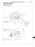
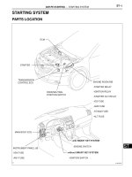
STARTING SYSTEM
ON-VEHICLE INSPECTION
NOTICE:
Before changing the starter, check these items again:
S Connector connection
S Accessory installation, e.g.: theft deterrent system