toyota rav4 1994-2000 ignition system - hệ thống đánh lửa trên xe rav4 đời 1994-2000
Bạn đang xem bản rút gọn của tài liệu. Xem và tải ngay bản đầy đủ của tài liệu tại đây (374.2 KB, 16 trang )
IG0J3−02
−IGNITION IGNITION SYSTEM
IG−1
1996 RAV4 (RM447U)
IGNITION SYSTEM
ON−VEHICLE INSPECTION
NOTICE:
”Cold” and ”Hot” in these sentences express the tempera-
ture of the coils themselves. ”Cold” is from −10°C (14°F) to
50°C (122°F) and ”Hot” is from 50°C (122°F) to 100°C
(212°F).
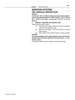
1. INSPECT IGNITERS AND SPARK TEST
Check that the spark occurs.
(1) Disconnect the high−tension cord (from the ignition
coil) from the distributor cap.
(2) Hold the end approx. 12.5 mm (0.50 in.) from the
body ground.
(3) See if spark occurs while engine is being cranked.
NOTICE:
To prevent gasoline from being injected from injectors dur-
ing this test, crank the engine for no more than 5 − 10 se-
conds at time.
If the spark does not occur, perform the test as follows:
SPARK TEST
CHECK CONNECTION OF IGNITION COIL, IGNITER
AND DISTRIBUTOR CONNECTORS.
CHECK RESISTANCE OF HIGH−TENSION CORDS
TRY ANOTHER IGNITER
Maximum resistance: 25 kΩ per cord
(See step 2)
CHECK POWER SUPPLY TO IGNITION COIL AND
IGNITER
1. Turn ignition switch to ON.
2. Check that there is battery positive voltage at ignition coil
positive (+) terminal.
Check wiring between ECM, distributor
and igniter, and then try another ECM.
CHECK IGT SIGNAL FROM ECM
NO
BAD
OK
OK
OK
Connect securely.
Replace the cord(s).
Check wiring between ignition switch
to ignition coil and igniter.
BAD
BAD
BAD
(See page DI−100)
Cold Hot
0.36 − 0.55 Ω 0.45 − 0.65 Ω
CHECK RESISTANCE OF IGNITION COIL
OK
Replace the ignition coil.
BAD
Resistance:
(See step 4)
Primary
Secondary
9.0 − 15.4 kΩ 11.4 − 18.1 kΩ
CHECK RESISTANCE OF SIGNAL GENERATOR
Resistance: Cold Hot
OK
Replace the distributor housing assembly.
(PICKUP COIL)
(See step 5)
135 − 220 Ω 175 − 255 Ω
CHECK RESISTANCE OF CRANKSHAFT POSITION
SENSOR
Resistance: Cold Hot
OK
Replace the crankshaft position sensor.
(See step 6)
985 − 1,600 Ω 1,265 − 1,890 Ω
BAD
BAD
OK
CHECK AIR GAP OF DISTRIBUTOR
Air gap: 0.2 − 0.4 mm (0.008 − 0.016 in.)
Replace the distributor housing assembly.
(See step 5)
BAD
IG−2
−IGNITION IGNITION SYSTEM
1996 RAV4 (RM447U)
B11562
P17875
Ohmmeter
IG0147
Megger
Ground
N00917
−IGNITION IGNITION SYSTEM
IG−3
1996 RAV4 (RM447U)
2. INSPECT HIGH−TENSION CORDS
(a) Disconnect the high−tension cords from spark plug.
Disconnect the high−tension cords at the rubber boot. Do
not pull on the high−tension cords.
NOTICE:
Pulling on or bending the cords may damage the conductor
inside.
(b) Disconnect the high−tension cords from ignition coil.
(c) Disconnect the high−tension cords from distributor cap.
(d) Inspect the high−tension cord resistance.
Using an ohmmeter, measure the resistance.
Maximum resistance: 25 kΩ per cord
If the resistance is greater than maximum, check the terminals.
If necessary, replace the high−tension cord.
(e) Reconnect the high−tension cords to distributor cap.
(f) Reconnect the high−tension cord to ignition coil.
(g) Reconnect the high−tension cords to spark plugs.
3. INSPECT SPARK PLUGS
NOTICE:
S Never use a wire brush for cleaning.
S Never attempt to adjust the electrode gap on a used
spark plug.
S Spark plugs should be replaced every 100,000 km
(60,000 miles).
(a) Disconnect the high−tension cords from the spark plugs.
(b) Using a megger (insulation resistance meter), measure
the insulation resistance.
Standard correct insulation resistance:
10 MΩ or more
If the resistance is less than specified, proceed to step (d).
HINT:
If a megger is not available, the following simple method of in-
spection provides fairly accurate results.
Simple Method:
S Quickly race the engine to 4,000 rpm 5 times.
S Remove the spark plug. (See step (c))
S Visually check the spark plug.
If the electrode is dry OK
If the electrode is wet Proceed to step (d)
S Reinstall the spark plug. (See step (g))
S05308
16mm Plug
Wrench
Z00032
IG0152
IG−4
−IGNITION IGNITION SYSTEM
1996 RAV4 (RM447U)
(c) Using a 16 mm plug wrench, remove the 4 spark plugs.
(d) Visually check the spark plug for thread damage and insu-
lator damage.
If abnormal, replace the spark plug.
Recommended spark plug:
DENSO PK20R11
NGK BKR6EP−11
(e) Inspect the electrode gaps.
Maximum electrode gap for used spark plug:
1.3 mm (0.051 in.)
If the gap is greater than maximum, replace the spark plug.
Correct electrode gap for new spark plug:
1.1 mm (0.043 in.)
NOTICE:
If adjusting the gap of a new spark plug, bend only the base
of the ground electrode. Do not touch the tip. Never attempt
to adjust the gap on the used plug.
(f) Clean the spark plugs.
If the electrode has traces of wet carbon, allow it to dry and then
clean with a spark plug cleaner.
Air pressure: Below 588 kPa (6 kgf/cm
2
, 85 psi)
Duration: 20 seconds or less
HINT:
If there are traces of oil, remove it with gasoline before using the
spark plug cleaner.
(g) Using a 16 mm plug wrench, install the 4 spark plugs.
Torque: 18 N·m (180 kgf·cm, 13 ft·lbf)
(h) Reconnect the high−tension cords from the spark plugs.
4. INSPECT IGNITION COILS
(a) Disconnect the ignition coil connector.
(b) Disconnect the high−tension cord from ignition coil.
(c) Inspect the primary coil resistance.
Using an ohmmeter, measure the resistance between the
positive (+) and negative (−) terminals.
Primary coil resistance:
Cold 0.36 − 0.55 Ω
Hot 0.45 − 0.65 Ω
If the resistance is not as specified, replace the ignition coil.
B11565
B11566
B11567
−IGNITION IGNITION SYSTEM
IG−5
1996 RAV4 (RM447U)
(d) Inspect the secondary coil resistance.
Using an ohmmeter, measure the resistance between the
positive (+) and high−tension terminals.
Secondary coil resistance:
Cold 9.0 − 15.4 kΩ
Hot 11.4 − 18.1 kΩ
If the resistance is not as specified, replace the ignition coil.
(e) Reconnect the high−tension cord to ignition coil.
(f) Reconnect the ignition coil connector.
5. INSPECT DISTRIBUTOR
(a) Remove the distributor cap.
Remove the 2 bolts, and disconnect the distributor cap
from the distributor housing.
(b) Remove the rotor.
(c) Inspect the air gap.
Using SST, measure the air gap between the signal rotor
and pick up coil projection.
SST 09240−00020
Air gap: 0.2 − 0.45 mm (0.008 − 0.018 in.)
If the air gap is not as specified, replace the distributor housing
assembly.
(d) Disconnect the distributor connector.
(e) Inspect the signal generator (Pickup coil) resistance.
Using an ohmmeter, measure the resistance between ter-
minals.
Pickup coil resistance:
Cold 135 − 220 Ω
Hot 175 − 255 Ω
If the resistance is not as specified, replace the distributor hous-
ing assembly.
(f) Reconnect the distributor connector.
(g) Reinstall the rotor.
(h) Reinstall the distributor cap.
Install a new packing and distributor cap with the 2 bolts.
B11568
B11569
IG−6
−IGNITION IGNITION SYSTEM
1996 RAV4 (RM447U)
6. INSPECT CRANKSHAFT POSITION SENSOR
(a) Disconnect the crankshaft position sensor connector
from generator drive belt adjusting bar.
(b) Inspect the crankshaft position sensor resistance.
Using an ohmmeter, measure the resistance between ter-
minals.
Resistance:
Cold 985 − 1,600 Ω
Hot 1,265 − 1,890 Ω
If the resistance is not as specified, replace the crankshaft posi-
tion sensor.
(c) Reconnect the crankshaft position sensor connector.
IG0J4−01
B11570
−IGNITION DISTRIBUTOR
IG−7
1996 RAV4 (RM447U)
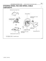
DISTRIBUTOR
COMPONENTS
P23848
Non−reusable part
Packing
Distributor Housing Assembly
Rotor
z
z
Distributor Cap
IG−8
−IGNITION DISTRIBUTOR
1996 RAV4 (RM447U)
IG0J5−02
−IGNITION DISTRIBUTOR
IG−9
1996 RAV4 (RM447U)
REMOVAL
1. REMOVE AIR CLEANER CAP ASSEMBLY (See page ST−4)
2. DISCONNECT DISTRIBUTOR CONNECTOR
3. DISCONNECT HIGH−TENSION CORD FROM IGNITION COIL
4. DISCONNECT HIGH−TENSION CORDS FROM SPARK PLUGS
NOTICE:
Pulling on or bending the cords may damage the conductor inside.
5. REMOVE DISTRIBUTOR
(a) Remove the hold−down bolt, and pull out the distributor.
(b) Remove the O−ring from the distributor housing.
IG0J6−01
IG−10
−IGNITION DISTRIBUTOR
1996 RAV4 (RM447U)
DISASSEMBLY
1. REMOVE DISTRIBUTOR CAP
Remove the 2 bolts, distributor cap and packing.
2. REMOVE ROTOR
Remove the 2 screws and rotor.
IG0J7−01
P23840
−IGNITION DISTRIBUTOR
IG−11
1996 RAV4 (RM447U)
INSPECTION
INSPECT SHAFT
Turn the shaft and check that is not rough or worn
If it feels rough or worn, replace the distributor housing assem-
bly.
IG0J8−01
P23836
B11572
IG−12
−IGNITION DISTRIBUTOR
1996 RAV4 (RM447U)
REASSEMBLY
1. INSTALL ROTOR
(a) Align the hollow of the signal rotor with the protrusion of
the rotor.
(b) Install the rotor with the 2 screws.
2. INSTALL DISTRIBUTOR CAP
(a) Install a new packing to the distributor housing.
(b) Install the distributor cap with the 2 bolts.
IG0J9−01
B11573
B11574
−IGNITION DISTRIBUTOR
IG−13
1996 RAV4 (RM447U)
INSTALLATION
1. SET NO. 1 CYLINDER TO DTC/COMPRESSION
Turn the crankshaft clockwise, and position the slit of the intake
camshaft as shown in the illustration.
2. INSTALL DISTRIBUTOR
(a) Install a new O−ring to the housing.
(b) Apply a light coat of engine oil on the O−ring.
(c) Align the cutout of the coupling with the line of the hous-
ing.
(d) Insert the distributor, aligning the center of the flange with
that of bolt hole on the cylinder head.
(e) Tighten the hold−down bolt.
Torque: 19 N·m (195 kgf·cm, 14 ft·lbf)
3. CONNECT HIGH−TENSION CORDS TO SPARK
PLUGS
Firing order:
1 − 3 − 4 − 2
4. CONNECT HIGH−TENSION CORD TO IGNITION COIL
5. CONNECT DISTRIBUTOR CONNECTOR
6. INSTALL AIR CLEANER CAP ASSEMBLY
IG06J−03
IG−14
−IGNITION CRANKSHAFT POSITION SENSOR
1996 RAV4 (RM447U)
CRANKSHAFT POSITION SENSOR
COMPONENTS
IG06K−02
B11571
−IGNITION CRANKSHAFT POSITION SENSOR
IG−15
1996 RAV4 (RM447U)
REMOVAL
1. DISCONNECT CRANKSHAFT POSITION SENSOR
CONNECTOR FROM GENERATOR DRIVE BELT AD-
JUSTING BAR
2. REMOVE NO.1 TIMING BELT COVER
(See page EM−15)
3. REMOVE CRANKSHAFT POSITION SENSOR
Remove the bolt and disconnect the crankshaft position sensor.
IG06M−02
IG−16
−IGNITION CRANKSHAFT POSITION SENSOR
1996 RAV4 (RM447U)
INSTALLATION
1. INSTALL CRANKSHAFT POSITION SENSOR
Install the crankshaft position sensor with the bolt.
Torque: 9.5 N·m (97 kgf·cm, 84 in.·lbf)
2. INSTALL NO.1 TIMING BELT COVER (See page EM−20)
3. CONNECT CRANKSHAFT POSITION SENSOR CONNECTOR TO GENERATOR DRIVE BELT AD-
JUSTING BAR