toyota rav4 1994-2000 propeller shaft - hệ thống truyền lực trên xe toyota rav4 đời 1994 -2000
Bạn đang xem bản rút gọn của tài liệu. Xem và tải ngay bản đầy đủ của tài liệu tại đây (238.82 KB, 9 trang )
PR02P−02
−PROPELLER SHAFT TROUBLESHOOTING
PR−1
1996 RAV4 (RM447U)
TROUBLESHOOTING
PROBLEM SYMPTOMS TABLE
Use the table below to help you find the cause of the problem. The numbers indicate the priority of the likely
cause of the problem. Check each part in order. If necessary, replace these parts.
Symptom Suspect Area See page
Noise
3. Sleeve yoke spline (Worn)
4. Center support bearing (Worn)
5. Spider bearing (Worn or stuck)
PR−6
PR−6
PR−6
Vibration
1. Rear propeller and intermediate shafts (Runout)
2. Propeller shafts (Imbalance)
3. Universal joint flange (Runout)
4. Cross groove joint (Stuck or damaged)
5. Sleeve yoke spline (Stuck)
PR−6
PR−6
PR−6
PR−6
PR−6
PR02Q−01
Q08982
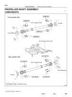
z Dust Cover
Intermediate Shaft
Plate Washer
Center Support Bearing
Plate Washer
Universal Joint Flange
Cross Groove Joint Washer
Propeller Shaft
N·m (kgf·cm, ft·lbf) : Specified torque
z Non−reusable part
x6
27 (275, 20)
74 (750, 54)
z
37 (375, 27)
See page PR−9
PR−2
−PROPELLER SHAFT PROPELLER SHAFT ASSEMBLY
1996 RAV4 (RM447U)
PROPELLER SHAFT ASSEMBLY
COMPONENTS
PR02R−01
F03298
Q08983
Matchmarks
Q05852
Q05853
SST
−PROPELLER SHAFT PROPELLER SHAFT ASSEMBLY
PR−3
1996 RAV4 (RM447U)
REMOVAL
1. LOOSEN CROSS GROOVE JOINT SET BOLT
(a) Depress the brake pedal and hold it.
(b) Using a hexagon wrench, loosen the cross groove joint
set bolts 1/2 turn.
HINT:
Put a piece of cloth, or equivalent, into the inside of the cross
groove joint cover so that the boot does not touch the inside of
the cross groove joint cover.
(c) Loosen the 2 bolts and center support bearing.
2. DISCONNECT PROPELLER SHAFT FROM DIFFER-
ENTIAL
(a) Place matchmarks on both flanges.
(b) Remove the 4 bolts, washers and nuts.
3. REMOVE PROPELLER SHAFT FROM TRANSAXLE
(a) Remove the 2 bolts and center support bearing.
(b) Pull out the propeller shaft yoke from the transaxle.
(c) Insert SST in the transaxle to prevent oil leakage.
SST 09325−20010
Q06266
Matchmarks
PR−4
−PROPELLER SHAFT PROPELLER SHAFT ASSEMBLY
1996 RAV4 (RM447U)
4. SEPARATE INTERMEDIATE SHAFT AND REAR PRO-
PELLER SHAFT
(a) Place matchmarks on the joint and flange.
HINT:
Do not place the matchmarks with a punch.
(b) Using a hexagon wrench, remove the 6 bolts and 3 wash-
ers to separate intermediate propeller shaft and propeller
shaft.
Q06053
PR07P−01
Q05963
Matchmarks
Q06058
SST
Q06082
−PROPELLER SHAFT PROPELLER SHAFT ASSEMBLY
PR−5
1996 RAV4 (RM447U)
DISASSEMBLY
1. REMOVE CENTER SUPPORT BEARING
(a) Using a hammer and chisel, loosen the staked part of the
nut.
(b) Using a vise to hold the front flange, remove the nut and
plate washer.
(c) Place matchmarks on the flange and shaft.
(d) Using SST, remove the universal joint flange.
SST 09950−40010 (09951−04020, 09952−04010,
09953−04030, 09954−04010, 09955−04060,
09958−04010)
(e) Remove the center support bearing and plate washer.
2. INSPECT CENTER SUPPORT BEARING
(a) Turn the bearing by hand with applying force in the rota-
tion direction. Check the bearing turns smoothly.
(b) Check that the seals are not cracked or damaged.
If the bearing is damaged, worn, or does not turn freely, replace
it.
PR07Q−01
Q06054
Q06061
Q06062
Q05792
Q06046
PR−6
−PROPELLER SHAFT PROPELLER SHAFT ASSEMBLY
1996 RAV4 (RM447U)
INSPECTION
1. INSPECT INTERMEDIATE AND REAR PROPELLER
SHAFTS RUNOUT
Using a dial indicator, inspect the intermediate shaft and propel-
ler shaft.
Maximum runout: 0.8 mm (0.031 in.)
If the shaft runout is greater than the maximum, replace the
shaft.
2. INSPECT UNIVERSAL JOINT FLANGE RUNOUT
(a) Using a dial indicator, inspect the rear side of universal
joint flange runout in the horizontal direction.
Maximum runout: 0.1 mm (0.004 in.)
(b) Using a dial indicator, inspect the rear side of universal
joint flange runout in the vertical direction.
Maximum runout: 0.1 mm (0.004 in.)
3. INSPECT SPIDER BEARING
Check the spider bearing axial play by turning the flange with
holding the shaft tightly.
4. INSPECT CROSS GROOVE JOINT
Check that the joint turns smoothly in the directions as shown.
Check for damage or grease leakage from the boot.
If a problem is found, replace the rear propeller shaft.
PR02T−01
Q08048
Q08119
−PROPELLER SHAFT PROPELLER SHAFT ASSEMBLY
PR−7
1996 RAV4 (RM447U)
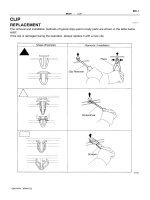
REPLACEMENT
REPLACE DUST COVER
(a) Using a screwdriver and hammer, remove the dust cover.
(b) Using 2 screwdrivers and hammers, install a new dust
cover.
NOTICE:
Be careful not to damage the dust cover.
Q05879
Rear
PR07R−01
Q06110
Matchmarks
PR−8
−PROPELLER SHAFT PROPELLER SHAFT ASSEMBLY
1996 RAV4 (RM447U)
REASSEMBLY
1. INSTALL CENTER SUPPORT BEARING
(a) Set the center support bearing on the intermediate shaft
as shown.
(b) Install the plate washer to the intermediate shaft.
(c) Align the matchmarks on the flange and shaft and place
the flange on the shaft.
(d) Using a vise to hold the flange, press the bearing into
position by tightening down a new nut and washer.
Torque: 181 N·m (1,850 kgf·cm, 134 ft·lbf)
(e) Loosen the nut.
(f) Torque the nut again.
Torque: 69 N·m (700 kgf·cm, 51 ft·lbf)
(g) Using a hammer and chisel, stake the nut.
2. INSTALL JOINT END COVER
(a) Align the matchmarks and install the universal joint flange
to the cross groove joint.
(b) Tighten the 6 bolts and 3 washers to press the joint end
cover.
HINT:
Tighten the bolts gradually and equally to prevent damaging the
end cover.
(c) Remove the 6 bolts and 3 washers and separate the uni-
versal joint flange from the cross groove joint.
3. INSPECT CROSS GROOVE JOINT (See page
PR−6)
4. CONNECT FRONT PROPELLER SHAFT WITH REAR
PROPELLER SHAFT
Using a hexagon wrench, tighten the 6 bolts and 3 washers
temporarily.
HINT:
Put a piece of cloth or an equivalent into the inside of the univer-
sal joint cover.
PR07S−01
Q05756
65.5 − 70.5 mm
(2.579 − 2.776 in.)
Q06145
11.5 − 13.5 mm
(0.453 − 0.536 in.)
−PROPELLER SHAFT PROPELLER SHAFT ASSEMBLY
PR−9
1996 RAV4 (RM447U)
INSTALLATION
1. INSTALL INTERMEDIATE SHAFT
(a) Remove SST from the transfer.
(b) Insert the yoke into the transfer.
2. INSTALL CENTER SUPPORT BEARING TEMPORARI-
LY
3. INSTALL PROPELLER SHAFT
(a) Align the matchmarks on the flanges and connect the
shaft with the 4 bolts, washers and nuts.
(b) Torque the bolts and nuts.
Torque: 74 N·m (750 kgf·cm, 54 ft·lbf)
4. TIGHTEN CROSS GROOVE JOINT SET BOLT
(a) Depress the brake pedal and hold it.
(b) Using a hexagon wrench, tighten the cross groove joint
set bolts.
Torque: 27 N·m (275 kgf·cm, 20 ft·lbf)
5. INSTALL CENTER SUPPORT BEARING
(a) With the vehicle in the unladen condition, adjust the di-
mension between the rear side of cover and the shaft, as
shown in the illustration.
(b) With the same condition, adjust the dimension between
the rear side of center bearing housing and the rear side
of cushion at 11.5 − 13.5 mm (0.4528 − 0.5315 in.), as
shown in the illustration below, then torque the bolts.
Torque: 37 N·m (375 kgf·cm, 27 ft·lbf)
(c) Check that the center line of the bracket is at right angles
at the shaft axial direction.