A STUDY ON ENHANCING HEAT TRANSFER EFFICIENCY OF LED lamps
Bạn đang xem bản rút gọn của tài liệu. Xem và tải ngay bản đầy đủ của tài liệu tại đây (669.61 KB, 8 trang )
The 2012 International Conference on Green Technology and Sustainable Development (GTSD2012)
A STUDY ON ENHANCING HEAT TRANSFER EFFICIENCY OF LED
LAMPS
Thanhtrung Dang
1
, Vanmanh Nguyen
1
, Nhatlinh Nguyen
1
, Tansa Nguyen
1
, Quocdat Vu
1
, Dinhvu Tran
1
,
Vanchung Ha
1
, Jyh-tong Teng
2
, and Ngoctan Tran
2
1
Ho Chi Minh University of Technical Education, Vietnam
2
Chung Yuan Christian University, Taiwan
ABSTRACT
This paper presented investigations for enhancing heat transfer efficiency of LED Lamp,
using numerical and experimental methods. The solver of numerical simulations – COMSOL
– was developed by using the finite element method. The results obtained from numerical
simulation were in good agreement with those obtained from the experimental data, with the
maximum percentage error being less than 8%. In addition, an optimization on heat transfer
phenomena of LED lamps was also done in the study.
KEYWORDS: Temperature, heat transfer, efficiency, heat sink, LED.
1. INTRODUCTION
Nowadays, light emitting diode (LED) has
become more popular because it needs only
low consumption in electricity, but it can
provide high luminosity. LEDs are more
energy efficient than other conventional
lamps for two reasons - they require less
energy to operate than incandescent and
fluorescent bulbs and they supply more
lighting capability per watt than
incandescent bulbs. The increased
efficiency equates to lower energy costs
and less environmental impacts. However,
LED's working temperature should be
accounted for. It is estimated that
approximately 70-85% LED power is
converted into heat. High operating
temperature would reduce the LED lifetime
and brightness. With high power LEDs,
they could generate more heat. Many
cooling methods have been used to
dissipate heat from LED lamps. The normal
methods are using natural convection by
adding additional surface area to be in
contact with the environment which is at
lower temperature. One effective way to
increase the contact area is by attaching a
heat sink to the heat source; in this case, the
heat source is the LED lamp [1]. Heat sinks
are devices which enhance heat dissipation
from a hot surface, usually for the case of a
heat generating component, to a cooler
ambient. Alvin et al. [1] studied thermal
resistance of extruded fin heat sink on LED
lamp. In their study, the most significant
factor affecting the thermal resistance value
between LED and heat sink is the heat sink
mounting pressure, followed by thermal
interface material and heat sink materials.
However, the study did not compare the
influence of heat sink configurations on the
overall thermal resistance for the LED
system. Luo et al. [2] presented temperature
estimation of high-power light emitting
diode street lamp by a multi-chip analytical
solution. In their study, the fin-heat-sink is
still the predominant method used in the
lighting industry due to its highest
reliability and lowest cost. Heat pipe [3, 4]
is becoming a good option for emerging
high power LEDs. Thermal analysis of
high power LED array packaging with
microchannel cooler was done by Yuan et
al. [5]. Weng [6] studied advance thermal
enhancement and management of LED
packages by using the FEM modeling
technique for simulating the LED package
with different heat slug, PCB, cooling
condition and chip size. In [7, 8], liquid
The 2012 International Conference on Green Technology and Sustainable Development (GTSD2012)
metals were used as the coolants to enhance
heat transfer for heat sinks. Liu [9]
presented structural optimization of a
microjet based cooling system for high
power LEDs. Several numerical and
experimental investigations were done in
[10-12] on the behaviors of heat transfer
and pressure drop for microchannel heat
sinks and heat exchangers. In their study,
DI water was used as a working fluid.
Based on reviews of the above literatures, it
is essential to study the heat transfer
behaviors of the LED heat sink, using both
numerical and experimental methods. For
the present study, air was used as the
working fluid and the influence of
configuration of LED heat sink on heat
transfer characteristics was investigated. In
the following sections, two cases will be
discussed for the LED heat sink: (1) the
case with natural convection and (2) the
case with forced convection.
2. METHODOLOGY
2.1 Numerical simulation
The governing equations in this system
consist of the continuity equation,
momentum equations, and energy equation
[10-12]. The equations can be expressed by
u/t+(u)u=[-pI+(u+(u)T)]+F (1)
u = 0 (2)
CpT/t+(-T)=Qi-CpuT (3)
where
is dynamic viscosity,
is density,
u is velocity field, p is pressure, I is the unit
diagonal matrix, F is body force per unit
volume (F
x
= F
y
= F
z
= 0 N/m
3
), Q
i
is
internal heat generation, T is temperature,
C
p
is specific heat at constant pressure, and
is thermal conductivity.
Numerical study of the behavior of the
LED heat sinks with 3D heat transfer was
done by using the COMSOL Multiphysics
software, version 3.5. The algorithm of this
software was based on the finite element
method. The generalized minimal residual
(GMRES) method was used to solve for the
present case and shown in more detail in [1,
10-12]. For this study, air was used as the
working fluid. No internal heat generation
was available. Boundary condition for the
heat sinks was a constant room temperature
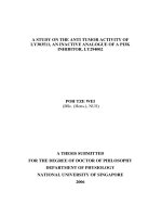
at 30 ºC. There are three models to be used
for simulation of LED heat sink, as shown
in Fig. 1: (1) without any crevice, (2) with
one crevice, and (3) with two crevices. The
substrate material for heat sinks is
aluminum having the thermal conductivity
of 237 W/(mK), density of 2,700 kg/m
3
,
and specific heat of 904 J/(kgK) [13, 14].
a) LED heat sink without crevice (Model 1)
b) LED heat sink with one crevice (Model 2)
c) LED heat sink with two crevices (Model 3)
Figure 1. Models of LED heat sinks
The 2012 International Conference on Green Technology and Sustainable Development (GTSD2012)
2.2 Experimental setup
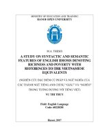
The experimental system includes a power
supply, a temperature measurement unit, a
fan, and a velocity measurement unit, as
shown in Fig. 2. The heat dissipation
patterns – fin aluminum heat sink - were
tested under different heat transfer modes:
natural convection and forced convection.
The LED with a power supply of 7W was
used in this study. Accuracies and ranges of
testing apparatuses are listed in Table 1.
Table 1. Accuracies and ranges of testing
apparatuses
Testing apparatus
Accuracy
Range
Thermocouples
0.1 C
0 100 C
Velocity meter
1 %
0 50 m/s
Figure 2. A photo of the experimental system
Experimental data obtained from the LED
heat sinks were under the constant room
temperature condition of 30 ºC. For the
case with natural convection, air velocity
was measured at 0.1 m/s; for forced
convection, air velocity was measured at
1.2 m/s. At the middle fin of the heat sink,
five thermocouples were soldered on the
top of fin to obtain the temperature
readings.
3. RESULTS AND DISCUSSION
3.1 Natural convection condition
a. For Model 1 Heat Sink Configuration
For experiments carried out in this study,
with LED capacity of 7 W and air velocity
of 0.1 m/s, heat transfer from the LED
through the heat sink was constant; the
bottom temperature of heat sink was
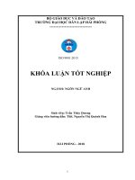
measured to be 49 ºC. Fig. 3 shows
temperature profiles of heat sink and air for
model 1 heat sink configuration.
Figure 3. Temperature profiles of heat sink and
air for Model 1 heat sink configuration
0
10
20
30
40
50
0 20 40 60 80
Temperature of the middle fin,
o
C
Fin length of LED, mm
Numerical
Experimental
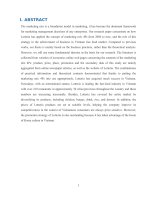
Figure 4. Comparison between numerical and
experimental results for Model 1 heat sink
configuration
Comparison between numerical and
experimental results for Model 1 heat sink
configuration is shown in Fig. 4. It is
observed that the results obtained from the
numerical simulation are in good
agreement with those obtained from the
experimental data, with the maximum
diffrence of 4.6%. The difference is due to
the error in temperature measurements
caused by temperature sensors which were
soldered at the outer rims of the fins while
The 2012 International Conference on Green Technology and Sustainable Development (GTSD2012)
the numerical results indicated more exact
phenomena taken place in the air
surrounding the heat sink.
b. For Model 2 Heat Sink Configuration
For the same experimental condition above,
with air velocity of 0.1 m/s, the bottom
temperature of heat sink was measured to
be 50.4 ºC. Temperature profiles of heat
sink and air for Model 2 heat sink
configuration are shown in Fig. 5. Fig. 6
shows the comparison between numerical
and experimental results.
Figure 5. Temperature profiles of heat sink and
air for Model 2 heat sink configuration
0
10
20
30
40
50
0 20 40 60 80
Temperature of the middle fin,
o
C
Fin length of LED, mm
Numerical
Experimental
Figure 6. Comparison between numerical and
experimental results for Model 2 heat sink
configuration
c. For Model 3 Heat Sink Configuration
With the same conditions, the bottom
temperature of heat sink was measured to
be 49.7 ºC. The Fig. 7 shows temperature
profiles of heat sink and air for Model 3
heat sink configuration.
Figure 7. Temperature profiles of heat sink and
air Model 3 heat sink configuration
0
10
20
30
40
50
0 20 40 60 80
Temperature of the middle fin,
o
C
Fin length of LED, mm
Numerical
Experimental
Figure 8. Comparison between numerical and
experimental results for Model 3 heat sink
configuration
Comparison between numerical and
experimental results for Model 3 heat sink
configuration is shown in Fig. 8. It is also
indicated that the numerical and
experimental results are in good agreement.
From Figs. 3-8, for the natural convection
case, it is observed that the bottom
temperature of heat sink for Model 1 heat
sink configuration was the lowest. It is due
to the fact that Model 1 heat sink
configuration has the largest heat transfer
area.
The 2012 International Conference on Green Technology and Sustainable Development (GTSD2012)
3.2 Forced convection condition
Experiments for forced convection
condition were done on Model 3 heat sink
configuration by using a fan with an air
velocity of 1.2 m/s.
For this case, the bottom temperature of heat
sink was measured to be 38.5 ºC. Figure 9
shows the comparison between numerical
and experimental results for the case with
forced convection. It is also indicated that
the numerical and experimental results are
in good agreement, with the maximum
discrepancy of the temperature estimated to
be less than 8 %.
From Figs. 4-9, it is shown that the heat
transfer capability obtained from the case
with forced convection is higher than that
obtained from the case with natural
convection case: at the same room
temperature condition and LED power
supply capacity, the bottom temperature of
LED heat sink is reduced from 49.7 to 38.5
ºC.
0
10
20
30
40
50
0 20 40 60 80
Temperature of the middle fin,
o
C
Fin length of LED, mm
Numerical
Experimental
Figure 9. Comparison between numerical and
experimental results for Model 3 heat sink
configuration with forced convection case
4. CONCLUSION
Numerical and experimental studies have
been performed on three LED heat sinks
with different configurations. In natural
convection case, the heat transfer capability
obtained from the heat sink without crevice
was higher than those obtained from the
heat sinks with crevice or crevices. The
heat transfer capability obtained from the
case with forced convection is higher than
that obtained from the case with natural
convection case: at the same room
temperature condition and LED power
supply capacity, the bottom temperature of
LED heat sink is reduced from 49.7 to 38.5
ºC. Furthermore, the results obtained from
the experiments were in good agreement
with those obtained from the numerical
simulations, with the maximum
discrepancy of the temperature estimated to
be less than 8 %.
5. ACKNOWLEDGEMENTS
The supports of this work by (1) the
projects (Project Nos. 54-11-CT/HD-CTTB
and 38- 12-CT/HĐ-CTTB) sponsored by
New Product & Technology Center
(NEPTECH) – Hochiminh City Department
of Science and Technology of Vietnam, (2)
the project (Project No. T2012-16TĐ
/KHCN -GV) sponsored by the specific
research fields at Hochiminh City
University of Technical Education, Vietnam,
(3) the project (Project Nos. NSC 99-2221
-E-033-025 and NSC 100-2221 -E-033-065)
sponsored by National Science Council of
the Republic of China in Taiwan, and (4)
the project (under Grant No. CYCU-98-CR
-ME) sponsored by the specific research
fields at Chung Yuan Christian University,
Taiwan, are deeply appreciated.
6. REFERENCES
[1] Christian Alvin, Jyh-tong Teng,
and Thanhtrung Dang, Thermal
Resistance Analysis of Extruded Fin
Heat Sink on LED Lamp, The
International Electron Devices and
Materials Symposium 2011
(IEDMS2011), Taipei, Taiwan, Nov
17-18, 2011, P-C-19, pp. 1-4
[2] X.B. Luo, W. Xiong, T. Cheng, and S.
Liu, Temperature estimation of
high-power light emitting diode street
lamp by a multi-chip analytical
solution, IET Optoelectron, 3, 2009, pp.
225–232
[3] L. Kim, J.H. Choi, S.H. Jang, and M.W.
The 2012 International Conference on Green Technology and Sustainable Development (GTSD2012)
Shin, Thermal analysis of LED array
system with heat pipe, 6th Symposium
of the Korean Society of
Thermophysical Properties, Seoul,
2006, pp. 21–25
[4] Zirong Lin, Shuangfeng Wang, Jiepeng
Huo, Yanxin Hu, Jinjian Chen,
Winston Zhang, and Eton Lee, Heat
transfer characteristics and LED heat
sink application of aluminum plate
oscillating heat pipes, Applied Thermal
Engineering, 31, 2011, pp. 2221-2229
[5] L.L. Yuan, S. Liu, M.X. Chen, and X.B.
Luo, Thermal analysis of high power
LED array packaging with
microchannel cooler, 7th International
Conference on Electronics Packaging
Technology, Shanghai, 2006, pp.
574–577.
[6] C.J. Weng, Advanced thermal
enhancement and management of LED
packages, International
Communications in Heat and Mass
Transfer, 37, 2009, pp. 245–248.
[7] Y. Deng and J. Liu, A liquid metal
cooling system for the thermal
management of high power LEDs
International Communications in Heat
and Mass Transfer, 37, 2010,
pp.788–791.
[8] K.Q. Ma and J. Liu, Liquid metal
cooling in thermal management of
computer chips, Front. Energy Power
Eng. China, 1, 2007, pp. 384–402.
[9] S. Liu, J.H. Yang, Z.Y. Gan and X.B.
Luo, Structural optimization of a
microjet basedcooling system for high
power LEDs, Int. J.Therm. Sci. 47,
2008, pp. 1086–1095.
[10] Thanhtrung Dang, Ngoctan Tran and
Jyh-tong Teng, Numerical and
Experimental investigations on heat
transfer phenomena of an aluminium
microchannel heat sink, Applied
Mechanics and Materials, 145, 2012,
pp. 129-133
[11] Ngoctan Tran, Thanhtrung Dang and
Jyh-tong Teng, Numerical and
experimental studies on pressure drop
and performance index of an aluminum
microchannel heat sink, 2012 IEEE
International Symposium on Computer,
Consumer and
Control (IS3C2012), June 4-6, 2012,
Taichung City, Taiwan, pp. 252-257
[12] Thanhtrung Dang and Jyh-tong Teng,
Comparison on the heat transfer and
pressure drop of the microchannel and
minichannel heat exchangers, Heat and
Mass Transfer, 47, 2011, pp.
1311-1322.
[13] J.P. Holman, Heat transfer, Ninth
Edition, McGraw-Hill, New York,
2002
[14] COMSOL Multiphysics version 3.5
(2008) – Documentation.
Contact
Thanhtrung Dang, Ph.D.
Tel: +84913606261
Email: