Daewoo matiz 2000 2013 ABS system hệ thống ABS trên xe matiz đời 2000 2013
Bạn đang xem bản rút gọn của tài liệu. Xem và tải ngay bản đầy đủ của tài liệu tại đây (818.85 KB, 57 trang )
DAEWOO M-150 BL2
SECTION 4F
ANTILOCK BRAKE SYSTEM
CAUTION: Disconnect the negative battery cable before removing or installing any electrical unit or when a
tool or equipment could easily come in contact with exposed electrical terminals. Disconnecting this cable
will help prevent personal injury and damage to the vehicle. The ignition must also be in B unless otherwise
noted.
CAUTION: Don’t diagnosis the Antilock Brake System (ABS) under the vehicle moving status. Because the
ABS function will be stopped.
TABLE OF CONTENTS
Description and Operation 4F-3. . . . . . . . . . . . . . . . . .
ABS System Components 4F-3. . . . . . . . . . . . . . . . . .
Hydraulic Unit 4F-3. . . . . . . . . . . . . . . . . . . . . . . . . . . . .
EBCM (Electronic Brake Control Module) 4F-4. . . . .
Wheel Speed Sensors and Rings 4F-5. . . . . . . . . . . .
Electronic Brake Distribution 4F-5. . . . . . . . . . . . . . . .
Indicator 4F-5. . . . . . . . . . . . . . . . . . . . . . . . . . . . . . . . .
EBCM Connector 4F-6. . . . . . . . . . . . . . . . . . . . . . . . . .
Hydraulic Fluid Flow Diagrams 4F-7. . . . . . . . . . . . . .
Normal Braking Mode 4F-7. . . . . . . . . . . . . . . . . . . .
Isolation Mode (Pressure Maintain) 4F-8. . . . . . . .
Dump Mode (Pressure Decrease) 4F-9. . . . . . . . .
Reapply Mode (Pressure Increase) 4F-10. . . . . . .
Proportioning Function 4F-11. . . . . . . . . . . . . . . . . .
Visual Identification 4F-12. . . . . . . . . . . . . . . . . . . . . . .
EBCM Connector Face View 4F-12. . . . . . . . . . . . . . .
Component Locator 4F-13. . . . . . . . . . . . . . . . . . . . . . .
ABS 4F-13. . . . . . . . . . . . . . . . . . . . . . . . . . . . . . . . . . . .
Diagnostic Information and Procedures 4F-16. . . .
DTC 0354 Left Front Wheel Speed Sensor
Circuit Open or Shorted 4F-16. . . . . . . . . . . . . . . . .
DTC 0355 Left Front Wheel Speed Sensor
Poor Air Gap or Missing Tooth Ring 4F-20. . . . . . .
DTC 0356 Left Front Wheel Speed Sensor
Circuit Intermittent Shorted 4F-22. . . . . . . . . . . . . .
DTC 0404 Right Front Wheel Speed Sensor
Circuit Open or Shorted 4F-24. . . . . . . . . . . . . . . . .
DTC 0405 Right Front Wheel Speed Sensor
Poor Air Gap or Missing Tooth Ring 4F-28. . . . . . .
DTC 0406 Right Front Wheel Speed Sensor
Circuit Intermittent Shorted 4F-30. . . . . . . . . . . . . .
DTC 0454 Left Rear Wheel Speed Sensor
Circuit Open or Shorted 4F-32. . . . . . . . . . . . . . . . .
DTC 0455 Left Rear Wheel Speed Sensor
Poor Air Gap or Missing Tooth Ring 4F-36. . . . . . .
DTC 0456 Left Rear Wheel Speed Sensor
Circuit Intermittent Shorted 4F-38. . . . . . . . . . . . . .
DTC 0504 Right Rear Wheel Speed Sensor
Circuit Open or Shorted 4F-42. . . . . . . . . . . . . . . . .
DTC 0505 Right Rear Wheel Speed Sensor
Poor Air Gap or Missing Tooth Ring 4F-46. . . . . . .
DTC 0506 Right Rear Wheel Speed Sensor
Circuit Intermittent Shorted 4F-48. . . . . . . . . . . . . .
DTC 0601 Left Front Dump Shorted or
Driver Open 4F-52. . . . . . . . . . . . . . . . . . . . . . . . . . .
DTC 0602 Left Front Dump Open or
Driver Shorted 4F-54. . . . . . . . . . . . . . . . . . . . . . . . .
DTC 0651 Left Front Isolation Shorted or
Driver Open 4F-56. . . . . . . . . . . . . . . . . . . . . . . . . . .
DTC 0652 Left Front Isolation Open or
Driver Shorted 4F-58. . . . . . . . . . . . . . . . . . . . . . . . .
DTC 0701 Right Front Dump Shorted or
Driver Open 4F-60. . . . . . . . . . . . . . . . . . . . . . . . . . .
DTC 0702 Right Front Dump Open or
Driver Shorted 4F-62. . . . . . . . . . . . . . . . . . . . . . . . .
DTC 0751 Right Front Isolation Shorted or
Driver Open 4F-64. . . . . . . . . . . . . . . . . . . . . . . . . . .
DTC 0752 Right Front Isolation Open or
Driver Shorted 4F-66. . . . . . . . . . . . . . . . . . . . . . . . .
DTC 0801 Left Rear Dump Shorted or
Driver Open 4F-68. . . . . . . . . . . . . . . . . . . . . . . . . . .
DTC 0802 Left Rear Dump Open or
Driver Shorted 4F-70. . . . . . . . . . . . . . . . . . . . . . . . .
DTC 0851 Left Rear Isolation Shorted or
Driver Open 4F-72. . . . . . . . . . . . . . . . . . . . . . . . . . .
DTC 0852 Left Rear Isolation Open or
Driver Shorted 4F-74. . . . . . . . . . . . . . . . . . . . . . . . .
DTC 0901 Right Rear Dump Shorted or
Driver Open 4F-76. . . . . . . . . . . . . . . . . . . . . . . . . . .
DTC 0902 Right Rear Dump Open or
Driver Shorted 4F-78. . . . . . . . . . . . . . . . . . . . . . . . .
4F–2 ANTILOCK BRAKE SYSTEM
DAEWOO M-150 BL2
DTC 0951 Right Rear Isolation Shorted or
Driver Open 4F-80. . . . . . . . . . . . . . . . . . . . . . . . . . .
DTC 0952 Right Rear Isolation Open or
Driver Shorted 4F-82. . . . . . . . . . . . . . . . . . . . . . . . .
DTC 1102 Return Pump Motor Circuit Open 4F-84. .
DTC 1103 Return Pump Motor Relay Fault 4F-86. . .
DTC 1104 Return Pump Motor Circuit
Shorted 4F-88. . . . . . . . . . . . . . . . . . . . . . . . . . . . . . .
DTC 1211 EBCM Main Relay Shorted 4F-90. . . . . . .
DTC 1212 EBCM Main Relay Open 4F-92. . . . . . . . .
DTC 1213 EBCM Main Relay Fault 4F-94. . . . . . . . .
DTC 1610 Stoplamp Switch Circuit Open 4F-96. . . .
DTC 2321 ABS (Amber) Indicator Shorted
to Battery 4F-100. . . . . . . . . . . . . . . . . . . . . . . . . . . .
DTC 2322 ABS (Amber) Indicator Shorted
to Ground 4F-104. . . . . . . . . . . . . . . . . . . . . . . . . . . .
DTC 2458 Wheel Speed Sensor
Intermittent Error 4F-107. . . . . . . . . . . . . . . . . . . . . .
DTC 2459 Wheel Speed Sensor Excessive
Wheel Speed Variation 4F-108. . . . . . . . . . . . . . . . .
DTC 2520 EBCM Internal Fault 4F-110. . . . . . . . . . .
DTC 5501 Vehicle Inhibit Code 4F-112. . . . . . . . . . . .
DTC 5502 Isolation Valve Time–Out 4F-114. . . . . . .
DTC 5503 CPU Loop Time Error 4F-115. . . . . . . . . .
DTC 5504 Excessive Dump Valve Time 4F-116. . . .
DTC 5560 Inoperative External Watch–Dog 4F-117.
DTC 5610 RAM/ROM Error 8 Bit 4F-118. . . . . . . . . .
DTC 5630 ROM Error 16 Bit 4F-119. . . . . . . . . . . . . .
DTC 5640 RAM Error 16 Bit 4F-120. . . . . . . . . . . . . .
DTC 8001 Battery High Voltage Fault
(More Than 16V) 4F-122. . . . . . . . . . . . . . . . . . . . . .
DTC 8002 Battery Low Voltage Fault
(Less Than 9V) 4F-124. . . . . . . . . . . . . . . . . . . . . . .
DTC 8003 Battery Low Voltage Fault
(Less Than 9.5V) 4F-126. . . . . . . . . . . . . . . . . . . . . .
Repair Instructions 4F-128. . . . . . . . . . . . . . . . . . . . . . .
On-Vehicle Service 4F-128. . . . . . . . . . . . . . . . . . . . . . . .
Service Precautions 4F-128. . . . . . . . . . . . . . . . . . . . .
Bleeding System 4F-128. . . . . . . . . . . . . . . . . . . . . . . .
Front Wheel Speed Sensor 4F-129. . . . . . . . . . . . . . .
Rear Wheel Speed Sensor 4F-130. . . . . . . . . . . . . . .
Front Wheel Speed Ring 4F-131. . . . . . . . . . . . . . . . .
Rear Wheel Speed Ring 4F-131. . . . . . . . . . . . . . . . . .
Hydraulic Modulator and Upper/Lower
Mounting Bracket 4F-132. . . . . . . . . . . . . . . . . . . . . .
EBCM (Electronic Brake Control Module) 4F-134. . .
Specifications 4F-136. . . . . . . . . . . . . . . . . . . . . . . . . . .
General Specifications 4F-136. . . . . . . . . . . . . . . . . . .
Fastener Tightening Specifications 4F-136. . . . . . . . .
Special Tools and Equipment 4F-136. . . . . . . . . . . . .
Special Tools Table 4F-136. . . . . . . . . . . . . . . . . . . . . .
Schematic and Routing Diagrams 4F-137. . . . . . . . .
ABS Circuit 4F-137. . . . . . . . . . . . . . . . . . . . . . . . . . . . .
ABS Block Diagram 4F-140. . . . . . . . . . . . . . . . . . . . . .
ANTILOCK BRAKE SYSTEM 4F–3
DAEWOO M-150 BL2
DESCRIPTION AND OPERATION
ABS SYSTEM COMPONENTS
The Antilock Braking System (ABS) consists of a con-
ventional hydraulic brake system plus antilock compo-
nents. The conventional brake system includes a
vacuum booster, master cylinder, front disc brakes, rear
drum brakes, interconnecting hydraulic brake pipes and
hoses, brake fluid level sensor and the BRAKE indicator.
The ABS components include a hydraulic unit, an elec-
tronic brake control module (EBCM), two system fuses,
four wheel speed sensors (one at each wheel), intercon-
necting wiring, the ABS indicator, and the rear drum
brake. See “ABS Component Locator” in this section for
the general layout of this system.
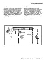
HYDRAULIC UNIT
The hydraulic unit with the attached EBCM is located
between the surge tank and the fire wall on the right side
of the vehicle. The basic hydraulic unit configuration
consists of return pump motor, return pump, four isola-
tion valves, four dump valves, two Low Pressure Accu-
mulators (LPA), two High Pressure Attenuators (HPA).
The hydraulic unit controls hydraulic pressure to the
front calipers and rear wheel cylinders by modulating hy-
draulic pressure to prevent wheel lockup.
Isolation valve
The isolation valve is placed in the brake fluid path from
the master cylinder to the relevant brake caliper and al-
lows free flow as commanded by the driver during nor-
mal braking and reapply phases.
In the isolation phase the coil moves the armature down,
which closes the normally open isolation orifice and pre-
vents any further increase of pressure in the brake. The
valve also remains closed during the dump phase.
The lip seal provides a one way return path for brake
fluid to flow through in:
1. Foot off pedal during isolation.
2. Residual LPA fluid.
D107E002
Dump Valve
The dump valve creates a flow path from the isolation
cartridge (brake side) to the low pressure accumulator
(LPA). The valve keeps this path permanently closed ex-
cept during the dump phase in the ABS mode. On ac-
tivation (dump phase), the coil moves up the armature
which opens the normally closed dump orifice and allow
to drain the pressure in the brake line with the brake fluid
flowing into the LPA.
The lip seal provides a return path for residual brake
fluid in the LPA.
D107E003
Low Pressure Accumulator (LPA)
LPA provides a variable chamber for brake fluid to be
quickly pushed in through the dump valve at the begin-
ning of a departure. This chamber then acts as a reser-
voir which buffers the pump.
D107E004
High Pressure Attenuator (HPA)
The HPA is in between the pump and the ISO valve
(master cylinder side) and uses the bulk mode of the
contained plastic damper and orifice size to dump out
the pressure oscillations from the pump to reduce the
4F–4 ANTILOCK BRAKE SYSTEM
DAEWOO M-150 BL2
feed back to the master cylinder and brake pedal.
D107E005
Return Pump Motor
The motor drives two pump elements through the ec-
centric wheel on its shaft.
Return Pump
Description: Each pump element consists of a fixed
displacement piston driven by an eccentric on the end of
the eccentric motor. It has two check valves (inlet and
outlet) and is fed with fluid by the low pressure accumu-
lator.
Operation:
Compression stroke: the pump is filled via the inlet ball
seat, then the motor eccentric rotates moving the piston
to displace the fluid. After the pressure build-up closes
the inlet valve the piston displacement increases the
pressure until the outlet ball opens. The outlet pressure
will continue to increase for the rest of the piston stroke.
Return Stroke: The piston retracts, forced by its spring,
as the motor eccentric returns to its low end position.
The pressure at the inlet side of the outlet ball then de-
creases due to the displaced volume and the pressure
difference across this ball holds it closed.
The pressure at the outlet side of the inlet ball seat,
which is set to open at a certain pressure level also de-
creases until this valve opens. With the outlet ball
closed, the pump is filled with additional fluid from the
low pressure accumulator.
The pressure will continue until a stall point is reached
and compression of the piston cannot generate enough
differential pressure anymore to open the outlet ball
seat.
D17E006A
Return Pump
Return Pump
Motor
(0.12~0.16 in.)
EBCM (ELECTRONIC BRAKE
CONTROL MODULE)
Notice: There is no serviceable. The EBCM must be re-
placed as an assembly.
The EBCM is attached to the hydraulic unit in the engine
compartment. The controlling element of ABS is a mi-
croprocessor-based EBCM. Inputs to the system in-
clude the four wheel speed sensors, the stoplamp
switch, the ignition switch, and the unswitched battery
voltage. There is an output to a bi-directional serial data
link, located in pin M of the assembly line diagnostic link
(ALDL), for service diagnostic tools and assembly plat
testing.
The EBCM monitors the speed of each wheel. If any
wheel begins to approach lockup and the brake switch is
closed (brake pedal depressed), the EBCM controls the
dump valve to reduce brake pressure to the wheel ap-
proaching lockup. Once the wheel regains traction,
brake pressure is increased until the wheel again begins
to approach lockup. The cycle repeats until either the
vehicle comes to a stop, the brake pedal is released or
no wheels approach lockup.
Additionally, the EBCM monitors itself, each input (ex-
cept the serial data link), and each output for proper op-
eration. If it detects any system malfunction, the EBCM
will store a DTC in nonvolatile memory (DTCs will not
disappear if the battery is disconnected).
ANTILOCK BRAKE SYSTEM 4F–5
DAEWOO M-150 BL2
D107E001
WHEEL SPEED SENSORS AND
RINGS
Front wheel speed sensors are installed to the front
knuckle and rear wheel speed sensors are installed to
the backing plate.
Wheel speed sensors are no serviceable. And the air
cap is not adjusted. Front wheel speed sensor ring is
pressed onto the drive axle shaft. Each ring contains 40
equally spaced teeth. Exercise care during service pro-
cedures to avoid prying or contacting this ring. Exces-
sive contact may cause damage to one or more teeth.
Rear wheel speed sensor rings are incorporated into the
hub drum.
D107E007
D107E008
ELECTRONIC BRAKE DISTRIBUTION
ABS features an enhanced algorithm which includes
control of the brake force distribution between the front
and rear axles. This is called Electronic Brake Distribu-
tion or Dynamic Rear Proportioning valve. In an unladen
car condition the brake efficiency is comparable to the
conventional system but for a fully loaden vehicle the ef-
ficiency of the Dynamic Rear Proportioning System is
higher due to the better use of rear axle braking capabili-
ty.
No indication is given to the driver when Dynamic Rear
Proportioning is activated. Also, DRP remains active
even in such cases where the anti-lock function of the
ABS is disabled.
D17E009A
Critical Brake Points
Ideal Distribution
Fully Laden Vehicle
Ideal Distribution
Lightly Loaded
Vehicle
Advanced Distribution with ABS
Regular Distribution without Dynamic
Rear Proportioning
Relative Front Brake Force
INDICATOR
It illuminates for four seconds immediately after the igni-
tion has been turned on to show that the anti-lock sys-
tem self-test is being carried out. If the light does not go
off after this time it means that there may be a problem
and ABS operation is not available.
If any malfunction or error, including an unplugged
EBCM connector, is detected during vehicle operation,
the light will come on, warning the driver that the ABS is
not operative and brake operation is in conventional,
non-ABS mode.
D17E010A
4F–6 ANTILOCK BRAKE SYSTEM
DAEWOO M-150 BL2
EBCM CONNECTOR
A Connector has 31 pins which are shown below figure.
And a connector includes a warning switch which
grounds and lights the ABS warning lamp if there is No
EBCM unit plugged in, so that an indication is given that
ABS is not available.
D17E011A
Mechanical Switch
ANTILOCK BRAKE SYSTEM 4F–7
DAEWOO M-150 BL2
HYDRAULIC FLUID FLOW DIAGRAMS
Master Cylinder
High Pressure Attenuator
High Pressure Attenuator
Return Pump Motor
Return Pump
Return Pump
RR
Isolation Valve
Low
Pressure
Accumulator
FL
Isolation Valve
RR Dump Valve
FL
Dump
Valve
FR
Isolation Valve
Low Pressure
Accumulator
FR Dump Valve
RL
Dump
Valve
RL
Isolation
Valve
RR FL FR RL
D17E205A
NORMAL BRAKE MODE
During non-antilock braking, pressure is applied through the brake pedal and fluid comes from the master cylinder into
the hydraulic unit. The normally open isolation cartridge and normally closed dump cartridge would remain in these
positions to allow fluid pressure to the calipers and the wheel cylinders. And each wheel begins locking.
4F–8 ANTILOCK BRAKE SYSTEM
DAEWOO M-150 BL2
Master Cylinder
High Pressure Attenuator
High Pressure Attenuator
Return Pump Motor
Return Pump
Return Pump
Low
Pressure
Accumulator
Low Pressure
Accumulator
RR
FL FR
RL
D17E206A
RR
Isolation Valve
FL
Isolation Valve
RR Dump Valve
FL
Dump
Valve
FR
Isolation Valve
FR Dump Valve
RL
Dump
Valve
RL
Isolation
Valve
ISOLATION MODE (PRESSURE MAINTAIN)
If the information from the wheel speed sensors indicate excessive wheel deceleration (imminent lockup), the first step
in the antilock sequence is to isolate the brake pressure being applied by the driver. The EBCM sends a voltage to the
coil to energize and close the isolation valves by pulling down on the armature. This prevents any additional fluid pres-
sure applied by the driver from reaching the wheel. Though each channel of the 4-channel system can operate inde-
pendently, once any front channel (brake) sees excessive deceleration, both front isolation valves are energized and
close thus, with the isolation valves closed, further unnecessary increases in the brake pressure will be prohibited.
ANTILOCK BRAKE SYSTEM 4F–9
DAEWOO M-150 BL2
Master Cylinder
High Pressure Attenuator
High Pressure Attenuator
Return Pump Motor
Return Pump
Return Pump
Low
Pressure
Accumulator
Low Pressure
Accumulator
RR
FL FR
RL
D17E207A
RR
Isolation Valve
FL
Isolation Valve
RR Dump Valve
FL
Dump
Valve
FR
Isolation Valve
FR Dump Valve
RL
Dump
Valve
RL
Isolation
Valve
DUMP MODE (PRESSURE DECREASE)
Once the pressure is isolated, it must be reduced to get the wheels rolling once again. This is accomplished by dump-
ing a portion of the brake fluid pressure into a low pressure accumulator (LPA).
The EBCM energizes the dump cartage coil(s) to open the dump cartridge, allowing fluid from the wheels to be
dumped into the LPA. This done with very short activation pulses opening and closing the dump cartridge passageway.
Brake pressure is lowered at the wheel and allows the wheel to begin spinning again.
The fluid taken from the wheels forces the spring back and is stored in the LPA. A portion of the fluid also primes the
pump. The dump cartridges are operated independently to control the deceleration of the wheel.
4F–10 ANTILOCK BRAKE SYSTEM
DAEWOO M-150 BL2
Master Cylinder
High Pressure Attenuator
Return Pump Motor
Return Pump
Return Pump
Low Pressure
Accumulator
RR
FL FR
RL
D17E208A
RR
Isolation Valve
Low
Pressure
Accumulator
FL
Isolation Valve
RR Dump Valve
FL
Dump
Valve
FR
Isolation Valve
FR Dump Valve
RL
Dump
Valve
RL
Isolation
Valve
High Pressure Attenuator
REAPPLY MODE (PRESSURE INCREASE)
This reapply sequence is initiated to obtain optimum braking. The isolation valve is momentarily pumped open to allow
master cylinder and pump pressure to reach the brakes. This controlled pressure rise continues unitl the wheel is at
optimum brake output or until the brake pressure is brough up to the master cylinder output pressure.
If more pressure is required, more fluid is drawn from the master cylinder and applied to the brakes. The driver may
feel slight pedal pulsations, or pedal drop, this is normal and expected.
As fluid is reapplied to the wheel, they begin to slow down. If they approach imminent lockup again, the EBCM will
isolate, dump and reapply again. The control cycle (isolation, dump, reapply) occurs in milli-second intervals, allowing
seveal cycles to occur each second.
It is a much faster and more controlled way of “pumping the pedal”.
ANTILOCK BRAKE SYSTEM 4F–11
DAEWOO M-150 BL2
Master Cylinder
High Pressure Attenuator
High Pressure Attenuator
Return Pump Motor
Return Pump
Return Pump
Low Pressure
Accumulator
RR
FL FR
RL
D17E209A
RR
Isolation Valve
Low
Pressure
Accumulator
FL
Isolation Valve
RR Dump Valve
FL
Dump
Valve
FR
Isolation Valve
FR Dump Valve
RL
Dump
Valve
RL
Isolation
Valve
PROPORTIONING FUNCTION
If the rear wheels lock formerly during braking, the vehicle may lose the stability. Therefore to prevent this, the ECM
processes the speed sensor signal and brake signal to determine when the rear wheels are tending to lock up. The
EBCM then actuates the rear wheel isolation valves to reduce the rear brake pressure and keep the wheels rolling.
4F–12 ANTILOCK BRAKE SYSTEM
DAEWOO M-150 BL2
VISUAL IDENTIFICATION
EBCM CONNECTOR FACE VIEW
Terminal 9 is identified as they appear from the wire entry end of the harness connector.
EBCM Connector
D107E204
Pin Signal Name Color Circuit
2 ROUGH ROAD GRY/YEL Buffered Wheel Speed Signal : to ECM–55
(Sirius D3)
9 RRWSHI BRN Right Rear Wheel Speed High
10 RRWSLO WHT Right Rear Wheel Speed Low
11 SDLUART BRN/DK GRN Serial Data Link
12 RFWSHI DK GRN/BLK Right Front Wheel Speed High
13 RFWSLO BRN/DK GRN Right Front Wheel Speed Low
14 LFWSHI DK BLU Left Front Wheel Speed High
15 IGN RED/YEL Switched Ignition
16 GND BLK Negative Battery Terminal
17 BATT RED Battery
18 BATT RED Battery
19 GND BLK Negative Battery Terminal
20 ABSWARN DK GRN/GRY ABS Warning Indicator
22 LRWSHI BLK Left Rear Wheel Speed High
23 LRWSLO RED Left Rear Wheel Speed Low
24 BRAKESW YEL Brake Switch
25 LFWSLO YEL Left Front Wheel Speed Low
ANTILOCK BRAKE SYSTEM 4F–13
DAEWOO M-150 BL2
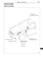
COMPONENT LOCATOR
ABS
D17E401A
1. Hydraulic Modulator Unit
2. Electronic Brake Control Module (EBCM)
3. Bolt
4. Upper Mounting Bracket
5. Grommet
6. Lower Mounting Bracket
7. Bracket Grommet
8. Rear Wheel Speed Sensor
9. Front Wheel Speed Sensor
4F–14 ANTILOCK BRAKE SYSTEM
DAEWOO M-150 BL2
ABS (Cont’d)
D17E402A
ANTILOCK BRAKE SYSTEM 4F–15
DAEWOO M-150 BL2
BLANK
4F–16 ANTILOCK BRAKE SYSTEM
DAEWOO M-150 BL2
DIAGNOSTIC INFORMATION AND PROCEDURES
D17E301A
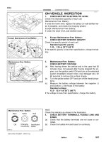
DIAGNOSTIC TROUBLE CODE (DTC) 0354
LEFT FRONT WHEEL SPEED SENSOR CIRCUIT OPEN OR SHORTED
Circuit Description
As a toothed ring passes by the wheel speed sensor,
changes in the electromagnetic field cause the wheel
speed sensor to produce a sinusoidal (AC) voltage sig-
nal whose frequency is proportional to the wheel speed.
The magnitude of this signal is directly related to wheel
speed and the proximity of the wheel speed sensor to
the toothed ring often referred to as the air gap.
Diagnosis
This test detects a short to battery, ground, or open in
the left front wheel speed sensor circuit.
Cause(s)
D The wheel speed circuit is open or shorted to the bat-
tery or ground.
D There is a loose connection in the wheel speed cir-
cuit.
D The wheel speed sensor resistance is very high.
D The EBCM is malfunctioning.
Fail Action
This is a critical operational fault. The ABS is disabled
and the ABS warning lamp is turned on. The proportion-
ing is operation.
Diagnostic Aids
An ‘‘intermittent’’ malfunction may be caused by a poor
connection, rubbed through wire insulation, or a wire
that is broken inside the insulation.
Thoroughly check any circuitry suspected of causing the
intermittent complaint. Look for backed out terminals,
improper mating, broken locks, improperly formed or
damaged terminals, poor terminal to wiring connections,
or physical damage to the wiring harness.
Wheel speed sensor resistance will increase as the sen-
sor temperature increases.
When replacing a wheel speed sensor, inspect the sen-
sor terminals and harness connector for corrosion and/
or water intrusion. If evidence of corrosion or water
ANTILOCK BRAKE SYSTEM 4F–17
DAEWOO M-150 BL2
intrusion exists, replace the wheel speed sensor har-
ness. If replacing a wheel speed sensor harness, in-
spect the sensor terminals. If you find evidence of
corrosion or water intrusion, replace the wheel speed
sensor. Refer to “Front Wheel Speed Sensor” in this
section.
Important: Wheel speed sensor intermittent malfunc-
tions may be difficult to locate. Take care not to disturb
any electrical connections before performing an indi-
cated step of this table. That will ensure that an intermit-
tent connection will not be corrected before the source
of the malfunction is found.
DTC 0354 – Left Front Wheel Speed Sensor Circuit Open or Shorted
Step Action Value(s) Yes No
1
1. Turn the ignition switch to OFF.
2. Disconnect the EBCM harness connector from
the EBCM.
3. Use a digital voltmeter (DVM) to measure the
resistance between terminals 14 and 25 of
connector on the EBCM harness.
Is the resistance within the specified value? 1.0 kW to
1.5 kW
Go to Step 4 Go to Step 2
2
1. Disconnect the harness from the left front wheel
speed sensor.
2. Use a DVM to measure the resistance between
terminals 1 and 2 of the left front wheel speed
sensor connector.
Is the resistance within the specified value? 1.0 kW to
1.5 kW
Go to Step 4 Go to Step 3
3
Replace the wheel speed sensor.
Is the repair complete?
–
System OK
–
4
Use a DVM to measure the resistance between ter-
minal 14 of the EBCM harness connector, and termi-
nal 1 of the left front wheel speed sensor harness
connector.
Is the resistance within the specified value? less than 1W Go to Step 6 Go to Step 5
5
1. Repair the high resistance in circuit DK BLU.
2. If the wheel speed sensor harness is damaged,
replace it.
Is the repair complete?
–
System OK
–
6
Use a DVM to measure the resistance between ter-
minal 25 of the EBCM harness connector, and termi-
nal 2 of the left front wheel speed sensor harness
connector.
Is the resistance within the specified value? less than 1W Go to Step 8 Go to Step 7
7
1. Repair the high resistance in circuit YEL.
2. If the wheel speed sensor harness is damaged,
replace it.
Is the repair complete?
–
System OK
–
8
Use a DVM to measure the resistance between
ground and terminal 14 of the EBCM connector.
Does the DVM show the specified value? 1 Go to Step 10 Go to Step 9
9
Repair the short to ground in circuit DK BLU.
Is the repair complete?
–
System OK
–
4F–18 ANTILOCK BRAKE SYSTEM
DAEWOO M-150 BL2
DTC 0354 – Left Front Wheel Speed Sensor Circuit Open or Shorted (Cont’d)
Step Action Value(s) Yes No
10
Use a DVM to measure the resistance between
ground and terminal 25 of the EBCM connector.
Does the DVM show the specified value? 1 Go to Step 12 Go to Step 11
11
Repair the short to ground in circuit YEL.
Is the repair complete?
–
System OK
–
12
1. Reconnect all of the connectors.
2. Turn the ignition to ON.
3. Use a DVM to measure the voltage between
ground and terminal 14 of EBCM connector.
Is the voltage within the specified value? 0 v Go to Step 14 Go to Step 13
13
Repair the short to voltage in circuit DK BLU.
Is the repair complete?
–
System OK
–
14
Use a DVM to measure the voltage between ground
and terminal 25 of EBCM connector.
Is the voltage within the specified value? 0 v Go to Step 16 Go to Step 15
15
Repair the short to voltage in circuit YEL.
Is the repair complete?
–
System OK
–
16
Replace the EBCM.
Is the repair complete?
–
System OK
–
ANTILOCK BRAKE SYSTEM 4F–19
DAEWOO M-150 BL2
BLANK
4F–20 ANTILOCK BRAKE SYSTEM
DAEWOO M-150 BL2
D17E301A
DIAGNOSTIC TROUBLE CODE (DTC) 0355
LEFT FRONT WHEEL SPEED SENSOR POOR
AIR GAP OR MISSING TOOTH RING
Circuit Description
As a toothed ring passes by the wheel speed sensor,
changes in the electromagnetic field cause the wheel
speed sensor to produce a sinusoidal (AC) voltage sig-
nal whose frequency is proportional to the wheel speed.
The magnitude of this signal is directly related to wheel
speed and the proximity of the wheel speed sensor to
the toothed ring often referred to as the air gap.
Diagnosis
This test checks for the left front wheel speed equal to 0
km/h (0 mph) for greater than 6 km/h (3.8 mph).
Cause(s)
D The tooth ring is missing.
D The air gap exceeds the required specifications.
Fail Action
This is a critical operational fault. The ABS is disabled
and the ABS warning lamp is turned on. The proportion-
ing is operation.
Diagnostic Aids
An ‘‘intermittent’’ malfunction may be caused by a poor
connection, rubbed through wire insulation, or a wire
that is broken inside the insulation.
Thoroughly check any circuitry suspected of causing the
intermittent complaint. Look for backed out terminals,
improper mating, broken locks, improperly formed or
damaged terminals, poor terminal to wiring connections,
or physical damage to the wiring harness.
Wheel speed sensor resistance will increase as the sen-
sor temperature increases.
When replacing a wheel speed sensor, inspect the sen-
sor terminals and harness connector for corrosion and/
or water intrusion. If evidence of corrosion or water
intrusion exists, replace the wheel speed sensor har-
ness. If replacing a wheel speed sensor harness, in-
spect the sensor terminals. If you find evidence of
corrosion or water intrusion, replace the wheel speed
ANTILOCK BRAKE SYSTEM 4F–21
DAEWOO M-150 BL2
sensor. Refer to “Front Wheel Speed Sensor” in this
section.
Important: Wheel speed sensor intermittent malfunc-
tions may be difficult to locate. Take care not to disturb
any electrical connections before performing an indi-
cated step of this table. That will ensure that an intermit-
tent connection will not be corrected before the source
of the malfunction is found.
DTC 0355 – Left Front Wheel Speed Sensor poor air Gap or Missing Tooth Ring
Step Action Value(s) Yes No
1
1. Turn the ignition switch to OFF.
2. Physically inspect the following components for
damage.
D Wheel speed sensor is loose.
D The air gap exceeds the required specifica-
tions.
D The speed ring is missing or damaged.
3. Repair or replace the damaged.
Is the repair complete?
–
System OK Go to Step 2
2
Replace the EBCM.
Is the repair complete?
–
System OK
–
4F–22 ANTILOCK BRAKE SYSTEM
DAEWOO M-150 BL2
D17E301A
DIAGNOSTIC TROUBLE CODE (DTC) 0356
LEFT FRONT WHEEL SPEED SENSOR CIRCUIT
INTERMITTENT SHORTED
Circuit Description
As a toothed ring passes by the wheel speed sensor,
changes in the electromagnetic field cause the wheel
speed sensor to produce a sinusoidal (AC) voltage sig-
nal whose frequency is proportional to the wheel speed.
The magnitude of this signal is directly related to wheel
speed and the proximity of the wheel speed sensor to
the toothed ring often referred to as the air gap.
Diagnosis
This test intermittent the left front wheel speed sensor
circuit.
Cause(s)
D The wheel speed sensor is intermittent shorted to the
battery or ground.
D There is a loose connection in the wheel speed sen-
sor circuit.
D There is a loose connection in the EBCM.
D The EBCM is malfunctioning.
Fail Action
This is a critical operational fault. The ABS is disabled
and the ABS warning lamp repeat intermittent turned on,
and off. The proportioning is operation.
Diagnostic Aids
An ‘‘intermittent’’ malfunction may be caused by a poor
connection, rubbed through wire insulation, or a wire
that is broken inside the insulation.
Thoroughly check any circuitry suspected of causing the
intermittent complaint. Look for backed out terminals,
improper mating, broken locks, improperly formed or
damaged terminals, poor terminal to wiring connections,
or physical damage to the wiring harness.
Wheel speed sensor resistance will increase as the sen-
sor temperature increases.
When replacing a wheel speed sensor, inspect the sen-
sor terminals and harness connector for corrosion and/
or water intrusion. If evidence of corrosion or water
ANTILOCK BRAKE SYSTEM 4F–23
DAEWOO M-150 BL2
intrusion exists, replace the wheel speed sensor har-
ness. If replacing a wheel speed sensor harness, in-
spect the sensor terminals. If you find evidence of
corrosion or water intrusion, replace the wheel speed
sensor. Refer to “Front Wheel Speed Sensor” in this
section.
Important: Wheel speed sensor intermittent malfunc-
tions may be difficult to locate. Take care not to disturb
any electrical connections before performing an indi-
cated step of this table. That will ensure that an intermit-
tent connection will not be corrected before the source
of the malfunction is found.
DTC 0356 – Left Front Wheel Speed Sensor Circuit Intermittent Shorted
Step Action Value(s) Yes No
1
1. Turn the ignition switch to OFF.
2. Disconnect the EBCM harness connector from
the EBCM.
3. Use a digital voltmeter (DVM) to measure the
resistance between terminals 14 and 25 of
connector on the EBCM harness.
Is the resistance within the specified value?
1.0 kW to
1.5 kW
Go to Step 4 Go to Step 2
2
1. Disconnect the harness from the left front wheel
speed sensor.
2. Use a DVM to measure the resistance between
terminals 1 and 2 of the left front wheel speed
sensor connector.
Is the resistance within the specified value? 1.0 kW to
1.5 kW
Go to Step 4 Go to Step 3
3
Replace the wheel speed sensor.
Is the repair complete?
–
System OK
–
4
Use a DVM to measure the resistance between
ground and terminal 14 of the EBCM connector.
Does the DVM show the specified value? 1 Go to Step 6 Go to Step 5
5
Repair the short to ground in circuit DK BLU.
Is the repair complete?
–
System OK
–
6
Use a DVM to measure the resistance between
ground and terminal 25 of the EBCM connector.
Does the DVM show the specified value? 1 Go to Step 8 Go to Step 7
7
Repair the short to ground in circuit YEL.
Is the repair complete?
–
System OK
–
8
1. Turn the ignition switch to ON.
2. Use a DVM to measure the voltage between
ground and terminal 14 of the EBCM connector.
Is the voltage within the specified value? 0 v Go to Step 10 Go to Step 9
9
Repair the short to voltage in circuit DK BLU.
Is the repair complete?
–
System OK
–
10
Use a DVM to measure the resistance between
ground and terminal 25 of the EBCM connector.
Does the voltage within the specified value? 0 v Go to Step 12 Go to Step 11
11
Repair the short to voltage in circuit YEL.
Is the repair complete?
–
System OK
–
12
Replace the EBCM.
Is the repair complete?
–
System OK
–
4F–24 ANTILOCK BRAKE SYSTEM
DAEWOO M-150 BL2
D17E302A
DIAGNOSTIC TROUBLE CODE (DTC) 0404
RIGHT FRONT WHEEL SPEED SENSOR CIRCUIT OPEN OR SHORTED
Circuit Description
As a toothed ring passes by the wheel speed sensor,
changes in the electromagnetic field cause the wheel
speed sensor to produce a sinusoidal (AC) voltage sig-
nal whose frequency is proportional to the wheel speed.
The magnitude of this signal is directly related to wheel
speed and the proximity of the wheel speed sensor to
the toothed ring often referred to as the air gap.
Diagnosis
This test detects a short to battery, ground, or open in
the right front wheel speed sensor circuit.
Cause(s)
D The wheel speed circuit is open or shorted to the bat-
tery or ground.
D There is a loose connection in the wheel speed cir-
cuit.
D The wheel speed sensor resistance is very high.
D The EBCM is malfunctioning.
Fail Action
This is a critical operational fault. The ABS is disabled
and the ABS warning lamp is turned on. The proportion-
ing is operation.
Diagnostic Aids
An ‘‘intermittent’’ malfunction may be caused by a poor
connection, rubbed through wire insulation, or a wire
that is broken inside the insulation.
Thoroughly check any circuitry suspected of causing the
intermittent complaint. Look for backed out terminals,
improper mating, broken locks, improperly formed or
damaged terminals, poor terminal to wiring connections,
or physical damage to the wiring harness.
Wheel speed sensor resistance will increase as the sen-
sor temperature increases.
When replacing a wheel speed sensor, inspect the sen-
sor terminals and harness connector for corrosion and/
or water intrusion. If evidence of corrosion or water
ANTILOCK BRAKE SYSTEM 4F–25
DAEWOO M-150 BL2
intrusion exists, replace the wheel speed sensor har-
ness. If replacing a wheel speed sensor harness, in-
spect the sensor terminals. If you find evidence of
corrosion or water intrusion, replace the wheel speed
sensor. Refer to “Front Wheel Speed Sensor” in this
section.
Important: Wheel speed sensor intermittent malfunc-
tions may be difficult to locate. Take care not to disturb
any electrical connections before performing an indi-
cated step of this table. That will ensure that an intermit-
tent connection will not be corrected before the source
of the malfunction is found.
DTC 0404 – Right Front Wheel Speed Sensor Circuit Open or Shorted
Step Action Value(s) Yes No
1
1. Turn the ignition switch to OFF.
2. Disconnect the EBCM harness connector from
the EBCM.
3. Use a digital voltmeter (DVM) to measure the
resistance between terminals 12 and 13 of
connector on the EBCM harness.
Is the resistance within the specified value? 1.0 kW to
1.5 kW
Go to Step 4 Go to Step 2
2
1. Disconnect the harness from the right front wheel
speed sensor.
2. Use a DVM to measure the resistance between
terminals 1 and 2 of the right front wheel speed
sensor connector.
Is the resistance within the specified value? 1.0 kW to
1.5 kW
Go to Step 4 Go to Step 3
3
Replace the wheel speed sensor.
Is the repair complete?
–
System OK
–
4
Use a DVM to measure the resistance between ter-
minal 12 of the EBCM harness connector, and termi-
nal 1 of the right front wheel speed sensor harness
connector.
Is the resistance within the specified value? less than 1 W Go to Step 6 Go to Step 5
5
1. Repair the high resistance in circuit DK GRN/
BLK.
2. If the wheel speed sensor harness is damaged,
replace it.
Is the repair complete?
–
System OK
–
6
Use a DVM to measure the resistance between ter-
minal 13 of the EBCM harness connector, and termi-
nal 2 of the right front wheel speed sensor harness
connector.
Is the resistance within the specified value? less than 1 W Go to Step 8 Go to Step 7
7
1. Repair the high resistance in circuit BRN/
DK GRN.
2. If the wheel speed sensor harness is damaged,
replace it.
Is the repair complete?
–
System OK
–
8
Use a DVM to measure the resistance between
ground and terminal 12 of the EBCM connector.
Does the DVM show the specified value? 1 Go to Step 10 Go to Step 9
9
Repair the short to ground in circuit DK GRN/BLK.
Is the repair complete?
–
System OK
–