daewoo matiz 2000-2013 airbags 1-6 - hệ thống túi khí trên xe matiz trang 1-6 đời 2000-2013
Bạn đang xem bản rút gọn của tài liệu. Xem và tải ngay bản đầy đủ của tài liệu tại đây (228.23 KB, 6 trang )
DAEWOO M-150 BL2
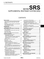
SECTION 8B
SUPPLEMENTAL INFLATABLE RESTRAINTS (SIR)
CAUTION: Disconnect the negative battery cable before removing or installing any electrical unit or when a
tool or equipment could easily come in contact with exposed electrical terminals. Disconnecting this cable
will help prevent personal injury and damage to the vehicle. The ignition must also be in B unless otherwise
noted.
TABLE OF CONTENTS
Description and Operation 8B-3. . . . . . . . . . . . . . . . . .
Airbag Module 8B-3. . . . . . . . . . . . . . . . . . . . . . . . . . . .
Sensing and Diagnostic Module (SDM) 8B-3. . . . . . .
SIR Warning Lamp 8B-3. . . . . . . . . . . . . . . . . . . . . . . .
Clock Spring 8B-4. . . . . . . . . . . . . . . . . . . . . . . . . . . . . .
Wiring Harness/Connectors 8B-4. . . . . . . . . . . . . . . . .
SIR System 8B-4. . . . . . . . . . . . . . . . . . . . . . . . . . . . . .
General Precautions 8B-5. . . . . . . . . . . . . . . . . . . . . . .
Airbag Deployment Condition 8B-5. . . . . . . . . . . . . . .
Airbag Deployment Procedure 8B-6. . . . . . . . . . . . . .
Component Locator 8B-7. . . . . . . . . . . . . . . . . . . . . . . .
SIR Component 8B-7. . . . . . . . . . . . . . . . . . . . . . . . . . .
Diagnostic Information and Procedures 8B-8. . . . .
Bulb Check 8B-8. . . . . . . . . . . . . . . . . . . . . . . . . . . . . . .
Fault Indication 8B-8. . . . . . . . . . . . . . . . . . . . . . . . . . . .
Clearing Fault Codes 8B-8. . . . . . . . . . . . . . . . . . . . . .
Microprocessor – Independent Lamp
Activation 8B-8. . . . . . . . . . . . . . . . . . . . . . . . . . . . . .
System Check 8B-10. . . . . . . . . . . . . . . . . . . . . . . . . . .
Fault Codes 8B-12. . . . . . . . . . . . . . . . . . . . . . . . . . . . .
DTC 01 Driver Firing Circuit,
Resistance Too High 8B-14. . . . . . . . . . . . . . . . . . . .
DTC 02 Driver Firing Circuit,
Resistance Too Low 8B-16. . . . . . . . . . . . . . . . . . . .
DTC 03 Driver Firing Circuit,
Short To Ground 8B-18. . . . . . . . . . . . . . . . . . . . . . .
DTC 04 Driver Firing Circuit,
Short To Battery Voltage 8B-20. . . . . . . . . . . . . . . .
DTC 05 Passenger Firing Circuit,
Resistance Too High 8B-22. . . . . . . . . . . . . . . . . . . .
DTC 06 Passenger Firing Circuit,
Resistance Too Low 8B-24. . . . . . . . . . . . . . . . . . . .
DTC 07 Passenger Firing Circuit,
Short To Ground 8B-26. . . . . . . . . . . . . . . . . . . . . . .
DTC 08 Passenger Firing Circuit,
Short To Battery Voltage 8B-28. . . . . . . . . . . . . . . .
DTC 09 Driver Pretensioner Circuit,
Resistance Too High 8B-30. . . . . . . . . . . . . . . . . . . .
DTC 10 Driver Pretensioner Circuit,
Resistance Too Low 8B-32. . . . . . . . . . . . . . . . . . . .
DTC 11 Driver Pretensioner Circuit,
Short to Ground 8B-34. . . . . . . . . . . . . . . . . . . . . . . .
DTC 12 Driver Pretensioner Circuit,
Short to Battery Voltage 8B-36. . . . . . . . . . . . . . . . .
DTC 13 Passenger Pretensioner Circuit,
Resistance Too High 8B-38. . . . . . . . . . . . . . . . . . . .
DTC 14 Passenger Pretensioner Circuit,
Resistance Too Low 8B-40. . . . . . . . . . . . . . . . . . . .
DTC 15 Passenger Pretensioner Circuit,
Short to Ground 8B-42. . . . . . . . . . . . . . . . . . . . . . . .
DTC 16 Passenger Pretensioner Circuit,
Short to Battery Voltage 8B-44. . . . . . . . . . . . . . . . .
DTC 18 Connection Between Driver Firing
Circuit and Driver Pretensioner Circuit 8B-46. . . . .
DTC 19 Connection Between Driver Firing
Circuit and Passenger Pretensioner Circuit 8B-48
DTC 20 Connection Between Passenger Firing
Circuit and Driver Pretensioner Circuit 8B-50. . . . .
DTC 21 Connection Between Passenger Firing
Circuit and Passenger Pretensioner Circuit 8B-52
DTC 22 Connection Between Driver Pretensioner
Circuit and Passenger Pretensioner Circuit 8B-54
DTC 23 Ignition Input Circuit, Voltage
Too High 8B-56. . . . . . . . . . . . . . . . . . . . . . . . . . . . . .
DTC 24 Ignition Input Circuit, Voltage
Too Low 8B-58. . . . . . . . . . . . . . . . . . . . . . . . . . . . . . .
DTC 25 Warning Lamp Failure 8B-60. . . . . . . . . . . . .
DTC 31 SDM Internal Fault 8B-63. . . . . . . . . . . . . . . .
DTC 32 SDM Crash Recorded 8B-63. . . . . . . . . . . . .
Diagnostic Illustration 1 8B-63. . . . . . . . . . . . . . . . . . .
Diagnostic Illustration 2 8B-64. . . . . . . . . . . . . . . . . . .
Diagnostic Illustration 3 8B-64. . . . . . . . . . . . . . . . . . .
Diagnostic Illustration 4 8B-64. . . . . . . . . . . . . . . . . . .
Diagnostic Illustration 5 8B-64. . . . . . . . . . . . . . . . . . .
Diagnostic Illustration 6 8B-65. . . . . . . . . . . . . . . . . . .
Diagnostic Illustration 7 8B-65. . . . . . . . . . . . . . . . . . .
8B–2 SUPPLEMENTAL INFLATABLE RESTRAINTS (SIR)
DAEWOO M-150 BL2
Diagnostic Illustration 8 8B-65. . . . . . . . . . . . . . . . . . .
Diagnostic Illustration 9 8B-65. . . . . . . . . . . . . . . . . . .
Diagnostic Illustration 10 8B-66. . . . . . . . . . . . . . . . . .
Diagnostic Illustration 11 8B-66. . . . . . . . . . . . . . . . . . .
Diagnostic Illustration 12 8B-66. . . . . . . . . . . . . . . . . .
Diagnostic Illustration 13 8B-66. . . . . . . . . . . . . . . . . .
Diagnostic Illustration 14 8B-67. . . . . . . . . . . . . . . . . .
Diagnostic Illustration 15 8B-67. . . . . . . . . . . . . . . . . .
Diagnostic Illustration 16 8B-67. . . . . . . . . . . . . . . . . .
Diagnostic Illustration 17 8B-67. . . . . . . . . . . . . . . . . .
Diagnostic Illustration 18 8B-68. . . . . . . . . . . . . . . . . .
Diagnostic Illustration 19 8B-68. . . . . . . . . . . . . . . . . .
Diagnostic Illustration 20 8B-68. . . . . . . . . . . . . . . . . .
Diagnostic Illustration 21 8B-68. . . . . . . . . . . . . . . . . .
Repair Instructions 8B-69. . . . . . . . . . . . . . . . . . . . . . . .
On-Vehicle Service 8B-69. . . . . . . . . . . . . . . . . . . . . . . . .
Driver Airbag Module 8B-69. . . . . . . . . . . . . . . . . . . . .
Clock Spring 8B-70. . . . . . . . . . . . . . . . . . . . . . . . . . . . .
Passenger Airbag Module 8B-71. . . . . . . . . . . . . . . . .
Sensing and Diagnostic Module (SDM) 8B-72. . . . . .
Airbag Module Deployment (In Vehicle) 8B-74. . . . . .
Airbag Module Deployment (Outside
of Vehicle) 8B-76. . . . . . . . . . . . . . . . . . . . . . . . . . . . .
Deployed Airbag Module Disposal Procedure 8B-76
Specifications 8B-78. . . . . . . . . . . . . . . . . . . . . . . . . . . .
Fastener Tightening Specifications 8B-78. . . . . . . . . .
Special Tools and Equipment 8B-78. . . . . . . . . . . . . .
Special Tools Table 8B-78. . . . . . . . . . . . . . . . . . . . . . .
Schematic and Routing Diagrams 8B-79. . . . . . . . . .
Supplemental Inflatable Restraints (SIR)
Electrical Schematic 8B-79. . . . . . . . . . . . . . . . . . . .
SUPPLEMENTAL INFLATABLE RESTRAINTS (SIR) 8B– 3
DAEWOO M-150 BL2
DESCRIPTION AND OPERATION
(Left–Hand Drive Shown, Right–Hand Drive Similar)
AIRBAG MODULE
Driver Airbag Module
Caution: Tampering with the driver side airbag
module creates the risk of an injury from an unex-
pected deployment. Therefore, the driver side air-
bag module should never be disassembled.
The driver airbag module is under the center pad on the
steering wheel.
The driver airbag module contains an ignitor charge and
a gas generator to inflate the folded airbag.
D110B006
Passenger Airbag Module
Caution: Tampering with the passenger side airbag
module creates the risk of an injury from an unex-
pected deployment. Therefore, the passenger side
airbag module should never be disassembled.
The passenger airbag module is on the passenger side
of the instrument panel.
The passenger airbag module contains an ignitor charge
and a gas generator to inflate the folded airbag.
SENSING AND DIAGNOSTIC
MODULE (SDM)
The SDM
D Has no user-serviceable parts.
D Is under the front console assembly.
D Continuously monitors the system components.
D Records any faults which are discovered.
D Illuminates a warning lamp that alerts the driver to
any faults.
D Allows the fault codes to be retrieved with a scan tool.
The SDM controls the deployment of the airbag system
through the use of the
D Arming sensor.
D Capacitor.
D Crash sensor, or accelerometer.
D110B007
Arming Sensor
The arming sensor is safety device made up of a dual-
contact, electro-mechanical switch that:
D Acts independently of the electronic components.
D Keeps the firing circuits for the airbags unarmed un-
der normal driving conditions.
D Allows the airbags to deploy under the required
conditions.
Capacitor
The capacitor provides reserve power.
Crash Sensor
The crash sensor, or accelerometer, electronically rep-
resents the acceleration or deceleration of the vehicle
during a frontal impact. In this electronic representation,
the electrical signal is proportional to the acceleration or
deceleration of the vehicle.
SIR WARNING LAMP
The supplemental inflatable restraints (SIR) system in-
cludes a self-diagnostic function.
8B–4 SUPPLEMENTAL INFLATABLE RESTRAINTS (SIR)
DAEWOO M-150 BL2
If there is a failure of the sensing and diagnostic module
or the external circuits, the SIR warning lamp in the in-
strument cluster turns ON.
As a system check, the SIR warning lamp also turns ON
when the ignition is first switched to the ON position.
Correct Functioning
The system is working properly if:
D The SIR warning lamp turns OFF after approximately
four seconds.
Faulty Functioning
The system is not working properly, meaning one of the
SIR components or the wiring connector is faulty, if:
D The SIR warning lamp fails to turn ON when the
ignition is first switched ON.
D The SIR warning lamp remains ON.
D110B009A
CLOCK SPRING
The clock spring:
D Is on the steering column.
D Contains a coil that is the electrical contact between
the steering column wiring harness and the driver
side airbag module.
D Is part of the circuit for the horn.
Notice: Turning the steering wheel more than three and
one-quarter turns may damage the clock spring.
Turning the steering wheel:
D In one direction tightens the coil.
D In the opposite direction loosens the coil.
D More than three and one-quarter turns may damage
the clock spring.
Caution: Disassembling the clock spring can cause
injury and vehicle damage.
The clock spring should never be disassembled.
The clock spring must be replaced if the airbags have
been deployed.
D110B008A
WIRING HARNESS/CONNECTORS
The connector for the sensing and diagnostic module
(SDM) has a built-in shorting bar that will turn ON the
warning lamp if there is a poor connection at the SDM.
As an anti-deployment mechanism, additional shorting
bars are in the
D Connector for the clock spring at the lower steering
column.
D Passenger airbag module connector.
D SDM connector.
When these connectors are separated, the shorting
bars will short circuit any current which is applied, pre-
venting the current from reaching the airbag modules.
SIR SYSTEM
The supplemental inflatable restraints (SIR) system is a
safety device used in conjunction with the seat belts.
The airbag does not replace the function of the seat belt.
The driver and the passengers must always fasten their
seat belts and adjust them for a proper fit.
The SIR is designed to protect the driver and the front
seat passenger in the event of a significant frontal im-
pact to the vehicle. The airbags deploy if the force is ap-
plied from a direction within 30 degrees of the vehicle’s
centerline and above 25 km/h (15 mph) speed.
The SIR consists of a
D Driver airbag module.
D Passenger airbag module.
SUPPLEMENTAL INFLATABLE RESTRAINTS (SIR) 8B– 5
DAEWOO M-150 BL2
D Sensing and diagnostic module.
D Steering column clock spring.
D Wiring harness.
D SIR malfunction warning lamp.
D110B001
GENERAL PRECAUTIONS
The supplemental inflatable restraints (SIR) warning
lamp must illuminate when the ignition is switched ON,
and then turn OFF after approximately 4 seconds.
There is a fault in the airbag system if
D The warning lamp does not turn OFF.
D The warning lamp illuminates while the vehicle is in
operation.
If the warning lamp indicates there is a fault in the airbag
system, assume that the SIR system may not be
functional.
Caution: Failure to follow all service procedures in
the correct sequence can cause the airbag system to
deploy unexpectedly and possibly cause a serious
injury.
Only trained personnel at franchised Daewoo dealers
and authorized Daewoo service dealerships may service
the airbag system.
Never attempt to disassemble, repair, or reuse the
D Airbag modules.
D Clock spring.
D Sensing and diagnostic module.
D Wiring harness.
When making SIR repairs,
D Inspect any SIR part before it is installed.
D Use only new parts.
D Do not install used SIR parts from other vehicles.
D Do not install any part that has been dropped or that
has dents, cracks, or other defects.
AIRBAG DEPLOYMENT CONDITION
Airbag is designed to deploy under 30_ left/right angle
barrier and above 25 km/h (15 mph) speed.
Concrete Barrier Deployment Condition
In case of the 0_ frontal concrete battier, airbag may
deploy above 25 km/h (15 mph) speed.
8B–6 SUPPLEMENTAL INFLATABLE RESTRAINTS (SIR)
DAEWOO M-150 BL2
D110B002
AIRBAG DEPLOYMENT PROCEDURE
1. Non–Deployment condition
a. Initiator
b. Piston
c. Safety disc
d. Compressed Ar gas
D110B003
2. When crashing, firing current flows from the SDM to
the initiator.
3. Initiator is burning and the inside pressure is increas-
ing and the piston hits the safety disc.
D110B004
4. Safety disc is broken and the compressed Ar gas is
spouted out.
D110B005
5. Compressed Ar gas and the burned initiator are car-
bureted. And the airbag is deployed.