daewoo matiz 2000-2013 clutch - hệ thống ly hợp trên xe matiz đời 2000-2013
Bạn đang xem bản rút gọn của tài liệu. Xem và tải ngay bản đầy đủ của tài liệu tại đây (626.66 KB, 14 trang )
DAEWOO M-150 BL2
SECTION 5C
CLUTCH
CAUTION: Disconnect the negative battery cable before removing or installing any electrical unit or when a
tool or equipment could easily come in contact with exposed electrical terminals. Disconnecting this cable
will help prevent personal injury and damage to the vehicle. The ignition must also be in B unless otherwise
noted.
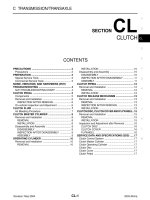
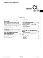
TABLE OF CONTENTS
Description and Operation 5C-2. . . . . . . . . . . . . . . . . .
Driving Members 5C-2. . . . . . . . . . . . . . . . . . . . . . . . . .
Driven Members 5C-2. . . . . . . . . . . . . . . . . . . . . . . . . .
Operating Members 5C-2. . . . . . . . . . . . . . . . . . . . . . .
Component Locator 5C-3. . . . . . . . . . . . . . . . . . . . . . . .
Clutch Components 5C-3. . . . . . . . . . . . . . . . . . . . . . . .
Diagnostic Information and Procedures 5C-4. . . . .
General Diagnosis 5C-4. . . . . . . . . . . . . . . . . . . . . . . . .
Clutch Pedal Operation 5C-5. . . . . . . . . . . . . . . . . . . .
Clutch Cable Adjustment 5C-5. . . . . . . . . . . . . . . . . . .
Repair Instruction 5C-6. . . . . . . . . . . . . . . . . . . . . . . . . .
On-Vehicle Service 5C-6. . . . . . . . . . . . . . . . . . . . . . . . . .
Pressure Plate, Clutch Disc and
Input Shaft Bearing 5C-6. . . . . . . . . . . . . . . . . . . . . . . .
Clutch Release Bearing, Shaft and Bushing 5C-8. . .
Clutch Release Arm 5C-10. . . . . . . . . . . . . . . . . . . . . .
Clutch Cable 5C-11. . . . . . . . . . . . . . . . . . . . . . . . . . . . .
Clutch Pedal 5C-12. . . . . . . . . . . . . . . . . . . . . . . . . . . . .
Specifications 5C-13. . . . . . . . . . . . . . . . . . . . . . . . . . . .
General Specifications 5C-13. . . . . . . . . . . . . . . . . . . .
Fastener Tightening Specifications 5C-13. . . . . . . . . .
Special Tools 5C-14. . . . . . . . . . . . . . . . . . . . . . . . . . . . .
Special Tools Table 5C-14. . . . . . . . . . . . . . . . . . . . . . .
5C –2 CLUTCH
DAEWOO M-150 BL2
DESCRIPTION AND OPERATION
DRIVING MEMBERS
The driving members consist of two flat surfaces ma-
chined to a smooth finish. One of these is the rear face
of the engine flywheel, and the other is the pressure
plate. The pressure plate is fitted into a steel cover,
which is bolted to the flywheel.
DRIVEN MEMBERS
The driven member is the clutch disc with a splined hub
which is free to slide lengthwise along the splines of the
input shaft, but which drives the input shaft through
these same splines.
The driving and driven members are held in contact by
spring pressure. This pressure is exerted by a dia-
phragm spring in the pressure plate assembly.
OPERATING MEMBERS
The clutch release system consists of the clutch pedal,
the clutch release shaft, the clutch cable, the release
arm and the release bearing. When pressure is applied
to the clutch pedal, the clutch release shaft pushes
against the release bearing by rotating. The bearing
then pushes against the diaphragm spring in the pres-
sure plate assembly, thereby releasing the clutch.
CLUTCH 5C–3
DAEWOO M-150 BL2
COMPONENT LOCATOR
CLUTCH COMPONENTS
D13C4011
1 Clutch Disc
2 Pressure Plate
3 Release Bearing
4 Release Shaft
5 Release Shaft Bushing (No.1)
6 Release Shaft Bushing (No.2)
7 Release Shaft Seal
8 Release Arm
9 Clutch Cable Adjusting Nut
10 Clutch Cable
11 Clutch Pedal
5C –4 CLUTCH
DAEWOO M-150 BL2
DIAGNOSTIC INFORMATION AND PROCEDURES
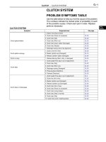
GENERAL DIAGNOSIS
Condition Probable Cause Correction
Slipping Clutch D Improper clutch cable adjustment. D Adjust clutch cable.
D Worn or oily contamination on clutch disc
surface.
D Replace clutch disc.
D Worn or oily contamination on pressure
plate, flywheel surface.
D Replace pressure plate, flywheel.
D Damaged or weakened diaphragm spring. D Replace pressure plate.
D Rusted clutch cable. D Replace clutch cable.
Dragging Clutch D Improper clutch cable adjustment. D Adjust clutch cable.
D Worn or weakened diaphragm spring. D Replace pressure plate.
D Worn or rusted splines of input shaft or
clutch disc.
D Replace input shaft or clutch disc.
D Excessively wobbly clutch disc. D Replace clutch disc.
D Worn clutch disc. D Replace clutch disc.
Fails to Release D Bent or damaged clutch disc. D Replace clutch disc.
D Worn or rusted splines of input shaft or
clutch disc.
D Replace input shaft or clutch disc.
D Improper operation of clutch release shaft. D Replace clutch release shaft.
Pedal Stays on Floor
When Disengaged
D Interfered clutch release bearing. D Lubricate and adjust clutch release
bearing.
D Weakened diaphragm spring. D Replace pressure plate.
Clutch Vibration D Clutch facing with oily contamination. D Replace clutch disc.
D Release bearing slides unsmoothly on input
shaft bearing retainer.
D Lubricate retainer release bearing.
D Wobbly clutch disc or poor facing contact. D Replace clutch disc.
D Loose clutch disc rivets. D Replace clutch disc.
D Weakened clutch disc torsion spring. D Replace clutch disc.
D Distorted pressure plate or flywheel
surface.
D Replace pressure plate or flywheel.
D Weakened engine mounting or loosened
installing bolt or nut.
D Retighten or replace mounting.
Clutch Noise D Worn or broken release bearing. D Replace release bearing.
D Worn input shaft bearing. D Replace input shaft bearing.
D Cracked clutch disc. D Replace clutch disc.
D Pressure plate and diaphragm spring
rattling.
D Replace pressure plate.
D Improper clutch cable adjustment. D Adjust clutch cable.
Grabbing Clutch D Clutch disc facing with oily contamination. D Replace clutch disc.
D Excessively worn on clutch disc facing. D Replace clutch disc.
D Rivet head showing out of facing. D Replace clutch disc.
D Weakened clutch torsion spring. D Replace clutch disc.
CLUTCH 5C–5
DAEWOO M-150 BL2
CLUTCH PEDAL OPERATION
D103C301
Clutch pedal free travel
It is designed that there is no clutch pedal free travel.
Clutch pedal travel (A)
Pedal Travel 100–110 mm (3.9–4.3 in.)
Clearance between pedal and floor just
before clutch connection (B)
After starting the engine, check if the clearance between
pedal and floor is within specified range in condition of
idling, lifting, parking brake and drawing out clutch ped-
al.
Clearance Between Pedal and Floor
just Before Clutch Connection
30–40 mm
(1.2–1.6 in.)
Caution: During inspection, take care on sudden
departure.
CLUTCH CABLE ADJUSTMENT
D103C302
If clutch connection / disconnection is operated un-
smoothly, adjust the clutch cable by adjusting clutch
cable adjust nut.
5C –6 CLUTCH
DAEWOO M-150 BL2
INSTRUCTION REPAIR
ON–VEHICLE SERVICE
D13B5151
D103B516
PRESSURE PLATE, CLUTCH DISC
AND INPUT SHAFT BEARING
Tools Required
09917–58010 Input Shaft Bearing Remover
09924–17810 Flywheel Holder
09925–98210 Input Shaft Bearing Installer
DW110–021 Engine Fixture
DW210–010 Clutch Center Guide
Removal Procedure
1. Remove the transaxle from the vehicle. Refer to Sec-
tion 5B, Manual Transaxle.
2. Support the engine to normal position using the en-
gine fixture DW110–021.
Notice: The abnormal position of the engine may dam-
age to the related parts and interfere with them. You
must support the engine to normal position after remov-
ing the transaxle.
D13C5021
3. Remove the pressure plate and the clutch disc.
D Fix the fly wheel using the fly wheel holder 09924–
17810.
D Remove the pressure plate bolts (1).
D Remove the pressure plate and the clutch disc (2).
CLUTCH 5C–7
DAEWOO M-150 BL2
D13C5031
4. Remove the transaxle input shaft bearing using the
input shaft bearing remover 09917–58010, the fly-
wheel holder 09924–17810 and a spanner.
D13C5041
Inspection Procedure – Pressure Plate
and Clutch Disc
1. Pressure plate inspection .
D Check the weak and damaged diaphragm spring
(1).
D Check the polluted face by the oil, grease (2).
D103C505
2. Clutch disc inspection
D Measure rivet head depth from clutch disc surface
and replace if below limit.
Unit : mm (in.)
Standard Limit
Rivet Head Depth
1.2 (0.047) 0.5 (0.02)
D Replace the clutch disc if clutch disc surface is
contaminated or clutch disc rivets are loosen.
D103C506
3. Clutch disc runout in rotational direction inspection.
D Measure runout in rotational direction and replace
if runout exceeds limit.
Unit : mm (in.)
Disc Runout Limit in Rotational
Direction (Periphery)
0.7 (0.028)
5C –8 CLUTCH
DAEWOO M-150 BL2
D13C5071
Installation Procedure
1. Install in the reverse order of removal.
2. Install the input shaft bearing using the input shaft
bearing installer 09925–98210 and the flywheel hold-
er 09924–17810.
D13C508B
3. Install the pressure plate and the clutch disc.
D Install the clutch disc.
D Install the pressure plate (1).
D Align the pressure plate and the clutch disc onto the
flywheel using the clutch center guide DW210–010
and the flywheel holder 09924–17810.
D Install the pressure plate bolts.
Tighten
Tighten the bolts to 18–28 NSm (13–21 lb-ft).
D103C510
D103C509
CLUTCH RELEASE BEARING, SHAFT
AND BUSHING
Tools Required
09923–46040 Bushing Joint Pipe
09925–48220 Bushing Remover/Installer
09930–30102 Sliding Shaft
09943–88211 Bushing, Bearing Installer
Removal Procedure
1. Remove the transaxle from the vehicle. Refer to Sec-
tion 5B, Manual Transaxle.
2. Remove the release arm. Refer to “Clutch Release
Arm” in this section.
3. Remove the release bearing.
4. Remove the release shaft and bushing.
D Remove the bushing (No.2) and seal using the
bushing remover 09925–48220 and hammer.
D Remove the release shaft (1).
CLUTCH 5C–9
DAEWOO M-150 BL2
D103C511
D Insert the tap (M14X1.5) to the busing (No.1) (2).
D13C512A
D Insert the bushing joint pipe 09923–46040 to the
tab.
D Connect the sliding shaft 09930–30102 to the end
of the bushing joint pipe 09923–46040.
D Remove the bushing (No.1) by pulling.
D103C513
Inspection Procedure – Release Bearing
and Shaft
1. Release bearing inspection
D Check for noisy, worn and damaged release bear-
ing.
D Check for a grabbing rotation of release bearing.
D Replace the release bearing if necessary.
D103C514
2. Release shaft inspection
D Check for a warped shaft (1).
D Check for a worn fork (2).
D Replace the shaft if necessary.
5C –10 CLUTCH
DAEWOO M-150 BL2
D103C515
Installation Procedure
1. Install in the reverse order of removal.
2. Install the release shaft bushing (No.1) using the
bushing joint pipe 09923–46040, bushing, bearing in-
staller 09943–88211 and a hammer.
D103C516
3. Install the release shaft bushing (No.2) and seal using
the bushing remover/installer 09925–48220 and a
hammer.
D103C517
4. Install the release bearing.
D Coat the spline of transaxle input shaft with multi–
purpose grease (1).
D Coat the release bearing bore and the connecting
of release shaft with multi–purpose grease (2).
D Install the release bearing.
D103C518
CLUTCH RELEASE ARM
Removal Procedure
1. Disconnect the clutch cable.
D Remove the adjusting nut (1).
D Disconnect the cable (2).
CLUTCH 5C–11
DAEWOO M-150 BL2
D103C519
2. Remove the clutch release arm.
D Remove the bolt and nut (1).
D Remove the release arm (2).
D13C520A
Installation Procedure
1. Install in the reverse order of removal.
2. Install the clutch release arm.
D Install the clutch release arm matching to punched
mark (1).
Tighten
Tighten the bolt and nut to 10–16 NSm (7.5–12 lb-ft).
3. Adjust the clutch cable. Refer to “Diagnosis” in this
section.
D103B506
CLUTCH CABLE
(Left–Hand Drive Shown, Right–Hand
Drive Similar)
Removal Procedure
1. Disconnect the clutch cable from the transaxle.
D Remove the adjusting nut (1).
D Disconnect the cable from the wire clip (2).
D Pull and remove the cable from the transaxle
mount hole (3).
D13C5211
2. Disconnect the clutch cable from the pedal.
D Pull upward and disconnect the cable from the
pedal hook (1).
5C –12 CLUTCH
DAEWOO M-150 BL2
D103C522
3. Remove the battery. Refer to Section 1E, Engine
Electrical.
4. Remove the clutch cable.
D Remove the nuts (1).
D Remove the cable grommet (2).
D Remove the cable from the pedal (3).
D103C302
Installation Procedure
1. Install the clutch cable.
2 Install the battery.
3. Connect the clutch cable to the pedal.
4. Connect the clutch cable to the transaxle.
5. Adjust the clutch cable. Refer to “Diagnosis” in this
section.
D103C524
CLUTCH PEDAL
(Left–Hand Drive Shown, Right–Hand
Drive Similar)
Removal Procedure
1. Disconnect the clutch cable. Refer to “Clutch Cable”
in this section.
2. Remove the clutch pedal.
D Release the pedal return spring.
D Remove the nut (1).
D Remove the clutch pedal (2).
D Remove the bushing (3).
D Remove the pedal return spring (4).
D103C302
Installation Procedure
1. Install the pedal return spring.
2. Install the bushings.
3. Install the clutch pedal.
4. Install the nut.
5. Fix the pedal return spring.
6. Connect the clutch cable.
7. Adjust the clutch cable. Refer to “Diagnosis” in this
section.
CLUTCH 5C–13
DAEWOO M-150 BL2
SPECIFICATIONS
GENERAL SPECIFICATIONS
Application Description Unit Standard Limit
Type – Single Dry Plate –
Outside Diameter mm (in.) 170 (6.7) –
Inside Diameter mm (in.) 110 (4.3) –
Clutch Disc
Thickness mm (in.) 7.15 (0.281) –
Rivet Head Depth mm (in.) 1.2 (0.047) 0.5 (0.020)
Disc Runout Limit in Rotational Direction mm (in.) – 0.7 (0.028)
Pedal Free Travel mm (in.) 0 (0) –
Clutch Pedal
Pedal Travel mm (in.)
100 – 110
(3.9 – 4.3)
–
Clutch Pedal
Clearance between pedal and floor just
before clutch connection
mm (in.) –
30 – 40
(1.2 – 1.6)
FASTENER TIGHTENING SPECIFICATIONS
Application NSm Lb-Ft Lb-In
Pressure Plate Bolt 18 – 28 13 – 21 –
Clutch Release Arm Bolt and Nut 10 – 16 7.5 – 12 –
5C –14 CLUTCH
DAEWOO M-150 BL2
SPECIAL TOOLS
SPECIAL TOOLS TABLE
D103C101
09917–58010
Input Shaft Bearing
Remover
D103C105
09923–46040
Bushing Joint Pipe
D102B116
09924–17810
Fly Wheel Holder
D103C104
09925–48220
Bushing Remover/
Installer
D103C102
09925–98210
Input Shaft Bearing
Installer
D103C106
09930–30102
Sliding Shaft
D103C107
09943–88211
Bushing, Bearing
Installer
D103B103
DW110–021
Engine Assembly
Support Fixture
D103C103
DW210–010
Clutch Center Guide