daewoo matiz 2000-2013 engine electrical 1-18 - hệ thống điện động cơ trang 1-18 trên xe matiz đời 2000-2013
Bạn đang xem bản rút gọn của tài liệu. Xem và tải ngay bản đầy đủ của tài liệu tại đây (818.66 KB, 18 trang )
DAEWOO M-150 BL2
SECTION 1E
ENGINE ELECTRICAL
CAUTION: Disconnect the negative battery cable before removing or installing any electrical unit or when a
tool or equipment could easily come in contact with exposed electrical terminals. Disconnecting this cable
will help prevent personal injury and damage to the vehicle. The ignition must also be in B unless otherwise
noted.
TABLE OF CONTENTS
Description and Operation 1E-2. . . . . . . . . . . . . . . . . .
Battery 1E-2. . . . . . . . . . . . . . . . . . . . . . . . . . . . . . . . . . .
Ratings 1E-2. . . . . . . . . . . . . . . . . . . . . . . . . . . . . . . . . .
Reserve Capacity 1E-2. . . . . . . . . . . . . . . . . . . . . . . . .
Cold Cranking Amperage 1E-2. . . . . . . . . . . . . . . . . . .
Built-In Hydrometer 1E-2. . . . . . . . . . . . . . . . . . . . . . . .
Charging Procedure 1E-3. . . . . . . . . . . . . . . . . . . . . . .
Charging Time Required 1E-3. . . . . . . . . . . . . . . . . . . .
Charging a Completely Discharged Battery
(Off the Vehicle) 1E-3. . . . . . . . . . . . . . . . . . . . . . . . .
Jump Starting Procedure 1E-3. . . . . . . . . . . . . . . . . . .
Generator 1E-4. . . . . . . . . . . . . . . . . . . . . . . . . . . . . . . .
Charging System 1E-4. . . . . . . . . . . . . . . . . . . . . . . . . .
Starter 1E-4. . . . . . . . . . . . . . . . . . . . . . . . . . . . . . . . . . .
Starting System 1E-4. . . . . . . . . . . . . . . . . . . . . . . . . . .
Distributor 1E-4. . . . . . . . . . . . . . . . . . . . . . . . . . . . . . . .
Ignition Coil 1E-5. . . . . . . . . . . . . . . . . . . . . . . . . . . . . . .
Spark Plug 1E-5. . . . . . . . . . . . . . . . . . . . . . . . . . . . . . .
Component Locator 1E-6. . . . . . . . . . . . . . . . . . . . . . . .
Starting System 1E-6. . . . . . . . . . . . . . . . . . . . . . . . . . .
Charging System (A-type: MANDO) 1E-7. . . . . . . . . .
Charging System (B-type: DAC) 1E-8. . . . . . . . . . . . .
Ignition System 1E-9. . . . . . . . . . . . . . . . . . . . . . . . . . .
Diagnostic Information and Procedure 1E-10. . . . . .
Ignition System 1E-10. . . . . . . . . . . . . . . . . . . . . . . . . .
Battery Load Test 1E-12. . . . . . . . . . . . . . . . . . . . . . . .
Generator Output Test 1E-12. . . . . . . . . . . . . . . . . . . .
Generator System Check 1E-13. . . . . . . . . . . . . . . . . .
Repair Instructions 1E-14. . . . . . . . . . . . . . . . . . . . . . . .
On-Vehicle Service 1E-14. . . . . . . . . . . . . . . . . . . . . . . . .
Starter 1E-14. . . . . . . . . . . . . . . . . . . . . . . . . . . . . . . . . .
Generator 1E-15. . . . . . . . . . . . . . . . . . . . . . . . . . . . . . .
Battery 1E-16. . . . . . . . . . . . . . . . . . . . . . . . . . . . . . . . . .
Distributor 1E-17. . . . . . . . . . . . . . . . . . . . . . . . . . . . . . .
Ignition Coil 1E-18. . . . . . . . . . . . . . . . . . . . . . . . . . . . . .
Unit Repair 1E-19. . . . . . . . . . . . . . . . . . . . . . . . . . . . . . . .
Starter Motor 1E-19. . . . . . . . . . . . . . . . . . . . . . . . . . . .
Generator (A-type: MANDO) 1E-24. . . . . . . . . . . . . . .
Generator (B-type: DAC) 1E-29. . . . . . . . . . . . . . . . . .
Distributor Assembly 1E-34. . . . . . . . . . . . . . . . . . . . . .
Schematic and Routing Diagrams 1E-37. . . . . . . . . .
Starting System 1E-37. . . . . . . . . . . . . . . . . . . . . . . . . .
Charging System 1E-38. . . . . . . . . . . . . . . . . . . . . . . . .
Ignition System Circuit – Tipical 1E-39. . . . . . . . . . . .
Ignition System Circuit – Euro III 1E-40. . . . . . . . . . .
Specifications 1E-41. . . . . . . . . . . . . . . . . . . . . . . . . . . .
Starter Specifications 1E-41. . . . . . . . . . . . . . . . . . . . .
Generator Specifications 1E-41. . . . . . . . . . . . . . . . . .
Ignition System Specifications 1E-41. . . . . . . . . . . . . .
Battery Specifications 1E-41. . . . . . . . . . . . . . . . . . . . .
Fastener Tightening Specifications 1E-42. . . . . . . . . .
1E–2 ENGINE ELECTRICAL
DAEWOO M-150 BL2
DESCRIPTION AND OPERATION
BATTERY
The battery has three major functions in the electrical
system. First, the battery provides a source of energy
for cranking the engine. Second, the battery acts as a
voltage stabilizer for the electrical system. Finally, the
battery can, for a limited time, provide energy when the
electrical demand exceeds the output of the generator.
The sealed battery is standard on all cars. There are no
vent plugs in the cover. The battery is completely
sealed, except for two small vent holes in the sides.
These vent holes allow the small amount of gas pro-
duced in the battery to escape.
The sealed battery has the following advantages over
conventional batteries:
D No water need be added for the life of the battery.
D It is protected against overcharge. If too much volt-
age is applied to the battery, it will not accept as much
current as a conventional battery. In a conventional
battery, the excess voltage will still try to charge the
battery, leading to gassing, which causes liquid loss.
D It is not as liable to self-discharge as a conventional
battery. This is particularly important when a battery
is left standing for long periods of time.
D It has more power available in a lighter and a smaller
case.
RATINGS
A battery has two ratings: (1) A reserve capacity rating
designated at 27_C (81_F), which is the time a fully
charged battery will provide 25 amperes current flow at
or above 10.5 volts; (2) A cold cranking amp rating de-
termined under testing at -18_C (0_ F), which indicates
the cranking load capacity.
RESERVE CAPACITY
The reserve capacity is the maximum length of time it is
possible to travel at night with the minimum electrical
load and no generator output. Expressed in minutes,
Reserve Capacity (or RC rating) is the time required for
a fully charged battery, at a temperature of 27_C (81_F)
and being discharged at a current of 25 amperes, to
reach a terminal voltage of 10.5 volts.
COLD CRANKING AMPERAGE
The cold cranking amperage test is expressed at a bat-
tery temperature of -18_ C (0_F). The current rating is
the minimum amperage, which must be maintained by
the battery for 30 seconds at the specified temperature,
while meeting a minimum voltage requirement of
7.2 volts. This rating is a measure of cold cranking ca-
pacity.
The battery is not designed to last indefinitely. However,
with proper care, the battery will provide many years of
service.
If the battery tests well, but fails to perform satisfactorily
in service for no apparent reason, the following factors
may point to the cause of the trouble:
D Vehicle accessories are left on overnight.
D Slow average driving speeds are used for short peri-
ods.
D The vehicle’s electrical load is more than the genera-
tor output, particularly with the addition of aftermarket
equipment.
D Defects in the charging system, such as electrical
shorts, a slipping generator belt, a faulty generator, or
a faulty voltage regulator.
D Battery abuse, including failure to keep the battery
cable terminals clean and tight, or a loose battery
hold-down.
D Mechanical problems in the electrical system, such
as shorted or pinched wires.
BUILT-IN HYDROMETER
The sealed battery has a built-in, temperature-compen-
sated hydrometer in the top of the battery. This hydrom-
eter is to be used with the following diagnostic
procedure:
1. When observing the hydrometer, make sure that the
battery has a clean top.
2. Under normal operation, two indications can be ob-
served:
D GREEN DOT VISIBLE – Any green appearance is
interpreted as a “green dot,” meaning the battery is
ready for testing.
D DARK GREEN DOT IS NOT VISIBLE – If there is
a cranking complaint, the battery should be tested.
The charging and electrical systems should also
be checked at this time.
3. Occasionally, a third condition may appear:
D CLEAR OR BRIGHT YELLOW – This means the
fluid level is below the bottom of the hydrometer.
This may have been caused by excessive or pro-
longed charging, a broken case, excessive tipping,
or normal battery wear. Finding a battery in this
condition may indicate high charging by a faulty
charging system. Therefore, the charging and the
electrical systems may need to be checked if a
cranking complaint exists. If the cranking com-
plaint is caused by the battery, replace the battery.
ENGINE ELECTRICAL 1E–3
DAEWOO M-150 BL2
CHARGING PROCEDURE
1. Batteries with the green dot showing do not require
charging unless they have just been discharged, such
as in cranking a vehicle.
2. When charging sealed-terminal batteries out of the
vehicle, install the adapter kit. Make sure all the char-
ger connections are clean and tight. For best results,
batteries should be charged while the electrolyte and
the plates are at room temperature. A battery that is
extremely cold may not accept current for several
hours after starting the charger.
3. Charge the battery until the green dot appears. The
battery should be checked every half-hour while
charging. Tipping or shaking the battery may be nec-
essary to make the green dot appear.
4. After charging, the battery should be load tested. Re-
fer to “Starter Motor” in this section.
CHARGING TIME REQUIRED
The time required to charge a battery will vary depend-
ing upon the following factors:
D Size of Battery – A completely discharged large
heavy-duty battery requires more than twice the re-
charging as a completely discharged small passenger
car battery.
D Temperature – A longer time will be needed to
charge any battery at -18_C (0_F) than at 27_C
(81_F). When a fast charger is connected to a cold
battery, the current accepted by the battery will be
very low at first. The battery will accept a higher cur-
rent rate as the battery warms.
D Charger Capacity – A charger which can supply only
5 amperes will require a much longer charging period
than a charger that can supply 30 amperes or more.
D State-of-Charge – A completely discharged battery
requires more than twice as much charge as a one-
half charged battery. Because the electrolyte is nearly
pure water and a poor conductor in a completely dis-
charged battery, the current accepted by the battery
is very low at first. Later, as the charging current
causes the electrolyte acid content to increase, the
charging current will likewise increase.
CHARGING A COMPLETELY
DISCHARGED BATTERY
(OFF THE VEHICLE)
Unless this procedure is properly followed, a perfectly
good battery may be needlessly replaced.
The following procedure should be used to recharge a
completely discharged battery:
1. Measure the voltage at the battery terminals with an
accurate voltmeter. If the reading is below 10 volts,
the charge current will be very low, and it could take
some time before the battery accepts the current in
excess of a few milliamperes. Refer to “Charging
Time Required” in this section, which focuses on the
factors affecting both the charging time required and
the rough estimates in the table below. Such low cur-
rent may not be detectable on ammeters available in
the field.
2. Set the battery charger on the high setting.
Important: Some chargers feature polarity protection
circuitry, which prevents charging unless the charger
leads are correctly connected to the battery terminals. A
completely discharged battery may not have enough
voltage to activate this circuitry, even though the leads
are connected properly, making it appear that the bat-
tery will not accept charging current. Therefore, follow
the specific charger manufacturer’s instruction for by-
passing or overriding the circuitry so that the charger will
turn on and charge a low-voltage battery.
3. Battery chargers vary in the amount of voltage and
current provided. The time required for the battery to
accept a measurable charger current at various volt-
ages may be as follows:
Voltage Hours
16.0 or more Up to 4 hours
14.0–15.9 Up to 8 hours
13.9 or less Up to 16 hours
D If the charge current is not measurable at the end
of the above charging times, the battery should be
replaced.
D If the charge current is measurable during the
charging time, the battery is good, and charging
should be completed in the normal manner.
Important: It is important to remember that a complete-
ly discharged battery must be recharged for a sufficient
number of ampere hours (AH) to restore the battery to a
usable state. As a general rule, using the reserve capac-
ity rating (RC) as the number of ampere hours of charge
usually brings the green dot into view.
D If the charge current is still not measurable after
using the charging time calculated by the above
method, the battery should be replaced.
D If the charge current is measurable during the
charging time, the battery is good, and charging
should be completed in the normal manner.
JUMP STARTING PROCEDURE
1. Position the vehicle with the good (charged) battery
so that the jumper cables will reach from one battery
to the other.
2. Turn off the ignition, all the lights, and all the electrical
loads in both vehicles. Leave the hazard flasher on if
there may be other traffic and any other lights needed
for the work area.
1E–4 ENGINE ELECTRICAL
DAEWOO M-150 BL2
3. In both vehicles, apply the parking brake firmly.
Notice: Make sure the cables are not on or near pulleys,
fans, or other parts that will move when the engine
starts, damaging the parts.
4. Shift a manual transaxle to NEUTRAL.
Caution: Do not use cables that have loose or miss-
ing insulation, or injury could result.
5. Clamp one end of the first jumper cable to the positive
terminal on the battery. Make sure it does not touch
any other metal parts. Clamp the other end of the
same cable to the positive terminal on the other bat-
tery. Never connect the other end to the negative ter-
minal of the discharged battery.
Caution: Do not attach the cable directly to the neg-
ative terminal of the discharged battery. Doing so
could cause sparks and possible battery explosion.
6. Clamp one end of the second cable to the negative
terminal of the booster battery. Make the final con-
nection to a solid engine ground, such as the engine
lift bracket, at least 450 millimeters (18 inches) from
the discharged battery.
7. Start the engine of the vehicle with the good battery.
Run the engine at a moderate speed for several min-
utes. Then start the engine of the vehicle which has
the discharged battery.
8. Remove the jumper cables by reversing the above
sequence exactly. Remove the negative cable from
the vehicle with the discharged battery first. While re-
moving each clamp, take care that it does not touch
any other metal while the other end remains at-
tached
.
GENERATOR
The Delco-Remy CS charging system has several mod-
els available, including the ∅114D (A-type) or CS114D
(B-type). The number denotes the outer diameter in
millimeters of the stator lamination.
CS generators are equipped with internal regulators.
The Y connection (A-type) or Delta (B-type) stator, a
rectifier bridge, and a rotor with slip rings and brushes
are electrically similar to earlier generators. A conven-
tional pulley and fan are used. There is no test hole.
Unlike three-wire generators, the ∅114D (A-type) or
CS114D (B-type) may be used with only two connec-
tions: battery positive and an ‘‘L’’ terminal to the charge
indicator lamp.
As with other charging systems, the charge indicator
lamp lights when the ignition switch is turned to ON, and
goes out when the engine is running. If the charge indi-
cator is on with the engine running, a charging system
defect is indicated.
The regulator voltage setting varies with temperature
and limits the system voltage by controlling the rotor
field current. The regulator switches rotor field current
on and off. By varying the on-off time, correct average
field current for proper system voltage control is ob-
tained. At high speeds, the on-time may be 10 percent
and the off-time 90 percent. At low speeds, with high
electrical loads, on-time may be 90 percent and the off-
time 10 percent.
CHARGING SYSTEM
The Delco-Remy CS charging system has several mod-
els available, including the ∅114D (A-type) or CS114D
(B-type). The number denotes the outer diameter in
millimeters of the stator laminations.
CS generators use a new type of regulator that incorpo-
rates a diode trio. The Y connection (A-type) or Delta (B-
type) stator, a rectifier bridge, and a rotor with slip rings
and brushes are electrically similar to earlier generators.
A conventional pulley and fan are used. There is no test
hole.
STARTER
Wound field starter motors have pole pieces, arranged
around the armature, which are energized by wound
field coils.
Enclosed shift lever cranking motors have the shift lever
mechanism and the solenoid plunger enclosed in the
drive housing, protecting them from exposure to dirt, icy
conditions, and splashes.
In the basic circuit, solenoid windings are energized
when the switch is closed. The resulting plunger and
shift lever movement causes the pinion to engage the
engine flywheel ring gear. The solenoid main contacts
close. Cranking then takes place.
When the engine starts, pinion overrun protects the ar-
mature from excessive speed until the switch is opened,
at which time the return spring causes the pinion to dis-
engage. To prevent excessive overrun, the switch
should be released immediately after the engine starts.
STARTING SYSTEM
The engine electrical system includes the battery, the
ignition, the starter, the generator, and all the related wir-
ing. Diagnostic tables will aid in troubleshooting system
faults. When a fault is traced to a particular component,
refer to that component section of the service manual.
The starting system circuit consists of the battery, the
starter motor, the ignition switch, and all the related elec-
trical wiring. All of these components are connected
electrically.
DISTRIBUTOR
Distributor distributes the high tension voltage induced
from ignition coil, to each spark plug of each cylinder in
ENGINE ELECTRICAL 1E–5
DAEWOO M-150 BL2
the sequence of ignition order. It also adjusts the ignition
timing according to the engine condition.
This vehicle uses the distributor (optical sensor type)
which controls the preminary current of the ignition coil
by the ECM.
The ignition timing change is controlled electronically by
the ECM.
When diagnosing the ignition system, refer to Section
1F, Engine Controls.
IGNITION COIL
Ignition coil is a sort of transformer to generate high volt-
age (15,000–25,000V) which can bring spark at the
spark plugs and has an iron cored closed magnetic type.
The closed magnetic typed ignition coil is used for the
High Energy Ignition (H.E.I) system. Comparing with the
iron cored open magnetic type, the closed type almost
has no loss of magnetic flux, and smaller in size, so it
produces the high voltage of secondary voltage.
SPARK PLUG
It is a part of ignition secondary current, and it burns the
compressed mixture by sparking the high voltage in-
duced from the ignition coil.
1E–6 ENGINE ELECTRICAL
DAEWOO M-150 BL2
COMPONENT LOCATOR
STARTING SYSTEM
D102E401
1 Starter Motor Assembly
2 Starter Solenoid Assembly
3 Starter Housing
4 Shift Lever
5 Armature Set
6 Armature
7 Pinion Gear Assembly
8 Ring Set
9 Field Frame Assembly
10 Brush Holder Assembly
11 Contact End Frame Assembly
12 Starter Through - Bolts
ENGINE ELECTRICAL 1E–7
DAEWOO M-150 BL2
CHARGING SYSTEM (A-TYPE : MANDO)
D102E402
1 Generator Assembly
2 Generator Shackle
3 Generator Drive End Nut
4 Generator Pully
5 Generator Collar (Large)
6 Generator Front Bracket
7 Front Bearing
8 Bearing Spot Plate
9 Generator Collar (Small)
10 Generator Rotor Assembly
11 Rear Bearing
12 Generator Stator Assembly
13 Rectifier Assembly
14 Voltage Regulator / Brush Holder Assembly
15 Generator Rear Bracket
16 Battery Positive Terminal Nut
17 Through Bolt
1E–8 ENGINE ELECTRICAL
DAEWOO M-150 BL2
CHARGING SYSTEM (B-TYPE : DAC)
D102E403
1 Generator Assembly
2 Generator Shackle
3 Generator Drive End Nut
4 Generator Pully
5 Generator Collar
6 Generator Drive End Bracket
7 Generator Stator Assembly
8 Frame Bearing
9 Generator Fan
10 Generator Rotor Assembly
11 Frame Bearing
12 Generator Frame
13 Regulator Assembly
14 Brush Holder Assembly
15 Rectifier Assembly
16 Shield
17 Through - Bolt
18 Generator Cover
19 Battery Positive Terminal Nut
ENGINE ELECTRICAL 1E–9
DAEWOO M-150 BL2
IGNITION SYSTEM
D102E404
1 Ignition Coil
2 Spark Pulg
3 Ignitoin Wire (#0)
4 Ignition Wires (#1, #2, #3)
5 Support Clamp
6 Mounting Clamp
7 Distributor Assembly
8 Coupling
9 Distributor Oil Seal
10 Distributor Housing
11 Distributor Shaft
12 Plate
13 Optical Sensor Unit
14 Plate
15 Bushing
16 Disc Wheel
17 Inner Cover
18 Outer Cover
19 Distributor Rotor
20 Distributor Cap Seal
21 Distributor Cap
1E–10 ENGINE ELECTRICAL
DAEWOO M-150 BL2
DIAGNOSTIC INFORMATION AND PROCEDURE
IGNITION SYSTEM
Condition Probable Cause Correction
No Crank D Low battery voltage. D Charging the battery or Replace
the battery.
D Battery cable is loose, corroded,
or damaged.
D Repair or Replace the battery
cable.
D Faulty starter motor or starter
motor circuit is open.
D Repair or Replace the starter
motor/starter motor circuit.
D Faulty ignition switch or fuse Ef2
is blown.
D Replace the ignition switch or fuse
Ef2.
D Ground short. D Repair the ground short.
Crank OK, But Too Slow D Low battery voltage. D Charging the battery or Replace
the battery.
D Batter.
D Battery cables is loose, corroded,
or damaged.
D Repair or Replace the battery
cable.
D Faulty starter motor. D Repair or Replace the starter
motor.
Starter Motor Does Not Stop D Faulty starter motor. D Repair or Replace the starter
motor.
D Faulty ignition switch. D Replace the ignition switch.
Starter Motor Running, But Not
Cranking
D Broken the clutch pinion gear or
faulty starter motor.
D Replace the starter motor.
D Broken the flywheel ring gear. D Replace the flywheel.
D Connected circuit is open. D Repair the open circuit.
Overcharging Battery D Faulty the IC regulator. D Replace the IC regulator.
Battery Discharge D Loosen the generator drive belt. D Adjust the belt tension or Replace
the belt.
D The circuit is open or a short. D Repair the open or a short circuit.
D Faulty IC regulator. D Replace the IC regulator.
D Battery run down. D Replace the battery.
D Open ground circuit. D Repair the open ground circuit.
Charging Indicator Lamp D Fault IC regulator. D Replace the IC regulator.
Does Not Work When the
Ignition Switch ON
D Charging indicator lamp is blown
or fuse F8 is blown.
D Repair or Replace the charging
indicator lamp/fuse F8.
(Engine Does Not Work)
D Faulty ignition switch. D Replace the ignition switch.
D Generator ground circuit is open
or a short.
D Repair the circuit.
Charging Indicator Lamp D Faulty IC regulator. D Replace the IC regulator.
Does Not Put Out Lights After
Starting the Engine
D Battery cable is corroded or
damaged.
D Repair or Replace the battery
cable.
D Loosen the generator drive belt. D Adjust the belt tension or Replace
the belt.
D Faulty wiring harness. D Repair the wiring harness.
ENGINE ELECTRICAL 1E–11
DAEWOO M-150 BL2
IGNITION SYSTEM (Cont’d)
Condition Probable Cause Correction
Hard to Starting the Engine D Faulty ignition coil. D Replace the ignition coil.
D Faulty distributor (include the
optical sensor).
D Replace the distributor or the
optical sensor.
D Faulty spark plug. D Replace the spark plug or Adjust
the gap.
D Poor ignition timing. D Reset the valve timing.
Engine Idling State is Unstable D Faulty spark plug. D Replace the spark plug or Adjust
the gap.
D Faulty ignition coil. D Replace the ignition coil.
D Poor ignition timing. D Reset the valve timing.
Poor Engine Accelerating D Poor ignition timing. D Reset the valve timing.
1E–12 ENGINE ELECTRICAL
DAEWOO M-150 BL2
BATTERY LOAD TEST
1. Check the battery for obvious damage, such as a
cracked or broken case or cover, which could permit
the loss of electrolyte. If obvious damage is noted, re-
place the battery.
Caution: Do not charge the battery if the hydrometer
is clear or light yellow. Instead, replace the battery. If
the battery feels hot or if violent gassing or spewing
of electrolyte through the vent hole occurs, discontin-
ue charging or reduce the charging rate to avoid inju-
ry.
2. Check the hydrometer. If the green dot is visible, go to
the load test procedure. If the indicator is dark but
green is not visible, charge the battery. For charging a
battery removed from the vehicle, refer to “Charging a
Completely Discharged Battery” in this section.
3. Connect a voltmeter and a battery load tester across
the battery terminals.
4. Apply a 300-ampere load for 15 seconds to remove
any surface charge from the battery.
5. Remove the load.
6. Wait 15 seconds to let the battery recover, and apply
a 270-ampere load.
Important: The battery temperature must be estimated
by touch and by the temperature condition the battery
has been exposed to for the preceding few hours.
7. If the voltage does not drop below the minimum
listed, the battery is good and should be reinstalled. If
the voltage is less than the minimum listed, replace
the battery. Refer to “Battery Specifications” in this
section.
GENERATOR OUTPUT TEST
1. Perform the generator system test. Refer to “Gener-
ator System Check” in this section.
2. Replace the generator if it fails that test. Refer to
“Generator” in the On-Vehicle Service section. If it
passes the test, perform the on-vehicle output
check which follows.
Important: Always check the generator for output be-
fore assuming that a grounded “L” terminal circuit has
damaged the regulator.
3. Attach a digital multimeter (a), an ammeter (b), and
a carbon pile load (c) to the battery (d) and the gen-
erator (e) of the rehicle.
D102E301
Important: Be sure the vehicle battery is fully charged,
and the carbon pile load is turned off.
4. With the ignition switch in the OFF position, check
and record the battery voltage.
5. Remove the harness connector from the generator.
6. Turn the ignition switch to the ON position with the
engine not running. Use a digital multimeter to
check for voltage in the harness connector “L” termi-
nal.
7. The reading should be near the specified battery
voltage of 12 volts. If the voltage is too low, check
the indicator “L” terminal circuits for open and
grounded circuits causing voltage loss. Correct any
open wires, terminal connections, etc., as neces-
sary. Refer to “Charging System” in this section.
8. Attach the generator harness connector.
9. Run the engine at a moderate idle, and measure the
voltage across the battery terminals. The reading
should be above that recorded in Step 4 but less
than 15 volts. If the reading is over 15 volts or below
the previous reading, replace the generator. Refer to
“Generator” in the On-Vehicle Service section.
10. Run the engine at a moderate idle, and measure the
generator amperage output.
11. Turn on the carbon pile, and adjust it to obtain the
maximum amps while maintaining the battery volt-
age above 13 volts.
12. If the reading is within 15 amps of the generator’s
rating noted on the generator, the generator is good.
If not, replace the generator. Refer to “Generator”
in the On-Vehicle Service section.
13. With the generator operating at the maximum out-
put, measure the voltage between the generator
housing and the battery negative terminal. The volt-
age drop should be 0.5 volt or less. If the voltage
drop is more than 0.5 volt, check the ground path
from the generator housing to the negative battery
cable.
14. Check, clean, tighten, and recheck all of the ground
connections.
ENGINE ELECTRICAL 1E–13
DAEWOO M-150 BL2
GENERATOR SYSTEM CHECK
When operating normally, the generator indicator lamp
will come on when the ignition switch is in the ON posi-
tion and go out when the engine starts. If the lamp oper-
ates abnormally or if an undercharged or overcharged
battery condition occurs, the following procedure may
be used to diagnose the charging system. Remember
that an undercharged battery is often caused by acces-
sories being left on overnight or by a defective switch
that allows a lamp, such as a trunk or glove box lamp, to
stay on.
Diagnose the generator with the following procedure:
1. Visually check the belt and wiring.
2. With the ignition switch in the ON position and the en-
gine stopped, the charge indicator lamp should be on.
If not, detach the harness at the generator and
ground the ‘‘L’’ terminal in the harness with a fused,
5-ampere jumper lead.
D If the lamp lights, replace the generator. Refer to
“Generator” in the On-Vehicle Service section.
D If the lamp does not light, locate the open circuit
between the ignition switch and the harness con-
nector. The indicator lamp bulb may be burned out.
3. With the ignition switch in the ON position and the en-
gine running at moderate speed, the charge indicator
lamp should be off. If not, detach the wiring harness
at the generator.
D If the lamp goes off, replace the generator. Refer to
“Generator” in the On-Vehicle Service section.
D If the lamp stays on, check for a short to ground in
the harness between the connector and the indica-
tor lamp.
Important: Always check the generator for output be-
fore assuming that a grounded ‘‘L’’ terminal circuit has
damaged the regulator. Refer to “Generator” in the Unit
Repair section.
1E–14 ENGINE ELECTRICAL
DAEWOO M-150 BL2
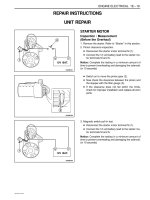
REPAIR INSTRUCTIONS
ON–VEHICLE SERVICE
D12E5011
STARTER
Removal Procedure
1. Disconnect the negative battery cable.
2. Disconnect the electrical connector and clip around
the starter.
D Remove the engine oil temperature sensor to dis-
connect the harness connector (1).
D Remove the starter solenoid nut to disconnect the
electrical cable (2).
D Remove the harness clip bolt to disconnect the
harness clip (3).
D Remove the ground bolt (4).
D102E502
3. Remove the starter assembly.
D Remove the starter mounting bolts (1).
D Remove the starter assembly (2).
D12E5031
Installation procedure
1. Install in the reverse order of removal.
2. Install the starter mounting bolts and starter solenoid
nut.
Tighten
D Tighten the starter mounting bolts to 55–65 NSm
(41–48 lb-ft) (a).
D Tighten the starter solenoid nut to 9–12 NSm
(80–106 lb-in) (b).
D Tighten the harness clip bolt to 9–12 NSm (80–106
lb-in) (c).
D Tighten the ground bolt to 35–41 NSm (26–30 lb-ft)
(d).
ENGINE ELECTRICAL 1E–15
DAEWOO M-150 BL2
D102E504
GENERATOR
Removal Procedure
1. Disconnect the negative battery cable.
2. Disconnect the harness connector.
D Remove the battery harness connector nut to dis-
connect the battery positive connector (1).
D Disconnect the generator harness connector (2).
D102E505
3. Remove the generator drive belt.
D Loosen the generator adjusting bolt (1).
D Remove the lower bracket-to-generator bolt and
nut (2).
D Separate the generator drive belt from the genera-
tor.
D102E506
4. Remove the engine mounting lower bracket.
D Remove the engine mounting lower bracket, at-
taching reaction rod bolt and nut (1).
D Remove the engine mounting lower bracket bolts
(2).
D Remove the engine mounting lower bracket (3).
D102E507
5. Remove the generator.
D Remove the generator adjusting bolt (1).
D Carefully remove the genrator (2).
1E–16 ENGINE ELECTRICAL
DAEWOO M-150 BL2
D12E508A
35–41 NSm
68–83 NSm
Installation Procedure
1. Install in the reverse order of removal except genera-
tor driver velt.
2. Install the engine mounting lower bracket bolts and
nut.
Tighten
D Tighten the engine mounting lower bracket bolts to
35–41 NSm (25–30 lb-ft) (a).
D Tighten the engine mounting lower bracket, attach-
ing reaction rod bolt and nut to 68–83 NSm (50–61
lb-ft) (b).
D12E509A
4–7 NSm
18–28 NSm
3. Install the bolts and nut.
Tighten
D Tighten the generator adjusting bolt to 4–7 NSm
(35–62 lb-in) (a).
D Tighten the generator lower bracket bolt and nut to
18–28 NSm (13–21 lb-ft) (b).
D Inspect the generator drive belt tension.
D12E511A
BATTERY
Removal Procedure
1. Disconnect the negative battery cable and then dis-
connect the positive battery cable.
D Remove the battery cable nut to disconnect the
negative battery cable (1).
D Remove the battery terminal cap (2).
D Remove the battery cable nut to disconnect the
positive battery cable (3).
D102E512
2. Remove the battery.
D Remove the battery rod nut (1).
D Remove the battery rod (2).
D Remove the battery (3).
ENGINE ELECTRICAL 1E–17
DAEWOO M-150 BL2
D12E513A
Installation Procedure
1. Install in the reverse order of removal.
2. Install the battery rod and cable nuts.
Tighten
D Tighten the battery rod nut to 6–8 NSm (53–71 lb-
in) (a).
D Tighten the battery cable nut to 9-12 NSm (80–106
lb-in) (b).
D12E514A
DISTRIBUTOR
Removal Procedure
1. Disconnect the negative battery cable.
2. Remove the air filter, resonator with snorkel assem-
bly. Refer to Section 1B, SOHC Engine Mechanical.
3. Disconnect the ignition wires and electrical connec-
tor.
D Disconnect the optical sensor connector (1).
D Disconnect the ignition wires (2).
D Remove the ignition wire clip (3).
D102E515
4. Remove the distributor.
Important: Mark on the distributor housing and case
before remove distributor (a).
D Remove the distributor bolts (1).
D Carefully remove the distributor assembly (2).
D12E516A
10–16 NSm
Installation Procedure
1. Install in the reverse order of removal.
2. Install the distributor bolts.
Tighten
Tighten the distributor bolts to 10–16 NSm (89–142 lb-
in).
1E–18 ENGINE ELECTRICAL
DAEWOO M-150 BL2
D102E517
IGNITION COIL
Removal Procedure
1. Disconnect the negative battery cable.
2. Disconnect the ignition wires and ignition coil connec-
tor.
D Disconnect the ignition wire (1).
D Disconnect the ignition coil connector by pushing
the connector’s lock(2).
D102E518
3. Remove the ignition coil.
D Remove the screws (1).
D Remove the ignition coil (2).
D12E519A
4–7 NSm
Installation Procedure
1. Install in the reverse order of removal.
2. Install the ignition coil screws.
Tighten
Tighten the ignition coil screws to 4–7 NSm (35–62 lb-
in).